EP2573352B1 - Moteur pour machine de travail portable - Google Patents
Moteur pour machine de travail portable Download PDFInfo
- Publication number
- EP2573352B1 EP2573352B1 EP12006575.0A EP12006575A EP2573352B1 EP 2573352 B1 EP2573352 B1 EP 2573352B1 EP 12006575 A EP12006575 A EP 12006575A EP 2573352 B1 EP2573352 B1 EP 2573352B1
- Authority
- EP
- European Patent Office
- Prior art keywords
- air
- engine
- air suction
- cooling fan
- working machine
- Prior art date
- Legal status (The legal status is an assumption and is not a legal conclusion. Google has not performed a legal analysis and makes no representation as to the accuracy of the status listed.)
- Not-in-force
Links
Images
Classifications
-
- F—MECHANICAL ENGINEERING; LIGHTING; HEATING; WEAPONS; BLASTING
- F02—COMBUSTION ENGINES; HOT-GAS OR COMBUSTION-PRODUCT ENGINE PLANTS
- F02B—INTERNAL-COMBUSTION PISTON ENGINES; COMBUSTION ENGINES IN GENERAL
- F02B63/00—Adaptations of engines for driving pumps, hand-held tools or electric generators; Portable combinations of engines with engine-driven devices
- F02B63/02—Adaptations of engines for driving pumps, hand-held tools or electric generators; Portable combinations of engines with engine-driven devices for hand-held tools
-
- F—MECHANICAL ENGINEERING; LIGHTING; HEATING; WEAPONS; BLASTING
- F01—MACHINES OR ENGINES IN GENERAL; ENGINE PLANTS IN GENERAL; STEAM ENGINES
- F01P—COOLING OF MACHINES OR ENGINES IN GENERAL; COOLING OF INTERNAL-COMBUSTION ENGINES
- F01P5/00—Pumping cooling-air or liquid coolants
- F01P5/02—Pumping cooling-air; Arrangements of cooling-air pumps, e.g. fans or blowers
- F01P5/06—Guiding or ducting air to, or from, ducted fans
Definitions
- the present invention relates to an engine for a working machine, more specifically to an engine that can be used in a portable working machine, such as a brush cutter, a chain saw, and a power blower.
- this sort of engine for a portable working machine includes a casing to cover the engine and a cooling fan coupled to a crankshaft.
- the engine is cooled by flowing cooling air between the engine and the casing.
- the engine for a portable working machine is used in such as a brush cutter, a chain saw and a power blower. Being held up by the user, the engine is tilted in different directions in use. At work, sometimes a portable working machine is placed on the ground while its engine is in the idle state.
- an engine for a portable working machine has been known that has a fuel tank and a bottom cover in its lower part in order to prevent foreign matters such as weeds from getting into between the engine and the casing when the portable working machine is placed on the ground (see Japanese Patent Application Laid-Open No. 2008-75558 ).
- the above-described engine for a portable working machine has a problem that the fuel tank and the bottom cover provided in its lower part may prevent a sufficient amount of cooling air from flowing in the engine. This may cause the performance of the engine to degrade. Therefore, the engine for a portable working machine is designed to ensure that a sufficient amount of cooling air flows therein by forming air flow ports in the bottom cover. However, if the air flow ports of the bottom cover are widened, it is possible to increase an amount of cooling air flowing in the engine for a portable working machine, but foreign matters easily come in the engine.
- JP 8 189359 A discloses a cooling device for a small-sized engine for various kinds of operation machines, wherein a flywheel having a fan and a magnetorotor and directly faced inward of a coil starter is hung from a crank shaft in a journalling manner. External air is suctioned from an intake port by the rotation of the fan to cool a magnet coil and a cylinder while blowing wind therearound.
- a plurality of communication ports which are opened in an axial direction are formed on a center support plate of the flywheel A on the side of an axial center.
- An extended portion of a cylinder cover is connected to a cover installation plate extended from a crank case.
- a lower intake port communicated with a lower space of the crank case is formed on an intermediate portion of the cover installation plate.
- JP 2009 068378 A discloses a cooling device, wherein a cooling fan is arranged in a crank shaft, a fan cover covering the cooling fan is attached to an engine body, and outside air introduced from an air guide port opened in the fan cover is fed on the cylinder head side of the engine body by the cooling fan.
- a sub cooling fan is provided on the engine body side of the cooling fan.
- the crank case is provided with an oil pan section, a cover section opposed to the sub cooling fan, and a recess formed between the oil pan section and the cover section, and moreover, an air guide port communicated with the recess is formed in the cover section.
- the oil pan section and the engine oil reserved in the oil pan section are cooled by the outside air passing the recess and sucked in by the sub cooling fan.
- the engine for a portable working machine includes: a crankshaft to which the working machine is coupled; an air-cooling fan coupled to one end side of the crankshaft; a fan casing enclosing the air-cooling fan; a bottom cover located in a bottom surface side of the engine and connected to the fan casing, an oil pan fixed to a bottom of a crankcase including a crank chamber accommodating the crankshaft, a first air suction port, and a second air suction port.
- the first air suction port and guide parts are formed in a part of the bottom cover near the air-cooling fan, the second air suction port being formed in another part of the bottom cover which is not near the air-cooling fan, the first and second air suction ports sucking in air supplied from the air-cooling fan, and the guide parts extending from the first air suction port to the impeller blades of the air-cooling fan.
- a shielding structure is provided between the first air suction port and the air cooling fan and also between the second air suction port and the air cooling fan, respectively, to shield the air-cooling fan from air coming in from the first and second air suction ports, wherein the oil pan serves as the shielding structure for the second air suction port.
- cooling air is guided to the air-cooling fan side, and, even if foreign matters come in from the air suction ports, the foreign matters are guided to the outer periphery side of the air-cooling fan. Therefore, it is possible to allow the cooling air from the air suction ports to flow in the engine efficiently, and prevent the foreign matters coming in from the air suction ports from adhering to a crankshaft.
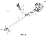
- Fig. 1 to Fig. 3 show an embodiment of the present invention.
- a brush cutter will be explained, as an example of a portable working machine adopting an engine for a portable working machine according to the present invention.
- this brush cutter 1 includes: an operation rod 2 extending in the longitudinal direction; a four-stroke engine 100 connected to the back end side of the operation rod 2; and a disc-shaped cutting blade 4 rotatably attached to the front end side of the operation rod 2 via a gear head 3.
- a drive shaft (not shown) is rotatably provided in the operation rod 2.
- An engine 100 is coupled to the back end side of the drive shaft.
- a gear head 3 is coupled to the front end side of the drive shaft.
- the handle 5 is formed by a tubular member.
- the handle 5 extends from the operation rod 2 to both left and right sides and bends such that both ends turn up.
- Grips 6L and 6R held by the left hand and the right hand of the user are provided in the respective ends of the handle 5.
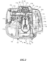
- the engine 100 includes: a carburetor 120 to produce air-fuel mixture to be supplied to a combustion chamber 112a; a fuel tank 130 to accumulate liquid fuel such as gasoline to be supplied to the carburetor 120; an exhaust muffler 140 to discharge combustion gas from the combustion chamber 112a; a bottom cover 160 to cover the bottom surface of the engine 100; and a casing 150 to cover parts other than the bottom surface.
- the engine 100 includes: a cylinder block 112 in which a piston 111 is provided to be able to reciprocate in the vertical direction; a crankcase 113 located below the cylinder block 112 ; a cylinder head 114 above the cylinder block 112 and an oil pan 115 below the crankcase 113.
- the cylinder block 112 has a space in which the piston 111 can reciprocate.
- the combustion chamber 112a is formed between the upper surface of the piston 111 and the cylinder head 114.
- the crankcase 113 includes a crank chamber 113b accommodating a crankshaft 113a.
- the crankshaft 113a is rotatably supported in the crankcase 113, and both front and back ends of the crankshaft 113a project from the crankcase 113 .
- the piston 111 is coupled to the crankshaft 113a via a connecting rod 113c. The reciprocating motion of the piston 111 is converted into the rotational motion of the crankshaft 113a.
- a shaft coupling part 113d is provided in the front end side of the crankshaft 113a.
- the back end side of the drive shaft provided in the operation rod 2 is coupled to the shaft coupling part 113d.
- a fly wheel 113e is provided in the backend side of the crankshaft 113a.
- This fly wheel 113e stabilizes the rotation of the crankshaft 113a and functions as an air-cooling fan that cools the engine 100.
- a plurality of impeller blades 113f are provided on both the front surface side and the back surface side of the fly wheel 113e.
- the plurality of impeller blades 113f on respective surfaces are apart from each other.
- the plurality of impeller blades 113f provided on the fly wheel 113e allow air to flow through in the direction of the diameter of the fly wheel 113e by the rotation of the fly wheel 113e.
- a well-known recoil starter 113g to activate the engine 100 is coupled to the back end side of the crankshaft 113a.
- the fly wheel 113e is surrounded by the crankcase 113, the cylinder block 112, the casing 150 and a recoil starter cover 152.
- a fan casing 110 is formed by these members surrounding the fly wheel
- the cylinder head 114 has an intake port 114a and an exhaust port 114b.
- the intake port 114A introduces the air-fuel mixture produced in the carburetor 120 into the combustion chamber 112a, and the exhaust port 114b introduces the exhaust gas produced in the combustion chamber 112a into the exhaust muffler 140.
- the cylinder head 114 also has an intake valve 114c and an exhaust valve 114d.
- the intake valve 114c opens and closes the intake port 114a with respect to the combustion chamber 112a, and the exhaust port 114d opens and closes the combustion chamber 112a with respect to the exhaust port 114b.
- the intake valve 114c and the exhaust valve 114d open and close by an OHV type valve operating mechanism 114e including a cam shaft, a rocker arm and so forth.
- the oil pan 115 is fixed to the bottom of the crankcase 113.
- An oil tank chamber 115a is formed between the crankcase 113 and the oil pan 115 to accumulate lubricating oil therein.
- the oil tank chamber 115a is connected to the crank chamber 113b via a flexible pipe 115b and a communicating path 115c provided in the crankcase 113, and communicates with the crank chamber 113b according to the reciprocating motion of the piston 111.
- the lubricating oil accumulated in the oil tank chamber 115a lubricates the parts in the crank chamber 113b and the parts constituting the valve operating mechanism 114e, and then returns to the oil tank chamber 115a.
- the carburetor 120 is provided on the left side of the cylinder head 114 and is connected to the intake port 114a. Respective one ends of a suction pipe (not shown) and a return pipe (not shown) are connected to the carburetor 120 while the other ends are connected to the fuel tank 130.
- the fuel tank 130 is formed by a member made of synthetic resin, and provided in a space below the carburetor 120 on the left side of the crankcase 113, as shown in Fig. 2 .
- the exhaust muffler 140 is provided on the right side of the cylinder head 114 and connected to the exhaust port 114b.
- the casing 150 is provided apart from the rear surface of the cylinder block 112.
- An air flow passage 151 is provided between the casing 150 and the rear surface of the cylinder block 112.
- the air flow passage 151 extends in the vertical direction to allow air to flow upward from the bottom end side by the rotation of the fly wheel 113e.
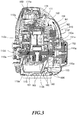
- a partition wall 153 is provided between the oil pan 115 and the fly wheel 113e in the lower part of the air flow passage 151. This partition wall 153 separates between the front side and the back side of the space below the fly wheel 113e along the outline of the fly wheel 113e.
- An extending part 153a extending from the upper end of the partition wall 153 to the oil pan 115 side is provided along the upper end of the partition wall 153.
- An air suction port 151a is formed in a recoil starter cover 152 located in the lower part of the air flow passage 151. Moreover, an exhaust port 151b is provided in the upper right side (the exhaust muffler 140 side) of the air flow passage 151 to discharge the air flowing through the air flow passage 151 to the outside.
- the bottom cover 160 is formed integrally with the fuel tank 13 located in the left side as shown in Fig. 2 .
- Leg parts 161 extending along the longitudinal direction and projecting downward are provided on the bottom surface of the bottom cover 160 at both sides in the width direction of the bottom cover 160.
- a plurality of air suction ports 162 are formed in part of the bottom cover 160, which is between the leg parts 161 and near the fly wheel 113e.
- a plurality of air suction ports 163 are formed in the other part of under cover 160, which is between the leg parts 161 but not near the fly wheel 113e.
- Guide plates 164 are provided on the respective edges of the air suction ports 162 located near the fly wheel 113e and are formed integrally with the bottom cover 160.
- the guide plates 164 guide the air flowing from the air suction ports 162 to the fly wheel 113e side, and also guide the foreign matters such as weeds coming in from the air suction ports 162 to the outer periphery side of the fly wheel 113e.
- Each guide plate 164 extends from the edge of the air suction port 162 to the oil pan 115 side while its end extends obliquely upward to the outer periphery of the fly wheel 113e.
- Shielding structure is provided between the air suction ports 162 and the fly wheel 113e and also between the air suction ports 163 and the fly wheel 113e, respectively, to shield the fly wheel 113e from the air suction ports 162 and 163.
- the fly wheel 113e is shielded from the air suction ports 162 near the flywheel 113e by the partition wall 153, the extending part 153a and the guide plates 164 to prevent the foreign matters coming in from directly contacting the fly wheel 113e. Meanwhile, the fly wheel 113e is shielded by the oil pan 115, from the air suction ports 163 located in the part other than the part near the fly wheel 113e.
- the fly wheel 113e rotates with the crankshaft 113a, and therefore air flows in the air flow passage 151 from the air suction port 151a due to the action of the impeller blades 113f provided on the rear surface of the fly wheel 113e.
- the air having flown into the air flow passage 151 cools the cylinder head 114 and the valve operating mechanism 114e and then is discharged from the exhaust port 151b as indicated by arrow W1 in Fig. 3 .
- the air having flown into the air flow passage 151 cools the oil pan 115, the crankcase 113, the cylinder block 112, the cylinder head 114 and the valve operating mechanism 114e while flowing through the air flow passage 151, and then is discharged from the exhaust port 151b.
- the air flowing from the air suction ports 163 into the air flow passage 151 is guided into the fly wheel 113e side by the guide plates 164.
- weeds may come in from the air suction ports 162 and 163 in the bottom cover 160.
- the weeds coming in from the air suction ports 162 are guided to the outer periphery side of the fly wheel 113e by the guide plates 164.
- the weeds guided by the guide plates 164, to the outer periphery side of the fly wheel 113e are blocked by the partition wall 153 and the extending part 153a, and therefore cannot reach the crankshaft 113a which is the center of the rotating part of the fly wheel 113e.
- the weeds do not adhere to the fly wheel 113e.
- the weeds coming in from the air suction ports 163 are blocked by the oil pan 115, and therefore cannot reach the center of the rotating part of the fly wheel 113e. In addition, even if the engine 100 is being driven, the weeds do not adhere to the fly wheel 113e.
- the air suction ports 162 and the guide plates 164 are provided in one end side of the bottom cover 160.
- the air suction ports 162 suck in the air supplied from the impeller blades 113f of the fly wheel 113e.
- the guide plates 164 extend from the air suction ports 162 to the outside of the impeller blades 113f of the fly wheel 113e.
- the guide plates 164 extend from the air suction ports 162 to the impeller blade 113f of the fly wheel 113e. By this means, it is possible to chop up the weeds coming in from the air suction ports 162 by the impeller blades 113f of the fly wheel 113e to prevent the weeds from adhering to the crankshaft 113a.
- the shielding structure is provided between the air suction ports 162 and the fly wheel 113e and also between the air suction ports 163 and the fly wheel 113e, respectively, to shield the fly wheel 113e from the air suction ports 162 and 163.
- the weeds coming in from the air suction ports 162 and 163 cannot easily reach the center of the rotating part of the fly wheel 113e, and therefore it is possible to effectively prevent the weeds from adhering to the crankshaft 113a.
- the shielding structure is formed by the guide plates 164 and the components constituting the engine 100. Therefore, any dedicated components are not required to form the shielding structure, besides the components constituting the engine 100. Consequently, it is possible to reduce the number of parts. In addition, since the shielding structure is formed by the components constituting the engine 100, design flexibility is higher than in a case in which the shielding structure is provided only by the guide plates 164.
- the shielding structure is formed by the oil pan 115 and the guide plates 164. Therefore, it is possible to flow the air flowing in from the air suction ports 163 along the bottom surface of the oil pan 115, and therefore efficiently cool the lubricating oil in the oil tank chamber 115a.
- a brush cutter 1 has been used as an example of working machines to which the engine 100 is applied, it is by no means limiting.
- a chain saw and a power blower are possible as long as they are portable.
- the four-stroke engine 100 has been used as an example of engines for a working machine, it is by no means limiting.
- the present invention is applicable to a two-stroke engine, and in this case, it is possible to produce the same effect.
- the vertical-mounted engine 100 is used as an example, where the cylinder head 114 is located above the cylinder block 112 and the crankcase 113 is located below the cylinder block 112, it is by no means limiting.
- a traverse-mounted engine is possible where the cylinder head 114 is located in one side of the cylinder block 112 in the horizontal direction, and the crankcase 113 is located in the other side of the cylinder block 112.
- a fan means has a configuration where the fly wheel 113e having both surfaces with the impeller blades 113f is coupled to the crankshaft 113a, it is by no means limiting.
- a dedicated impeller having both surfaces with impeller blades is coupled to the crankshaft 113a as long as it is possible to allow air to flow by the rotation of the crankshaft 113a.
Landscapes
- Engineering & Computer Science (AREA)
- Chemical & Material Sciences (AREA)
- Combustion & Propulsion (AREA)
- Mechanical Engineering (AREA)
- General Engineering & Computer Science (AREA)
- Harvester Elements (AREA)
- Lubrication Details And Ventilation Of Internal Combustion Engines (AREA)
Claims (4)
- Un moteur (100) pour une machine de travail portable (1) comprenant :un vilebrequin (113a) auquel la machine de travail (1) est couplée ;un ventilateur de refroidissement à air (113e) couplé à un côté d'extrémité du vilebrequin (113a) ;un coffrage de ventilateur (110) entourant le ventilateur de refroidissement à air (113e) ;un couvercle inférieur (160) situé sur un côté de surface inférieure du moteur (100) et étant relié au coffrage de ventilateur (110),un bac à huile (115) fixé au fond d'un carter de vilebrequin logeant le vilebrequin (113a),un premier orifice d'aspiration d'air (162), etun deuxième orifice d'aspiration d'air (163),sachant que le premier orifice d'aspiration d'air (162) et des parties de guidage (164) sont formés dans une partie du couvercle inférieur (160) à proximité du ventilateur de refroidissement à air (113e), le deuxième orifice d'aspiration d'air (163) étant formé dans une autre partie du couvercle inférieur (160) qui n'est pas située à proximité du ventilateur de refroidissement à air (113e), les orifices d'aspiration d'air premier et deuxième (162, 163) aspirant de l'air fourni par le ventilateur de refroidissement à air (113e), et les parties de guidage (164) s'étendant depuis le premier orifice d'aspiration d'air (162) vers les pales d'hélice (113f) du ventilateur de refroidissement à air (113e),sachant qu'une structure écran est prévue entre le premier orifice d'aspiration d'air (162) et le ventilateur de refroidissement à air (113e) et également entre le deuxième orifice d'aspiration d'air (163) et le ventilateur de refroidissement à air (113e), respectivement, pour protéger le ventilateur de refroidissement à air (113e) contre l'air provenant des orifices d'aspiration d'air premier et deuxième (162, 163), etsachant que le bac à huile (115) sert de structure écran pour le deuxième orifice d'aspiration d'air (163).
- Le moteur (100) pour une machine de travail portable (1) d'après la revendication 1, sachant que les pièces de guidage (164) s'étendent depuis le premier orifice d'aspiration d'air (162) aux pales d'hélice (113f) du ventilateur de refroidissement à air (113e).
- Le moteur (100) pour une machine de travail portable (1) d'après l'une des revendications 1 et 2, sachant que la structure écran est formée par les parties de guidage (164), et des composants incluant un bloc-cylindres (112) et un carter de vilebrequin (113) qui constituent le moteur (100).
- Le moteur (100) pour une machine de travail portable (1) d'après l'une des revendications de 1 à 3, sachant que :le moteur (100) pour une machine de travail portable (1) comprend un moteur à quatre temps configuré pour lubrifier des pièces d'entraînement en faisant circuler de l'huile lubrifiante et comporte le bac à huile (115) pour accumuler l'huile lubrifiante ; et quela structure écran est formée par le bac à huile (115) et les pièces de guidage (164).
Applications Claiming Priority (1)
| Application Number | Priority Date | Filing Date | Title |
|---|---|---|---|
| JP2011205974A JP5825951B2 (ja) | 2011-09-21 | 2011-09-21 | 携帯型作業機用エンジン |
Publications (2)
| Publication Number | Publication Date |
|---|---|
| EP2573352A1 EP2573352A1 (fr) | 2013-03-27 |
| EP2573352B1 true EP2573352B1 (fr) | 2019-08-28 |
Family
ID=47008220
Family Applications (1)
| Application Number | Title | Priority Date | Filing Date |
|---|---|---|---|
| EP12006575.0A Not-in-force EP2573352B1 (fr) | 2011-09-21 | 2012-09-19 | Moteur pour machine de travail portable |
Country Status (5)
| Country | Link |
|---|---|
| US (1) | US8763567B2 (fr) |
| EP (1) | EP2573352B1 (fr) |
| JP (1) | JP5825951B2 (fr) |
| CN (1) | CN103016128B (fr) |
| RU (1) | RU2012140343A (fr) |
Families Citing this family (3)
| Publication number | Priority date | Publication date | Assignee | Title |
|---|---|---|---|---|
| MX2018001383A (es) * | 2017-02-01 | 2018-11-29 | Tvs Motor Co Ltd | Un sistema de enfriamiento para un motor de combustion interna. |
| WO2019187083A1 (fr) | 2018-03-30 | 2019-10-03 | 本田技研工業株式会社 | Moteur polyvalent |
| CN119308756B (zh) * | 2024-12-17 | 2025-05-06 | 浙江欧欧动力机械有限公司 | 一种农林机械用的小型发动机 |
Family Cites Families (15)
| Publication number | Priority date | Publication date | Assignee | Title |
|---|---|---|---|---|
| US4711750A (en) * | 1977-12-19 | 1987-12-08 | Norton Company | Abrasive casting process |
| US4536132A (en) * | 1981-02-25 | 1985-08-20 | London Fog, Inc. | Gas compressor |
| US5035586A (en) * | 1989-04-19 | 1991-07-30 | White Consolidated Industries, Inc. | Portable hand-held blower/vacuum unit with resilient engine mounting system |
| US5269665A (en) * | 1989-04-19 | 1993-12-14 | White Consolidated Industries, Inc. | Portable hand-held blower/vacuum unit with resilient engine mounting system |
| JPH0479929U (fr) * | 1990-11-27 | 1992-07-13 | ||
| JP2564419Y2 (ja) * | 1992-05-13 | 1998-03-09 | 三菱重工業株式会社 | エンジンの冷却空気吸入孔 |
| JPH08189359A (ja) | 1995-01-10 | 1996-07-23 | Fuji Robin Ind Ltd | 小形エンジンの空冷装置 |
| US6305909B1 (en) * | 2000-02-25 | 2001-10-23 | Mtd Southwest Inc. | Engine arrangement for blowers and blower/vacuums |
| US7341027B2 (en) * | 2006-01-20 | 2008-03-11 | Makita Numazu Corporation | Portable 4-cycle engine and portable machine equipped with the 4-cycle engine |
| JP5072298B2 (ja) | 2006-09-21 | 2012-11-14 | 株式会社マキタ | 小型可搬式作業機械用の空冷エンジン |
| US7922443B2 (en) * | 2007-02-02 | 2011-04-12 | Kawasaki Jukogyo Kabushiki Kaisha | Portable air blower |
| JP4864842B2 (ja) * | 2007-09-11 | 2012-02-01 | 富士重工業株式会社 | 空冷式エンジンの冷却装置 |
| US7950355B2 (en) * | 2008-05-30 | 2011-05-31 | Kawasaki Jukogyo Kabushiki Kaisha | Air-cooled engine having improved dust preventive structure |
| JP5484835B2 (ja) * | 2009-09-02 | 2014-05-07 | 本田技研工業株式会社 | 鞍乗り型車両の吸気構造 |
| CN101943076B (zh) * | 2010-10-19 | 2011-12-28 | 无锡开普动力有限公司 | 发动机的气缸盖冷却结构 |
-
2011
- 2011-09-21 JP JP2011205974A patent/JP5825951B2/ja not_active Expired - Fee Related
-
2012
- 2012-09-11 US US13/609,450 patent/US8763567B2/en not_active Expired - Fee Related
- 2012-09-19 EP EP12006575.0A patent/EP2573352B1/fr not_active Not-in-force
- 2012-09-20 RU RU2012140343/06A patent/RU2012140343A/ru not_active Application Discontinuation
- 2012-09-21 CN CN201210356572.4A patent/CN103016128B/zh not_active Expired - Fee Related
Non-Patent Citations (1)
| Title |
|---|
| None * |
Also Published As
| Publication number | Publication date |
|---|---|
| CN103016128B (zh) | 2015-02-18 |
| US20130068179A1 (en) | 2013-03-21 |
| EP2573352A1 (fr) | 2013-03-27 |
| JP2013068118A (ja) | 2013-04-18 |
| CN103016128A (zh) | 2013-04-03 |
| JP5825951B2 (ja) | 2015-12-02 |
| US8763567B2 (en) | 2014-07-01 |
| RU2012140343A (ru) | 2014-03-27 |
Similar Documents
| Publication | Publication Date | Title |
|---|---|---|
| CN102428255B (zh) | 四冲程发动机、含该机器的灌木清除机和发动机驱动工具 | |
| US8915219B2 (en) | Working machine engine and working machine using the same | |
| JP6200074B2 (ja) | エンジン | |
| JP2011177864A (ja) | エンジンカッター | |
| EP2573352B1 (fr) | Moteur pour machine de travail portable | |
| CN1201067C (zh) | Ohc发动机的润滑结构 | |
| US8646418B2 (en) | Four-stroke engine and working machine using the same | |
| US8387595B2 (en) | Lubricating device for four-stroke engine | |
| CN1370913A (zh) | 四冲程ohc发动机的润滑结构 | |
| JP3819591B2 (ja) | 空冷エンジン | |
| JP5387305B2 (ja) | ダイヤフラム式キャブレター用ガスケットおよびそれを備える4サイクルエンジンならびにその4サイクルエンジンを備えるエンジン工具 | |
| JP5413108B2 (ja) | 4サイクルエンジンおよびそれを備えた刈払機ならびにエンジン工具 | |
| JP5413107B2 (ja) | 4サイクルエンジンおよびそれを備える刈払機ならびにエンジン工具 | |
| JP5515576B2 (ja) | エンジンおよびそれを備えたエンジン工具 | |
| JP2013068119A (ja) | 携帯型作業機用エンジン | |
| JP5521471B2 (ja) | 頭上弁式エンジンおよびそれを備えるエンジン工具 | |
| CN106662038A (zh) | 二冲程发动机、发动机式作业机 | |
| JP5387304B2 (ja) | 頭上弁式エンジンおよびそれを備えるエンジン工具 | |
| WO2007132915A1 (fr) | Machine-outil portable | |
| EP2079919A1 (fr) | Carter et moteur à combustion interne |
Legal Events
| Date | Code | Title | Description |
|---|---|---|---|
| PUAI | Public reference made under article 153(3) epc to a published international application that has entered the european phase |
Free format text: ORIGINAL CODE: 0009012 |
|
| AK | Designated contracting states |
Kind code of ref document: A1 Designated state(s): AL AT BE BG CH CY CZ DE DK EE ES FI FR GB GR HR HU IE IS IT LI LT LU LV MC MK MT NL NO PL PT RO RS SE SI SK SM TR |
|
| AX | Request for extension of the european patent |
Extension state: BA ME |
|
| 17P | Request for examination filed |
Effective date: 20130912 |
|
| RBV | Designated contracting states (corrected) |
Designated state(s): AL AT BE BG CH CY CZ DE DK EE ES FI FR GB GR HR HU IE IS IT LI LT LU LV MC MK MT NL NO PL PT RO RS SE SI SK SM TR |
|
| 17Q | First examination report despatched |
Effective date: 20151002 |
|
| STAA | Information on the status of an ep patent application or granted ep patent |
Free format text: STATUS: EXAMINATION IS IN PROGRESS |
|
| GRAP | Despatch of communication of intention to grant a patent |
Free format text: ORIGINAL CODE: EPIDOSNIGR1 |
|
| STAA | Information on the status of an ep patent application or granted ep patent |
Free format text: STATUS: GRANT OF PATENT IS INTENDED |
|
| INTG | Intention to grant announced |
Effective date: 20190205 |
|
| GRAS | Grant fee paid |
Free format text: ORIGINAL CODE: EPIDOSNIGR3 |
|
| RIN1 | Information on inventor provided before grant (corrected) |
Inventor name: NAKAMURA, YUKI |
|
| GRAA | (expected) grant |
Free format text: ORIGINAL CODE: 0009210 |
|
| STAA | Information on the status of an ep patent application or granted ep patent |
Free format text: STATUS: THE PATENT HAS BEEN GRANTED |
|
| AK | Designated contracting states |
Kind code of ref document: B1 Designated state(s): AL AT BE BG CH CY CZ DE DK EE ES FI FR GB GR HR HU IE IS IT LI LT LU LV MC MK MT NL NO PL PT RO RS SE SI SK SM TR |
|
| REG | Reference to a national code |
Ref country code: GB Ref legal event code: FG4D |
|
| REG | Reference to a national code |
Ref country code: CH Ref legal event code: EP |
|
| REG | Reference to a national code |
Ref country code: AT Ref legal event code: REF Ref document number: 1172676 Country of ref document: AT Kind code of ref document: T Effective date: 20190915 |
|
| REG | Reference to a national code |
Ref country code: IE Ref legal event code: FG4D |
|
| REG | Reference to a national code |
Ref country code: DE Ref legal event code: R096 Ref document number: 602012063297 Country of ref document: DE |
|
| REG | Reference to a national code |
Ref country code: NL Ref legal event code: MP Effective date: 20190828 |
|
| REG | Reference to a national code |
Ref country code: LT Ref legal event code: MG4D |
|
| PG25 | Lapsed in a contracting state [announced via postgrant information from national office to epo] |
Ref country code: FI Free format text: LAPSE BECAUSE OF FAILURE TO SUBMIT A TRANSLATION OF THE DESCRIPTION OR TO PAY THE FEE WITHIN THE PRESCRIBED TIME-LIMIT Effective date: 20190828 Ref country code: HR Free format text: LAPSE BECAUSE OF FAILURE TO SUBMIT A TRANSLATION OF THE DESCRIPTION OR TO PAY THE FEE WITHIN THE PRESCRIBED TIME-LIMIT Effective date: 20190828 Ref country code: PT Free format text: LAPSE BECAUSE OF FAILURE TO SUBMIT A TRANSLATION OF THE DESCRIPTION OR TO PAY THE FEE WITHIN THE PRESCRIBED TIME-LIMIT Effective date: 20191230 Ref country code: NL Free format text: LAPSE BECAUSE OF FAILURE TO SUBMIT A TRANSLATION OF THE DESCRIPTION OR TO PAY THE FEE WITHIN THE PRESCRIBED TIME-LIMIT Effective date: 20190828 Ref country code: LT Free format text: LAPSE BECAUSE OF FAILURE TO SUBMIT A TRANSLATION OF THE DESCRIPTION OR TO PAY THE FEE WITHIN THE PRESCRIBED TIME-LIMIT Effective date: 20190828 Ref country code: BG Free format text: LAPSE BECAUSE OF FAILURE TO SUBMIT A TRANSLATION OF THE DESCRIPTION OR TO PAY THE FEE WITHIN THE PRESCRIBED TIME-LIMIT Effective date: 20191128 Ref country code: NO Free format text: LAPSE BECAUSE OF FAILURE TO SUBMIT A TRANSLATION OF THE DESCRIPTION OR TO PAY THE FEE WITHIN THE PRESCRIBED TIME-LIMIT Effective date: 20191128 Ref country code: SE Free format text: LAPSE BECAUSE OF FAILURE TO SUBMIT A TRANSLATION OF THE DESCRIPTION OR TO PAY THE FEE WITHIN THE PRESCRIBED TIME-LIMIT Effective date: 20190828 |
|
| PGFP | Annual fee paid to national office [announced via postgrant information from national office to epo] |
Ref country code: DE Payment date: 20190927 Year of fee payment: 8 |
|
| PG25 | Lapsed in a contracting state [announced via postgrant information from national office to epo] |
Ref country code: RS Free format text: LAPSE BECAUSE OF FAILURE TO SUBMIT A TRANSLATION OF THE DESCRIPTION OR TO PAY THE FEE WITHIN THE PRESCRIBED TIME-LIMIT Effective date: 20190828 Ref country code: GR Free format text: LAPSE BECAUSE OF FAILURE TO SUBMIT A TRANSLATION OF THE DESCRIPTION OR TO PAY THE FEE WITHIN THE PRESCRIBED TIME-LIMIT Effective date: 20191129 Ref country code: IS Free format text: LAPSE BECAUSE OF FAILURE TO SUBMIT A TRANSLATION OF THE DESCRIPTION OR TO PAY THE FEE WITHIN THE PRESCRIBED TIME-LIMIT Effective date: 20191228 Ref country code: AL Free format text: LAPSE BECAUSE OF FAILURE TO SUBMIT A TRANSLATION OF THE DESCRIPTION OR TO PAY THE FEE WITHIN THE PRESCRIBED TIME-LIMIT Effective date: 20190828 Ref country code: ES Free format text: LAPSE BECAUSE OF FAILURE TO SUBMIT A TRANSLATION OF THE DESCRIPTION OR TO PAY THE FEE WITHIN THE PRESCRIBED TIME-LIMIT Effective date: 20190828 Ref country code: LV Free format text: LAPSE BECAUSE OF FAILURE TO SUBMIT A TRANSLATION OF THE DESCRIPTION OR TO PAY THE FEE WITHIN THE PRESCRIBED TIME-LIMIT Effective date: 20190828 |
|
| REG | Reference to a national code |
Ref country code: AT Ref legal event code: MK05 Ref document number: 1172676 Country of ref document: AT Kind code of ref document: T Effective date: 20190828 |
|
| PG25 | Lapsed in a contracting state [announced via postgrant information from national office to epo] |
Ref country code: TR Free format text: LAPSE BECAUSE OF FAILURE TO SUBMIT A TRANSLATION OF THE DESCRIPTION OR TO PAY THE FEE WITHIN THE PRESCRIBED TIME-LIMIT Effective date: 20190828 |
|
| PG25 | Lapsed in a contracting state [announced via postgrant information from national office to epo] |
Ref country code: PL Free format text: LAPSE BECAUSE OF FAILURE TO SUBMIT A TRANSLATION OF THE DESCRIPTION OR TO PAY THE FEE WITHIN THE PRESCRIBED TIME-LIMIT Effective date: 20190828 Ref country code: EE Free format text: LAPSE BECAUSE OF FAILURE TO SUBMIT A TRANSLATION OF THE DESCRIPTION OR TO PAY THE FEE WITHIN THE PRESCRIBED TIME-LIMIT Effective date: 20190828 Ref country code: AT Free format text: LAPSE BECAUSE OF FAILURE TO SUBMIT A TRANSLATION OF THE DESCRIPTION OR TO PAY THE FEE WITHIN THE PRESCRIBED TIME-LIMIT Effective date: 20190828 Ref country code: IT Free format text: LAPSE BECAUSE OF FAILURE TO SUBMIT A TRANSLATION OF THE DESCRIPTION OR TO PAY THE FEE WITHIN THE PRESCRIBED TIME-LIMIT Effective date: 20190828 Ref country code: DK Free format text: LAPSE BECAUSE OF FAILURE TO SUBMIT A TRANSLATION OF THE DESCRIPTION OR TO PAY THE FEE WITHIN THE PRESCRIBED TIME-LIMIT Effective date: 20190828 Ref country code: RO Free format text: LAPSE BECAUSE OF FAILURE TO SUBMIT A TRANSLATION OF THE DESCRIPTION OR TO PAY THE FEE WITHIN THE PRESCRIBED TIME-LIMIT Effective date: 20190828 |
|
| PG25 | Lapsed in a contracting state [announced via postgrant information from national office to epo] |
Ref country code: SK Free format text: LAPSE BECAUSE OF FAILURE TO SUBMIT A TRANSLATION OF THE DESCRIPTION OR TO PAY THE FEE WITHIN THE PRESCRIBED TIME-LIMIT Effective date: 20190828 Ref country code: MC Free format text: LAPSE BECAUSE OF FAILURE TO SUBMIT A TRANSLATION OF THE DESCRIPTION OR TO PAY THE FEE WITHIN THE PRESCRIBED TIME-LIMIT Effective date: 20190828 Ref country code: CZ Free format text: LAPSE BECAUSE OF FAILURE TO SUBMIT A TRANSLATION OF THE DESCRIPTION OR TO PAY THE FEE WITHIN THE PRESCRIBED TIME-LIMIT Effective date: 20190828 Ref country code: IS Free format text: LAPSE BECAUSE OF FAILURE TO SUBMIT A TRANSLATION OF THE DESCRIPTION OR TO PAY THE FEE WITHIN THE PRESCRIBED TIME-LIMIT Effective date: 20200224 Ref country code: SM Free format text: LAPSE BECAUSE OF FAILURE TO SUBMIT A TRANSLATION OF THE DESCRIPTION OR TO PAY THE FEE WITHIN THE PRESCRIBED TIME-LIMIT Effective date: 20190828 |
|
| REG | Reference to a national code |
Ref country code: CH Ref legal event code: PL |
|
| REG | Reference to a national code |
Ref country code: DE Ref legal event code: R097 Ref document number: 602012063297 Country of ref document: DE |
|
| PLBE | No opposition filed within time limit |
Free format text: ORIGINAL CODE: 0009261 |
|
| STAA | Information on the status of an ep patent application or granted ep patent |
Free format text: STATUS: NO OPPOSITION FILED WITHIN TIME LIMIT |
|
| PG2D | Information on lapse in contracting state deleted |
Ref country code: IS |
|
| PG25 | Lapsed in a contracting state [announced via postgrant information from national office to epo] |
Ref country code: LU Free format text: LAPSE BECAUSE OF NON-PAYMENT OF DUE FEES Effective date: 20190919 Ref country code: IE Free format text: LAPSE BECAUSE OF NON-PAYMENT OF DUE FEES Effective date: 20190919 Ref country code: CH Free format text: LAPSE BECAUSE OF NON-PAYMENT OF DUE FEES Effective date: 20190930 Ref country code: LI Free format text: LAPSE BECAUSE OF NON-PAYMENT OF DUE FEES Effective date: 20190930 |
|
| REG | Reference to a national code |
Ref country code: BE Ref legal event code: MM Effective date: 20190930 |
|
| 26N | No opposition filed |
Effective date: 20200603 |
|
| PG25 | Lapsed in a contracting state [announced via postgrant information from national office to epo] |
Ref country code: SI Free format text: LAPSE BECAUSE OF FAILURE TO SUBMIT A TRANSLATION OF THE DESCRIPTION OR TO PAY THE FEE WITHIN THE PRESCRIBED TIME-LIMIT Effective date: 20190828 Ref country code: BE Free format text: LAPSE BECAUSE OF NON-PAYMENT OF DUE FEES Effective date: 20190930 |
|
| GBPC | Gb: european patent ceased through non-payment of renewal fee |
Effective date: 20191128 |
|
| PG25 | Lapsed in a contracting state [announced via postgrant information from national office to epo] |
Ref country code: GB Free format text: LAPSE BECAUSE OF NON-PAYMENT OF DUE FEES Effective date: 20191128 Ref country code: FR Free format text: LAPSE BECAUSE OF NON-PAYMENT OF DUE FEES Effective date: 20191028 |
|
| REG | Reference to a national code |
Ref country code: DE Ref legal event code: R119 Ref document number: 602012063297 Country of ref document: DE |
|
| PG25 | Lapsed in a contracting state [announced via postgrant information from national office to epo] |
Ref country code: CY Free format text: LAPSE BECAUSE OF FAILURE TO SUBMIT A TRANSLATION OF THE DESCRIPTION OR TO PAY THE FEE WITHIN THE PRESCRIBED TIME-LIMIT Effective date: 20190828 |
|
| PG25 | Lapsed in a contracting state [announced via postgrant information from national office to epo] |
Ref country code: DE Free format text: LAPSE BECAUSE OF NON-PAYMENT OF DUE FEES Effective date: 20210401 Ref country code: HU Free format text: LAPSE BECAUSE OF FAILURE TO SUBMIT A TRANSLATION OF THE DESCRIPTION OR TO PAY THE FEE WITHIN THE PRESCRIBED TIME-LIMIT; INVALID AB INITIO Effective date: 20120919 Ref country code: MT Free format text: LAPSE BECAUSE OF FAILURE TO SUBMIT A TRANSLATION OF THE DESCRIPTION OR TO PAY THE FEE WITHIN THE PRESCRIBED TIME-LIMIT Effective date: 20190828 |
|
| PG25 | Lapsed in a contracting state [announced via postgrant information from national office to epo] |
Ref country code: MK Free format text: LAPSE BECAUSE OF FAILURE TO SUBMIT A TRANSLATION OF THE DESCRIPTION OR TO PAY THE FEE WITHIN THE PRESCRIBED TIME-LIMIT Effective date: 20190828 |