EP2573367B1 - Sensorsystem - Google Patents
Sensorsystem Download PDFInfo
- Publication number
- EP2573367B1 EP2573367B1 EP12185414.5A EP12185414A EP2573367B1 EP 2573367 B1 EP2573367 B1 EP 2573367B1 EP 12185414 A EP12185414 A EP 12185414A EP 2573367 B1 EP2573367 B1 EP 2573367B1
- Authority
- EP
- European Patent Office
- Prior art keywords
- data
- sensors
- temperature
- sensor
- alarm
- Prior art date
- Legal status (The legal status is an assumption and is not a legal conclusion. Google has not performed a legal analysis and makes no representation as to the accuracy of the status listed.)
- Active
Links
Images


Classifications
-
- F—MECHANICAL ENGINEERING; LIGHTING; HEATING; WEAPONS; BLASTING
- F02—COMBUSTION ENGINES; HOT-GAS OR COMBUSTION-PRODUCT ENGINE PLANTS
- F02C—GAS-TURBINE PLANTS; AIR INTAKES FOR JET-PROPULSION PLANTS; CONTROLLING FUEL SUPPLY IN AIR-BREATHING JET-PROPULSION PLANTS
- F02C9/00—Controlling gas-turbine plants; Controlling fuel supply in air- breathing jet-propulsion plants
- F02C9/26—Control of fuel supply
- F02C9/28—Regulating systems responsive to plant or ambient parameters, e.g. temperature, pressure, rotor speed
-
- G—PHYSICS
- G01—MEASURING; TESTING
- G01J—MEASUREMENT OF INTENSITY, VELOCITY, SPECTRAL CONTENT, POLARISATION, PHASE OR PULSE CHARACTERISTICS OF INFRARED, VISIBLE OR ULTRAVIOLET LIGHT; COLORIMETRY; RADIATION PYROMETRY
- G01J5/00—Radiation pyrometry, e.g. infrared or optical thermometry
- G01J5/0014—Radiation pyrometry, e.g. infrared or optical thermometry for sensing the radiation from gases, flames
-
- G—PHYSICS
- G01—MEASURING; TESTING
- G01J—MEASUREMENT OF INTENSITY, VELOCITY, SPECTRAL CONTENT, POLARISATION, PHASE OR PULSE CHARACTERISTICS OF INFRARED, VISIBLE OR ULTRAVIOLET LIGHT; COLORIMETRY; RADIATION PYROMETRY
- G01J5/00—Radiation pyrometry, e.g. infrared or optical thermometry
- G01J5/0066—Radiation pyrometry, e.g. infrared or optical thermometry for hot spots detection
-
- G—PHYSICS
- G01—MEASURING; TESTING
- G01J—MEASUREMENT OF INTENSITY, VELOCITY, SPECTRAL CONTENT, POLARISATION, PHASE OR PULSE CHARACTERISTICS OF INFRARED, VISIBLE OR ULTRAVIOLET LIGHT; COLORIMETRY; RADIATION PYROMETRY
- G01J5/00—Radiation pyrometry, e.g. infrared or optical thermometry
- G01J5/02—Constructional details
- G01J5/025—Interfacing a pyrometer to an external device or network; User interface
-
- F—MECHANICAL ENGINEERING; LIGHTING; HEATING; WEAPONS; BLASTING
- F05—INDEXING SCHEMES RELATING TO ENGINES OR PUMPS IN VARIOUS SUBCLASSES OF CLASSES F01-F04
- F05D—INDEXING SCHEME FOR ASPECTS RELATING TO NON-POSITIVE-DISPLACEMENT MACHINES OR ENGINES, GAS-TURBINES OR JET-PROPULSION PLANTS
- F05D2260/00—Function
- F05D2260/80—Diagnostics
-
- G—PHYSICS
- G01—MEASURING; TESTING
- G01J—MEASUREMENT OF INTENSITY, VELOCITY, SPECTRAL CONTENT, POLARISATION, PHASE OR PULSE CHARACTERISTICS OF INFRARED, VISIBLE OR ULTRAVIOLET LIGHT; COLORIMETRY; RADIATION PYROMETRY
- G01J5/00—Radiation pyrometry, e.g. infrared or optical thermometry
- G01J5/48—Thermography; Techniques using wholly visual means
-
- G—PHYSICS
- G07—CHECKING-DEVICES
- G07C—TIME OR ATTENDANCE REGISTERS; REGISTERING OR INDICATING THE WORKING OF MACHINES; GENERATING RANDOM NUMBERS; VOTING OR LOTTERY APPARATUS; ARRANGEMENTS, SYSTEMS OR APPARATUS FOR CHECKING NOT PROVIDED FOR ELSEWHERE
- G07C5/00—Registering or indicating the working of vehicles
- G07C5/08—Registering or indicating performance data other than driving, working, idle, or waiting time, with or without registering driving, working, idle or waiting time
- G07C5/0816—Indicating performance data, e.g. occurrence of a malfunction
-
- Y—GENERAL TAGGING OF NEW TECHNOLOGICAL DEVELOPMENTS; GENERAL TAGGING OF CROSS-SECTIONAL TECHNOLOGIES SPANNING OVER SEVERAL SECTIONS OF THE IPC; TECHNICAL SUBJECTS COVERED BY FORMER USPC CROSS-REFERENCE ART COLLECTIONS [XRACs] AND DIGESTS
- Y02—TECHNOLOGIES OR APPLICATIONS FOR MITIGATION OR ADAPTATION AGAINST CLIMATE CHANGE
- Y02T—CLIMATE CHANGE MITIGATION TECHNOLOGIES RELATED TO TRANSPORTATION
- Y02T50/00—Aeronautics or air transport
- Y02T50/60—Efficient propulsion technologies, e.g. for aircraft
Definitions
- thermal devices have limitations, however. In particular, some overheat or fire conditions can be missed due to averaging out of temperatures along the thermal sensors. Additionally, locating high heat, overheat, or fire conditions can be difficult as the devices provide only one measurement for what may be an extended area of the monitored structure or device. Thus, troubleshooting propulsion systems or other structures after occurrence of an alarm condition or state can require teardown of the monitored device and/or guess work to determine a condition that led to the alarm or other actionable operation state. Additionally, current technologies do not allow any ability to adjust the alarm trigger points to account for changing operational conditions, such as external environment or operating demands on the monitored system.
- US 2009/0229272 A1 discloses a system, method and apparatus for monitoring the performance of a gas turbine engine, wherein a counter value indicative of a comparison between an engine condition and a threshold condition is adjusted, and wherein an aircraft operator is warned of an impending maintenance condition based on the counter value.
- a monitoring system configured to execute computer executable instructions stored in a memory to obtain data from an integrated sensor system.
- the integrated sensor system includes two or more sensors, and the data can indicate an operating state detected at a monitored structure by at least one of the sensors.
- the monitoring system is further configured to obtain operational data including a threshold value for at least one of the sensors and an expected value for the at least one of the sensors.
- the monitoring system is configured to adjust the data based, at least partially, upon the operational data to obtain an adjusted data value, and to compare the adjusted data value to the threshold. Based upon the comparison, the monitoring system can determine if the monitored device, system, environment, or structure (herein referred to as "structure") is operating in an alarm condition.
- structure herein referred to as "structure”
- the monitoring system also makes it possible to use different alarm thresholds for different locations.
- a method for monitoring a structure can include computer-implemented operations for obtaining data at a monitoring system.
- the data can be obtained from at least one of two or more independently operating thermocouples, and can indicate temperatures detected at various locations on an aircraft propulsion system monitored by the thermocouples.
- the method can include obtaining operational data including a threshold value for each of the thermocouples, adjusting the data based, at least partially, upon the operational data to obtain an adjusted data value, and comparing the adjusted data value to the threshold.
- the method includes determining, based upon the comparing, if the aircraft propulsion system is operating in an alarm condition.
- the method also includes storing the data in a data storage device in communication with the monitoring system.
- one or more of the plurality of sensors comprises a temperature sensor.
- the temperature sensor is deposited using at least one of a plasma flame spray, anatomized jetted spray, or a screen print.
- the temperature sensor is printed onto a substrate and the substrate is attached to a surface of the monitored structure at a cold side of the structure.
- the alarm recipient comprises an operating crew.
- one or more of the plurality of sensors comprises a panel, an insert cavity formed in the panel, and a panel insert configured to be selectively inserted into the insert cavity.
- the insert cavity further comprises at least one thermocouple formed therein, and wherein the one or more of the plurality of sensors is configured to measure a temperature at the monitored structure.
- the panel insert is configured to be inserted into the insert cavity from a cold side of the panel, and wherein the panel insert is configured to measure a condition at a hot side of the panel.
- Optionally adjusting the thresholds comprises: obtaining an ambient temperature at the monitored structure; obtaining a thrust adjustment associated with the at least one of the plurality of sensors; and adjusting the thresholds based, at least partially, upon the ambient temperature and the thrust adjustment to obtain the adjusted threshold value.
- the alarm condition comprises an overheat condition.
- the alarm condition comprises a fire condition.
- the monitored structure comprises an aircraft engine structure formed from a panel comprising a plurality of hexagonally-profiled cells.
- the at least one of the plurality of sensors comprises a sensor printed on a substrate, and wherein the substrate is disposed within the panel and disposed as a septum within the panel.
- the at least one of the plurality of sensors comprises a sensor printed on a substrate, and wherein the substrate forms one surface of at least one of the hex cells of the panel or is attached to at least one surface of at least one of the hex cells of the panel.
- the at least one of the plurality of sensors comprises a first trace formed from a first thermocouple material, a second trace formed from a second thermocouple material, and at least one junction whereat the first trace and the second trace intersect.
- a computer-implemented method for monitoring a structure comprising computer-implemented operations for: obtaining data from at least one of a plurality of temperature sensors on operating state of the structure; obtaining operational data comprising a threshold value for the at least one of the plurality of temperature sensors; adjusting the threshold based, at least partially, upon the operational data to obtain an adjusted threshold value; comparing the data value to the adjusted threshold; and determining if the structure is operating in an alarm condition.
- the monitored structure comprises an aircraft propulsion system, wherein each of the plurality of temperature sensors comprises a thermocouple, and wherein each of the thermocouples is integrated into at least one component of the aircraft propulsion system.
- each of the thermocouples is printed onto a substrate, and wherein each of the thermocouples is integrated into the at least one component of the aircraft propulsion system by attaching the substrate to at least one surface of the aircraft propulsion system.
- Optionally adjusting the thresholds comprises: obtaining an ambient temperature at the monitored structure; obtaining a thrust adjustment associated with the at least one of the plurality of sensors; and adjusting the thresholds based, at least partially, upon the ambient temperature and the thrust adjustment to obtain the adjusted threshold value.
- a computer-implemented method for monitoring a structure comprising: obtaining data from at least one of a plurality of independently operating temperature sensors, the data indicating a temperature detected at an aircraft propulsion system; obtaining operational data comprising a threshold value for the at least one of the plurality of temperature sensors; adjusting the threshold based, at least partially, upon the operational data to obtain an adjusted data value; comparing the data value to the adjusted threshold; and storing the data in a data storage device in communication with the monitoring system.
- each of the temperature sensors is integrated into at least one component of the aircraft propulsion system.
- each of the temperature sensors is deposited onto at least one surface of the aircraft propulsion system.
- each of the temperature sensors is deposited onto a flexible substrate, and wherein each of the temperatures sensors is integrated into the at least one component of the aircraft propulsion system by attaching the flexible substrate to at least one surface of the aircraft propulsion system.
- Optionally adjusting the thresholds comprises: obtaining an ambient temperature at the aircraft; obtaining a standard operating temperature of the aircraft; obtaining a temperature adjustment by calculating a difference between the standard operating temperature of the aircraft and the ambient temperature; obtaining a thrust adjustment associated with the at least one of the temperature sensors, the thrust adjustment comprising an expected rise in temperature based upon a percentage of a maximum thrust provided by the aircraft propulsion system when the data is obtained; and adjusting the thresholds based, at least partially, upon the temperature adjustment and the thrust adjustment to obtain the adjusted threshold values.
- the flexible substrate is attached to a surface of the at least one component of an aircraft engine at a hot side of the at least one component of the aircraft engine.
- the flexible substrate is attached to a surface of the at least one component of an aircraft engine at a cold side of the at least one component of the aircraft engine.
- the temperature sensor further comprises an anemometer deposited on the cold side of the at least one component, and wherein obtaining the data comprises obtaining a temperature reading obtained with the temperature sensor, adjusting the obtained temperature based, at least partially, upon data obtained from the anemometer, and estimating a temperature at a hot side of the at least one component of the aircraft engine based upon the data obtained from the temperature sensor and the anemometer.
- the visual representation comprises a thermal map generated by plotting a matrix of sensor data in positions associated with the sensors.
- a monitoring system communicates with an integrated sensor system that can include a number of sensors for monitoring a structure or environment such as, for example, an aircraft engine, a propulsion system, an entire undercowl environment, or other system, device, structure, or environment.
- the sensors can generate data and transmit, or make available, the data to the monitoring system.
- the monitoring system can execute one or more application programs for monitoring the data generated by the sensors to determine if the structure is operating normally or abnormally.
- the monitoring system can also store threshold values that define alarm conditions as well as expected values that define various values expected at certain operating states such as ambient temperatures, thrust levels, flight phases, altitudes, and the like.
- the threshold values can be stored as an array of individual threshold values tailored to each sensor of the sensor system.
- the monitoring system is configured to use the operational data and other data obtained by various systems to adjust the data obtained by the sensors.
- the monitoring system can generate adjusted data values that adjust the actual data obtained by the sensors in accordance with expected differences based upon the ambient temperatures, thrust levels, and the like. These adjusted data values can be compared to the thresholds to determine if the monitored structure is operating normally or abnormally.
- the monitoring system adjusts the thresholds to obtain adjusted thresholds and compares the adjusted thresholds to the data obtained by the sensors.
- the operating environment 100 shown in FIGURE 1 corresponds, in various embodiments, to an aircraft or other vehicle, though the operating environment 100 can be embodied in other devices or systems.
- the operating environment 100 includes a monitoring system 102 .
- the monitoring system 102 operates on or in communication with a network 104 , though this is not necessarily the case.
- the functionality of the network 104 can be provided by one or more communication links, by one or more in-vehicle networks, by one or more wireless or wired connections, by one or more communications networks, and/or by other systems, connections, and/or devices.
- the functionality of the monitoring system 102 is provided by an embedded control system such as an on-board computer, an aircraft avionics system, and/or other computing devices or systems.
- the functionality of the monitoring system 102 also can be provided by a personal computer ("PC") such as a desktop, tablet, or laptop computer system; a server computer; a handheld computer; and/or another computing device.
- PC personal computer
- the functionality of the monitoring system 102 is described herein as being associated with or provided by an aircraft avionics system, it should be understood that this embodiment is illustrative, and should not be construed as being limiting in any way.
- the monitoring system 102 is configured to execute an operating system (not illustrated) and one or more application programs such as, for example, a monitoring application 106 , an alarming and reporting application (“reporting application”) 108 , and/or other application programs.
- the operating system is a computer program for controlling the operation of the monitoring system 102 .
- the application programs are executable programs configured to execute on top of the operating system to provide functionality described herein for monitoring, detecting, and analyzing data obtained from one or more sensors, for reporting and/or recording information tracked or determined by the monitoring system 102 , and/or for generating alarms and alerts for various entities.
- the monitoring system 102 communicates with and/or monitors one or more system such as, for example, an engine 110 .
- the monitoring system 102 communicates with and monitors one or more aircraft engines. Because the monitoring system 102 can monitor various systems or devices in addition to, or instead of, the illustrated engine 110 , it should be understood that this embodiment is illustrative, and should not be construed as being limiting in any way.
- the engine 110 can include, can be proximate to, can communicate with, and/or can be coupled to, an integrated sensor system 112 .
- the integrated sensor system 112 is configured to generate data 114 indicating or representing one or more operating states or conditions of the engine 110 .
- the integrated sensor system 112 can correspond to one or more temperature sensors (not illustrated in FIGURE 1 ) located at the engine 110 .
- the data 114 generated by the integrated sensor system 112 can correspond to one or more temperature measurements obtained by the integrated sensor system 112 .
- Some contemplated embodiments of engines 110 , sensors used to provide functionality associated with the integrated sensor system 112 , and/or various illustrative embodiments of the integrated sensor system 112 are illustrated in more detail below with reference to FIGURES 2-7 . Because the integrated sensor system 112 can be embodied within other structures and/or types of structures, it should be understood that the illustrated embodiments are illustrative, and should not be construed as being limiting in any way.
- the monitoring application 106 is configured to obtain the data 114 from the integrated sensor system 112 and to analyze the data 114 to determine an operational state or condition associated with the engine 110 .
- the determined operational state or condition can be used to determine if the engine 110 is operating normally or abnormally.
- the monitoring application 106 can make this determination based upon various data 114 .
- the data 114 obtained by the monitoring application 106 can include operational and/or environmental data associated with the monitored structure or system in addition to data obtained or generated by the integrated sensor system 112 .
- the monitoring system 102 is embodied, in some instances, within an aircraft.
- the operational and/or environmental data therefore can include various data associated with the aircraft such as, for example, data indicating a current flight phase, data indicating a thrust setting associated with one or more aircraft engines of the aircraft, historical performance or operational data associated with the aircraft and/or aircraft systems or components, data indicating an outside air temperature and/or other ambient conditions, combinations thereof, and the like.
- data 114 can be obtained and analyzed by the monitoring application 106 in addition to, or instead of, the data obtained by the integrated sensor system 112 .
- the monitoring application 106 can be configured to compare the obtained data 114 to one or more known, expected, and/or historical operational data values ("operational data") 116 .
- the operational data 116 can include, among other data, alarm threshold data ("thresholds") 118 for triggering alarm, warning, or alert conditions at the aircraft.
- the thresholds 118 can be set as absolute values. For example, a threshold 118 for temperature may be set at eight hundred degrees Fahrenheit (about 420 degrees Celsius) or any other temperature.
- the thresholds 118 also can be set as deviations from normal or accepted values. For example, a threshold 118 for pressure can be set as twenty pounds per square inch increase per second. It should be understood that these examples are illustrative, and should not be construed as being limiting in any way. In particular, any appropriate values, rates, or ranges can be set and stored as the thresholds 118 .
- the operational data 116 also can include expected values 120 .
- the expected values 120 can correspond to measurements or sensor readings expected to be observed at various operating states, ambient conditions, locations, orientations, flight phases, and/or based upon other conditions at the monitored structure or system.
- the expected values 120 can include temperature or pressure values expected to exist at a particular thrust level, ambient temperature, flight phase, altitude, and/or under other conditions associated with an aircraft.
- the expected values 120 can be obtained via flight test data and analysis, manufacturer information, and/or other sources of information.
- the expected values 120 can be used by the monitoring application 106 to adjust the thresholds 118 .
- the monitoring application 106 can be configured to modify the thresholds 118 based upon the data 114 .
- the monitoring application 106 can create adjusted threshold values ("adjusted thresholds") 118' that are based on the thresholds 118 , but also take into account environmental or operational information that may affect the observed conditions at the integrated sensor system 112 .
- the monitoring application 106 also can be configured to adjust the data 114 obtained from the integrated sensor system 112 to obtain adjusted data values 114' (also referred to herein as "adjusted data values"), and to compare the adjusted data values 114' to the thresholds 118 instead of, or in addition to, adjusting the thresholds 118 .
- the monitoring application 106 is configured to compare the data 114 obtained by the integrated sensor system 112 to the adjusted thresholds 118' to determine if a propulsion system is operating normally or abnormally.
- the reporting application 108 can be configured to provide the functionality described herein for generating or detecting alarms, alerts, or warnings; reporting alarms, alerts, or warnings; recording the data 114 if alarms, alerts, or warnings are detected, recording the data 114 even if alarms, alerts, or warnings are not detected; and/or for providing other functionality disclosed herein.
- the description refers to alarm states or conditions, though it should be understood that warnings states or other states associated with abnormal operation can be detected, reported, and/or can trigger storage of the data 114 and/or the adjusted data values 114' .
- the integrated sensor system 112 can be integrated into, coupled to, and/or in communication with a monitored structure (not shown).
- the monitored structure can include a vehicle, a system, a device, and/or various components thereof.
- each of the sensors 200 or combinations of the sensors 200 , can generate the data 114 .
- the data 114 generated by the sensors 200 is reported or provided to the monitoring system 102 in a batch or compiled format and/or as independent data streams, measurements, or packets. More particularly, in some implementations, the sensors 200 report the data 114 independently to the monitoring system 102 without averaging, batching, compiling, and/or otherwise assembling or de-localizing the measured data 114 . For example, if ten sensors 200 are included in the integrated sensor system 112 , the sensors 200 can provide ten streams, packets, or measurements as the data 114 , and the data 114 generated by the respective sensors 200 can be provided to the monitoring system 102 .
- the monitoring system 102 can detect and can act on the one thousand degree measurement, which may correspond to a fire condition or other condition that should trigger an alarm state or condition.
- the data 114 generated by the sensors 200 is batched and reported as an averaged or complied value.
- the data 114 may be batched or compiled together, and the monitoring system 102 may therefore determine the average temperature across the sensors 200 as one hundred ninety degrees, corresponding to an average of the ten sensors 200 . As noted above, the monitoring system therefore may or may not detect the one thousand degree reading.
- the illustrated embodiments should be understood as being illustrative, and should not be construed as being limited in any way.
- the sensors 200 are independently and/or individually configured to report the data 114 to the monitoring system 102 .
- the integrated sensor system 112 reports the data 114 to the monitoring system 102 .
- the monitoring system 102 can receive data 114 obtained by the sensor 200A , for example, and not merely a compiled data file associated with the sensors 200 . It should be understood that this embodiment is illustrative, and should not be construed as being limiting in any way.
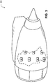
- FIGURE 3 an implementation of the integrated sensor system 112 is shown, according to an illustrative embodiment.
- the sensors 200 are shown disposed into, on, or within an aircraft propulsion package consisting of an engine, aerodynamic cowling (nacelle) and mounting strut ("aircraft propulsion system") 300 .
- nacelle aerodynamic cowling
- aircraft propulsion system 300 mounting strut
- a density with which the sensors 200 are distributed throughout and/or around the aircraft propulsion system 300 can be varied.
- a relatively high density of sensors 200 can be placed in areas where relatively high temperatures are expected to provide a high-resolution measurement capability.
- a relatively low density of sensors 200 can be placed in areas where relatively lower temperatures are expected.
- an area where relatively high temperatures are expected includes the turbine case of the aircraft propulsion system 300
- an area where relatively low temperatures are expected includes the fan compartment of the aircraft propulsion system 300 . It should be understood that this embodiment is illustrative, and should not be construed as being limiting in any way.
- the integrated sensor system 112 and/or the sensors 200 can be embodied in other devices, environments, or structures instead of, or in addition to, the aircraft propulsion system 300 .
- the illustrated embodiment should be understood as being illustrative and should not be construed as being limited in any way. Because aircraft structures are generally understood in the art, the various structures of the illustrated aircraft propulsion system 300 are not described herein in additional detail.
- the sensors 200 can be disposed adjacent to, proximate to, and/or integrated within the various structures of the aircraft propulsion system 300 .
- the sensors 200 can be built into the walls of the aircraft propulsion system 300 , disposed at various points within the aircraft propulsion system 300 such as at or near intakes, at or near nozzles, and/or at other locations that may be determined by personnel designing, servicing, and/or building the aircraft propulsion system 300 , by personnel retrofitting the aircraft propulsion system 300 with the capabilities described herein with regard to the integrated sensor system 112 and/or the monitoring system 102 , and/or by any other entities.
- the illustrated locations of the sensors 200 should be understood as being illustrative, and should not be construed as being limited in any way.
- the sensors 200 can include any suitable sensor devices and/or combinations of sensor devices.
- the sensors 200 include one or more photo sensors, optical sensors, thermal sensors, pressure sensors, and/or combinations thereof.
- Several illustrative embodiments for the sensors 200 are set forth and described in detail below with reference to FIGURES 4A-6B . Because any type of suitable sensors 200 can be used in various embodiments of the concepts and technologies disclosed herein, the various embodiments of the sensors 200 provided herein should be understood as being illustrative, and should not be construed as being limiting in any way.
- FIGURE 4A is a line diagram illustrating aspects of a sensor 200' according to one illustrative embodiment.
- the sensor 200' shown in FIGURE 4A is configured for use in measuring temperature, though this embodiment is illustrative.
- the sensor 200' includes a substrate 400 .
- the substrate 400 can include an engine component, a stand-alone carrier ribbon or other substrate, or any other structure suitable for carrying a thermocouple 402 or other element.
- the substrate 400 is provided by titanium coupon. It should be understood that this embodiment is illustrative, and should not be construed as being limiting in any way.
- the thermocouple 402 can include, as is known, a combination of materials for measuring a voltage generated by heat at or around the thermocouple 402 .
- the thermocouple 402 can include, but is not limited to, a first trace 404 formed from a first material and a second trace 406 formed from a second material.
- the first trace 404 and the second trace 406 can meet or be arranged proximate to one another to facilitate electron transfer between the first and second materials. More particularly, as is known, heat can cause an electron transfer from the first material to the second material, and the resulting voltage can be measured to determine a temperature at or near the thermocouple 402 .
- the thermocouple 402 can be sprayed, printed, or otherwise deposited on the substrate 400 via any suitable process including, for example, using plasma flame spray, atomized jetted deposition, screen printing, ink jetting, and/or other processes.
- the first trace 404 and the second trace 406 form a junction.
- a dielectric trace 408 is provided to separate the electrically conductive thermocouple traces 404 and 406 from the electrically conductive substrate 400 .
- separating the electrically conductive thermocouple traces 404, 406 from the electrically conductive substrate 400 can help prevent electrical shorting between these elements.
- the dielectric trace 408 may be omitted, for example, if the substrate 400 is not electrically conductive.
- the thermocouple 402 is printed onto or otherwise located at a cold side of an engine.
- the thermocouple 402 can be printed onto an outside surface of an engine component. If the thermocouple 402 is disposed at an outside or cold side of an engine, the temperature measured by the thermocouple 402 can be used to estimate a temperature on a hot side or the inside of the component using one or more mathematical formulae or algorithms.
- the thermocouple 402 is printed onto an outside surface of a honeycomb face sheet, and a mathematical algorithm is used to estimate a temperature on the hot side of the component. It should be understood that this embodiment is illustrative, and should not be construed as being limiting in any way.
- an anemometer or other device also can be printed on the cold side of the engine or other component to further compensate for convective heat transfer on the cold side of the component.
- a thermocouple 402 as disclosed herein can be printed onto or located at a hot side or cold side of an engine or component and/or that various structures and/or devices can be used to determine or estimate temperatures at the engine or other component based upon data obtained from or by the thermocouple 402 . Because the thermocouple 402 can be substituted by other types of circuitry or sensors, and because the thermocouple 402 can be used in other structures, it should be understood that the various embodiments discussed above are illustrative, and should not be construed as being limiting in any way.
- the sensor 200' includes, in the illustrated embodiment, six thermocouple junctions 412 and two dielectric patches 414A-B (hereinafter collectively and/or generically referred to as "dielectric patches 414 "). It should be understood that if the substrate 400 is conductive, dielectric traces can be included under any traces and/or in between traces instead of, or in addition to, the illustrated dielectric patches 414 . A shown in FIGURE 4B , a first trace 416 formed from a first thermocouple material can contact a second trace 418 formed a second thermocouple material at one of the junctions 412 .
- the substrate 500 is provided by a flexible material that allows bending and/or form-fitting of the sensor 200" .
- the sensor 200" can be attached to curved or irregularly-shaped surfaces and/or located on or in various structures.
- the substrate 500 can be mechanically attached to a structure using any suitable attachment methods including, but not limited to, adhesive bonding, metallic welding or brazing, plastic welding, ultrasonic welding, laser welding, mechanical fasteners, and/or other suitable processes and/or devices.
- thermocouples 502 or other devices can be printed onto flexible substrates and arranged in a stacked relation, as shown in FIGURE 5A .
- the thermocouples 502 may be electrically isolated from the substrate by depositing a dielectric material, not show, such as Spinel between the thermocouples 502 and substrates 500 .
- the sensor 200" can include a number of substrates 500 , though this is not necessarily the case.
- Various implementations of the sensor 200" are illustrated and described in more detail below, particularly with reference to FIGURES 5C-5E .
- the sensor 200" can include one or more thermocouples 502 and/or a combination of various sensors or devices, if desired.
- the sensor 200" can include multiple devices to provide redundancy and/or to provide various combinations of functionality. It should be understood that this embodiment is illustrative, and should not be construed as being limiting in any way.
- FIGURE 5B is a circuit diagram illustrating additional aspects of the sensor 200" depicted in FIGURE 5A , according to one embodiment.
- a sensor 200" can include a substrate 500 , which can include a flexible or inflexible material, if desired.
- the sensor 200 " can include one or more connectors 510A-B (hereinafter collectively and/or generically referred to as "connectors 510" ).
- the sensor 200" can be connected to one or more devices such as, for example, the monitoring system 102 , via the one or more connectors 510 .
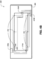
- FIGURE 5C is a line diagram illustrating additional aspects of the sensor 200" depicted in FIGURE 5A .
- FIGURE 5C shows an illustrative implementation of the sensor 200" into an aircraft engine or other structure, according to one illustrative embodiment.
- the sensor 200" can be attached onto a curved or irregularly shaped structure such as, for example, an engine component 520 .
- the engine component 520 includes a number of cellular structures ("cells") 522 , though this is not necessarily the case. As such, it can be appreciated from the arrangement illustrated in FIGURE 5C that the sensor 200" can be attached to a number of cells 522 .
- FIGURE 5C corresponds to an arrangement in which the sensor 200" is attached to an inside surface of the engine component 520 , it should be understood that this is not necessarily the case.
- the sensor 200" can be attached to the outside of the engine component 520 , if desired.
- the illustrated embodiment is illustrative, and should not be construed as being limiting in any way.
- the sensor 200" can be attached to the engine component 520 and/or the cells 522 using any suitable processes or materials.
- the honeycomb panel 530 includes a number of hexagonally-profiled cellular structures ("hex cells") 532 , though this is not necessarily the case.
- the sensor 200" is disposed or used as a septum between two honeycomb core ribbons that can be assembled together to form the hex cells 532 and/or the honeycomb panel 530 .
- the sensor 200" is located at an edge of the honeycomb panel 530 proximate to a hot side of an engine or other structure. It should be understood that this embodiment is illustrative, and should not be construed as being limiting in any way.
- FIGURE 5E is a line diagram illustrating additional aspects of the sensor 200" depicted in FIGURE 5A , according to yet another illustrative embodiment.
- FIGURE 5E shows another illustrative implementation of the sensor 200" implemented into an aircraft engine, a wall, a car engine, or another structure that includes, for example, the honeycomb panel 530 illustrated in FIGURE 5D .
- the sensor 200" can be attached onto the hex cells 532 of the honeycomb panel 530 .
- the sensor 200" is attached to a hot side 540 of the honeycomb panel 530 , though this is not necessarily the case.
- the sensor 200" is located a cold side 542 of the honeycomb panel 530 in addition to, or instead of, the illustrated arrangement.
- FIGURE 5E is illustrative, and should not be construed as being limiting in any way.
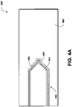
- FIGURE 6 is a line diagram illustrating aspects of a sensor 200'" according to one illustrative embodiment.
- the sensor 200'" can be implemented within an engine or other structure 600 .
- the structure 600 corresponds to an aircraft engine panel, though it should be understood that this embodiment is illustrative.
- the structure 600 includes, in some embodiments, a panel insert cavity ("insert cavity") 606 into which a panel insert 608 is inserted from the cold side 604 such that the panel insert 608 , and/or a portion thereof, is in close proximity to the hot side 602 . It should be understood that the panel insert 608 can be inserted from the hot side 602 , if desired. As such, the illustrated embodiments should be understood as being illustrative, and should not be construed as being limited in any way.
- a signal trace 610 can be disposed at or near the insert cavity 606 .
- the signal trace 610 or a portion thereof, can contact one or more electrical contact pads 612 located at the panel insert 608 .
- one or more dielectric traces 614 can be located proximate to the signal trace 610 to insulate, or at least limit conductivity of, the signal trace 610 .
- the use of the dielectric may, but are not necessarily, useful in enhancing the functionality of the sensor 200"', as is generally understood.
- the panel insert 608 also can include one or more thermocouple materials 616 that can be configured to meet at a thermocouple junction 618 that is to be located at/or near a measurement point 620 within the structure 600 . With the panel insert 608 located within the insert cavity 606 , the temperature at or near the measurement point 620 at the hot side 602 of the structure 600 can be measured via signals measured at the cold side 604 of the structure 600 . It should be understood that this embodiment is illustrative, and should not be construed as being limiting in any way.
- thermocouples While the above discussion of FIGURES 4A-6 has referred to thermocouples as being included within the sensors 200 , 200' , 200" , 200"', it should be understood that thermistors, optical sensors, and/or other sensors can be substituted for, or as, the described thermocouples.
- FIGURE 7 aspects of a method 700 for detecting, monitoring, analyzing, and acting on data obtained with an integrated sensor system as disclosed herein will be described in detail, according to an illustrative embodiment. It should be understood that the operations of the method 700 disclosed herein are not necessarily presented in any particular order and that performance of some or all of the operations in an alternative order(s) is possible and is contemplated. The operations have been presented in the demonstrated order for ease of description and illustration. Operations may be added, omitted, and/or performed simultaneously, without departing from the scope of the appended claims.
- the illustrated method 700 can be ended at any time and need not be performed in its entirety. Some or all operations of the method 700 , and/or substantially equivalent operations, can be performed by execution of computer-readable instructions included on a computer-storage media, as defined herein.
- Computer-readable instructions can be implemented on various system configurations, including single-processor or multiprocessor systems, minicomputers, mainframe computers, personal computers, hand-held computing devices, microprocessor-based, programmable consumer electronics, combinations thereof, and the like.
- the logical operations described herein are implemented (1) as a sequence of computer implemented acts or program modules running on a computing system and/or (2) as interconnected machine logic circuits or circuit modules within the computing system.
- the implementation is a matter of choice dependent on the performance and other requirements of the computing system.
- the logical operations described herein are referred to variously as states, operations, structural devices, acts, or modules. These operations, structural devices, acts, and modules may be implemented in software, in firmware, in special purpose digital logic, and any combination thereof.
- the method 700 is described as being performed by the monitoring system 102 via execution of the monitoring application 106 and/or the reporting application 108 . It should be understood that these embodiments are illustrative, and should not be viewed as being limiting in any way. In particular, it should be understood that any suitable device can be configured to provide the functionality disclosed herein via execution of any suitable programs or modules.
- the method 700 begins at operation 702 , wherein the monitoring system 102 obtains data 114 from one or more of the sensors 200 , 200' , 200" , 200'" and/or the integrated sensor system 112 .
- the sensors 200 , 200' , 200" , 200"' and/or the integrated sensor system 112 can include any type of sensing devices.
- the sensors 200 , 200' , 200" , 200"' and/or the integrated sensor system 112 include or are provided by one or more thermocouples, thermistors, and/or other devices, as well as various sensors or systems associated with the monitored system such as an avionics system of an aircraft or other devices or systems.
- the data 114 obtained in operation 702 is described as being obtained from one or more aircraft systems and by one or more sensors 200 , 200' , 200" , 200"'.
- the data 114 obtained in operation 702 is described herein as being obtained by the monitoring system 102 from one or more aircraft system sensors and/or monitors and by one or more thermocouple devices such as the sensors 200 , 200' , 200" , 200"' .
- the data 114 obtained in operation 702 can include a temperature monitored or measured by the one or more sensors 200 , 200' , 200" , 200"' and/or the integrated sensor system 112 , values corresponding to an ambient temperature or operating temperature measured at or near the aircraft, a thrust level associated with the monitored engine, and/or other data. It should be understood that this embodiment is illustrative, and should not be construed as being limiting in any way.
- the data 114 obtained from the sensors 200 , 200' , 200" , 200"', the integrated sensor system 112 , and/or other devices can be obtained at the monitoring system 102 via direct connections, via networked connections, via communications links, and/or via other devices or links.
- the data 114 can correspond to analog or digital signals generated by or interpreted by the sensors 200 , 200' , 200" , 200"', the integrated sensor system 112 , other devices or systems, and/or the monitoring system 102 , according to various implementations.
- the operational data 116 can include, but is not limited to, one or more thresholds 118 , one or more expected values 120 that are associated with a structure, system, or device monitored by the sensors 200 , 200' , 200" , 200'" and/or the integrated sensor system 112 , and/or historical information or data, and/or current operating characteristics such as altitude, thrust command, airspeed or Mach number.
- the thresholds 118 and/or the expected values 120 can be stored as an array, with an individual value being associated with each sensor location.
- the operational data 116 obtained in operation 704 is described herein as corresponding to at least one threshold 118 such as a temperature threshold associated with the monitored structure, and one or more expected values associated with the sensors 200 , 200' , 200" , 200'" and/or the integrated sensor system 112 .
- a threshold 118 such as a temperature threshold associated with the monitored structure, and one or more expected values associated with the sensors 200 , 200' , 200" , 200'" and/or the integrated sensor system 112 .
- multiple thresholds 118 are stored, wherein each of the thresholds 118 can be associated with a particular sensor, sensor location, and/or other aspects of the integrated sensor system 112 . It should be understood that these embodiments are illustrative, and should not be construed as being limiting in any way.
- the computer architecture 900 includes one or more central processing units 902 ("CPUs"), a system memory 904 that includes a random access memory 906 (“RAM”) and a read-only memory 908 (“ROM”), and a system bus 910 that couples the memory to the CPUs 902 .
- CPUs central processing units 902
- system memory 904 that includes a random access memory 906 (“RAM”) and a read-only memory 908 (“ROM”)
- ROM read-only memory
- the computer architecture 900 also includes a mass storage device 912 .
- the mass storage device 912 may be connected to the CPUs 902 through a mass storage controller (not shown) further connected to the bus 910 .
- the mass storage device 912 and its associated computer-readable media provide non-volatile storage for the computer architecture 900 .
- the mass storage device 912 may store an operating system 914 , various avionics systems and control systems, as well as specific application modules or other program modules, such as the monitoring application 106 , the reporting application 108 , and/or other programs or modules described above with reference to FIGURE 1 .
- the mass storage device 912 also may store data collected or utilized by the various systems and modules including, but not limited to, the operational data 116 , which can include the thresholds 118 , the adjusted thresholds 118' , the expected values 120 , and/or other data. Although not shown in FIGURE 9 , the mass storage device 912 also can store the data 114 and/or the adjusted data values 114' .
- the computer architecture 900 may store programs and data on the mass storage device 912 by transforming the physical state of the mass storage device to reflect the information being stored.
- the specific transformation of physical state may depend on various factors, in different implementations of this disclosure. Examples of such factors may include, but are not limited to, the technology used to implement the mass storage device 912 , whether the mass storage device is characterized as primary or secondary storage, and the like.
- the computer architecture 900 may store information to the mass storage device 912 by issuing instructions through the storage controller to alter the magnetic characteristics of a particular location within a magnetic disk drive device, the reflective or refractive characteristics of a particular location in an optical storage device, or the electrical characteristics of a particular capacitor, transistor, or other discrete component in a solid-state storage device.
- the computer architecture 900 may further read information from the mass storage device 912 by detecting the physical states or characteristics of one or more particular locations within the mass storage device.
- computer-readable media can be any available computer storage media that can be accessed by the computer architecture 900 .
- computer-readable media may include volatile and non-volatile, removable and non-removable media implemented in any method or technology for storage of information such as computer-readable instructions, data structures, program modules, or other data.
- the computer architecture 900 may operate in a networked environment using logical connections to other avionics in the aircraft and/or to systems off-board the aircraft, which may be accessed through a network such as the network 104 .
- the computer architecture 900 may connect to the network 104 through a network interface unit 916 connected to the bus 910 . It should be appreciated that the network interface unit 916 may also be utilized to connect to other types of networks and remote computer systems.
- the computer architecture 900 also may include an input-output controller 918 for receiving input and providing output to aircraft terminals and displays, such as an in-flight display, maintenance access terminal (MAT) or other systems or devices.
- MAT maintenance access terminal
Landscapes
- Engineering & Computer Science (AREA)
- Physics & Mathematics (AREA)
- General Physics & Mathematics (AREA)
- Spectroscopy & Molecular Physics (AREA)
- Chemical & Material Sciences (AREA)
- Combustion & Propulsion (AREA)
- Mechanical Engineering (AREA)
- General Engineering & Computer Science (AREA)
- Human Computer Interaction (AREA)
- Testing Or Calibration Of Command Recording Devices (AREA)
- Arrangements For Transmission Of Measured Signals (AREA)
- Testing And Monitoring For Control Systems (AREA)
Claims (10)
- System, das ein Überwachungssystem (102) aufweist, das zum Ausführen computerausführbarer Anweisungen konfiguriert ist, die zu Folgendem in einem Speicher gespeichert sind:Erhalten von Daten (114) von einem Sensorsystem (112), das mehrere Sensoren (200) aufweist, wobei einer oder mehrere der mehreren Sensoren (200) einen Temperatursensor (200') aufweisen, wobei die überwachte Struktur ein Flugzeugantriebssystem (300) aufweist, wobei der Temperatursensor (200') in mindestens eine Struktur des Flugzeugantriebssystems integriert ist, und wobei die Daten einen Betriebszustand anzeigen und an einer überwachten Struktur durch mindestens einen der mehreren Sensoren erfasst werden;Erhalten von Betriebsdaten (116), die einen Schwellenwert (118) für jeden der mehreren Sensoren und einen erwarteten Wert für jeden der mehreren Sensoren aufweisen;Anpassen der Schwellenwerte (118), die mindestens teilweise auf den Betriebsdaten (116) basieren, um einen eingestellten Schwellenwert (118') zu erhalten, wobei das Anpassen der Schwellenwerte das Erhalten einer Umgebungstemperatur an der überwachten Struktur, das Erhalten einer Schubanpassung im Zusammenhang mit dem mindestens einen der mehreren Sensoren und das Anpassen der Schwellenwerte aufweist, die mindestens teilweise auf der Umgebungstemperatur und der Schubanpassung basieren, um den angepassten Schwellenwert (118') zu erhalten;Vergleichen des erfassten Datenwertes mit dem angepassten Schwellenwert (118'); undBestimmen, ob die überwachte Struktur in einem Alarmzustand arbeitet.
- System nach Anspruch 1, wobei der Temperatursensor (200') auf ein flexibles Substrat (500) gedruckt ist und das flexible Substrat (500) an mindestens einer Oberfläche der überwachten Struktur angebracht ist.
- System nach Anspruch 2, wobei der Sensor ferner ein Anemometer aufweist, das auf die kalte Seite der Struktur gedruckt ist, und wobei das Erhalten der Daten das Erhalten einer Temperaturablesung, die mit dem Temperatursensor erhalten wurde, das Anpassen der erhaltenen Temperatur, die mindestens teilweise auf von dem Anemometer erhaltenen Daten basiert, und das Schätzen einer Temperatur an einer heißen Seite der Struktur, die auf den von dem Temperatursensor (200') und dem Anemometer erhaltenen Daten basiert, aufweist.
- System nach Anspruch 1, wobei das Überwachungssystem ferner zum Ausführen computerausführbarer Anweisungen konfiguriert ist, die zu Folgendem in dem Speicher gespeichert sind:
Erzeugen eines Alarms (122) als Antwort auf das Bestimmen, dass die Struktur in dem Alarmzustand arbeitet;
Bereitstellen des Alarms an einen Alarmempfänger (124); und Speichern der Daten in einer Datenspeichervorrichtung (126). - System nach Anspruch 1, wobei einer oder mehrere der mehreren Sensoren eine Platte, einen Einsatzhohlraum (606), der in der Platte ausgebildet ist, und einen Platteneinsatz (608) aufweisen, der zum selektiven Einsetzen in den Einsatzhohlraum (606) konfiguriert ist.
- Computerimplementiertes Verfahren zum Überwachen einer Struktur, wobei das Verfahren computerimplementierte Operationen für Folgendes aufweist:Erhalten von Daten (114) von mindestens einem mehrerer Temperatursensoren (200) über einen Betriebszustand der überwachten Struktur, wobei die überwachte Struktur ein Flugzeugantriebssystem (300) aufweist, wobei jeder der mehreren Temperatursensoren (200) ein Thermoelement aufweist und wobei jedes der Thermoelemente in mindestens eine Komponente des Flugzeugantriebssystems integriert ist;Erhalten von Betriebsdaten (116), die einen Schwellenwert (118) für den mindestens einen (200') der mehreren Temperatursensoren aufweisen;Anpassen des Schwellenwertes (118), der mindestens teilweise auf den Betriebsdaten (116) basiert, um einen eingestellten Schwellenwert (118') zu erhalten, wobei das Anpassen der Schwellenwerte das Erhalten einer Umgebungstemperatur an der überwachten Struktur, das Erhalten einer Schubanpassung im Zusammenhang mit dem mindestens einen der mehreren Sensoren und das Anpassen der Schwellenwerte aufweist, die mindestens teilweise auf der Umgebungstemperatur und der Schubanpassung basieren, um den angepassten Schwellenwert (118') zu erhalten;Vergleichen des Datenwertes mit dem angepassten Schwellenwert (118'); undBestimmen, ob die Struktur in einem Alarmzustand arbeitet.
- Verfahren nach Anspruch 6, wobei jedes der Thermoelemente auf mindestens eine Oberfläche des Flugzeugantriebssystems (300) gedruckt wird.
- Verfahren nach Anspruch 6, wobei jedes der Thermoelemente auf ein Substrat (500) gedruckt wird, und wobei jedes der Thermoelemente in die mindestens eine Komponente des Flugzeugantriebssystems integriert wird, indem das Substrat (500) an mindestens einer Oberfläche des Flugzeugantriebssystems (300) befestigt wird.
- Verfahren nach Anspruch 6, das ferner das Speichern der Daten in einer Datenspeichervorrichtung (126) in Kommunikation mit dem Überwachungssystem aufweist.
- Verfahren nach Anspruch 6, wobei das Überwachungssystem für computerimplementierte Operationen ferner zum Ausführen computerausführbarer Anweisungen konfiguriert ist, die zu Folgendem in einem Speicher gespeichert sind:Erzeugen eines Alarms (122) als Antwort auf das Bestimmen, dass die Struktur in dem Alarmzustand arbeitet;Bereitstellen des Alarms an einen Alarmempfänger (124), der eine Bedienungsmannschaft aufweist; undSpeichern der Daten in einer Datenspeichervorrichtung (126).
Applications Claiming Priority (1)
| Application Number | Priority Date | Filing Date | Title |
|---|---|---|---|
| US13/242,044 US9127597B2 (en) | 2011-09-23 | 2011-09-23 | Sensor system |
Publications (3)
| Publication Number | Publication Date |
|---|---|
| EP2573367A2 EP2573367A2 (de) | 2013-03-27 |
| EP2573367A3 EP2573367A3 (de) | 2017-11-08 |
| EP2573367B1 true EP2573367B1 (de) | 2019-11-06 |
Family
ID=47257403
Family Applications (1)
| Application Number | Title | Priority Date | Filing Date |
|---|---|---|---|
| EP12185414.5A Active EP2573367B1 (de) | 2011-09-23 | 2012-09-21 | Sensorsystem |
Country Status (6)
| Country | Link |
|---|---|
| US (1) | US9127597B2 (de) |
| EP (1) | EP2573367B1 (de) |
| CN (1) | CN103017819B (de) |
| BR (1) | BR102012023919B1 (de) |
| CA (1) | CA2784022C (de) |
| RU (1) | RU2530316C2 (de) |
Families Citing this family (47)
| Publication number | Priority date | Publication date | Assignee | Title |
|---|---|---|---|---|
| US8878700B2 (en) | 2013-02-18 | 2014-11-04 | The Boeing Company | Aircraft monitoring system |
| US9422869B2 (en) * | 2013-03-13 | 2016-08-23 | General Electric Company | Systems and methods for gas turbine tuning and control |
| CN105122633B (zh) | 2013-04-09 | 2019-04-05 | 热成像雷达有限责任公司 | 步进电机控制系统及方法 |
| WO2014169066A1 (en) * | 2013-04-09 | 2014-10-16 | Thermal Imaging Radar, LLC | Fire detection system |
| KR102248161B1 (ko) | 2013-08-09 | 2021-05-04 | 써멀 이미징 레이다 엘엘씨 | 복수의 가상 장치를 이용하여 열 이미지 데이터를 분석하기 위한 방법들 및 깊이 값들을 이미지 픽셀들에 상관시키기 위한 방법들 |
| US9488533B2 (en) * | 2014-04-11 | 2016-11-08 | Kidde Technologies, Inc. | Self-learning monitoring systems for electrical devices |
| US10064303B2 (en) | 2014-05-20 | 2018-08-28 | The Boeing Company | Integrated wiring system for composite structures |
| US9415882B2 (en) * | 2014-05-22 | 2016-08-16 | Kidde Technologies, Inc. | Overheat sensor system |
| US9354621B2 (en) | 2014-06-16 | 2016-05-31 | General Electric Company | Systems and methods for control of an adaptive-cycle engine with power-thermal management system |
| US9446864B2 (en) | 2014-10-17 | 2016-09-20 | The Boeing Company | NANOSAT electrothermal deployment system |
| US9771874B2 (en) | 2014-11-18 | 2017-09-26 | General Electric Company | Power output and fuel flow based probabilistic control in gas turbine tuning, related control systems, computer program products and methods |
| US9784183B2 (en) | 2014-11-18 | 2017-10-10 | General Electric Company | Power outlet, emissions, fuel flow and water flow based probabilistic control in liquid-fueled gas turbine tuning, related control systems, computer program products and methods |
| US9771877B2 (en) | 2014-11-18 | 2017-09-26 | General Electric Company | Power output and fuel flow based probabilistic control in part load gas turbine tuning, related control systems, computer program products and methods |
| US9771876B2 (en) | 2014-11-18 | 2017-09-26 | General Electric Compnay | Application of probabilistic control in gas turbine tuning with measurement error, related control systems, computer program products and methods |
| US9803561B2 (en) | 2014-11-18 | 2017-10-31 | General Electric Company | Power output and emissions based degraded gas turbine tuning and control systems, computer program products and related methods |
| US9771875B2 (en) | 2014-11-18 | 2017-09-26 | General Electric Company | Application of probabilistic control in gas turbine tuning, related control systems, computer program products and methods |
| US9567106B2 (en) * | 2014-11-21 | 2017-02-14 | Taleris Global Llp | System and method for identifying faults in an aircraft |
| DK3250869T3 (da) * | 2015-01-28 | 2019-07-29 | Ima Life North America Inc | Processtyring under anvendelse af ikke-invasive printede produktsensorer |
| WO2016160794A1 (en) | 2015-03-31 | 2016-10-06 | Thermal Imaging Radar, LLC | Setting different background model sensitivities by user defined regions and background filters |
| USD776181S1 (en) | 2015-04-06 | 2017-01-10 | Thermal Imaging Radar, LLC | Camera |
| US10984338B2 (en) | 2015-05-28 | 2021-04-20 | Raytheon Technologies Corporation | Dynamically updated predictive modeling to predict operational outcomes of interest |
| CN106484199B (zh) * | 2015-08-31 | 2019-08-06 | 小米科技有限责任公司 | 门限设置方法及装置 |
| CN105101277A (zh) * | 2015-09-01 | 2015-11-25 | 中国联合网络通信集团有限公司 | 一种判断监测区域及传感节点异常的方法、装置和系统 |
| US10677170B2 (en) * | 2016-08-05 | 2020-06-09 | Pratt & Whitney Canada Corp. | Apparatus and method for detecting a threshold vibration condition in a gas turbine engine |
| CN106530578B (zh) * | 2016-09-19 | 2018-11-20 | 上海波汇科技股份有限公司 | 一种感温火灾报警系统的阈值处理方法 |
| US10760321B2 (en) * | 2017-04-27 | 2020-09-01 | Rob J. Evans | Thermal door release system |
| CN107121210B (zh) * | 2017-05-19 | 2019-12-03 | 四川成瑞科技有限公司 | 温度监测报警装置、方法及系统 |
| FR3068392A1 (fr) * | 2017-06-29 | 2019-01-04 | Airbus Operations (S.A.S.) | Dispositif de surveillance d'une turbomachine d'un aeronef |
| US9976907B1 (en) | 2017-07-05 | 2018-05-22 | The Boeing Company | Airplane-mounted external fire detection system |
| DE102017211737B4 (de) | 2017-07-10 | 2019-03-28 | Siemens Aktiengesellschaft | Überwachungsvorrichtung und Verfahren zur Überwachung eines Systems |
| JP6912324B2 (ja) * | 2017-08-30 | 2021-08-04 | パナソニック インテレクチュアル プロパティ コーポレーション オブ アメリカPanasonic Intellectual Property Corporation of America | 情報処理方法、情報処理装置及び情報処理プログラム |
| US10574886B2 (en) | 2017-11-02 | 2020-02-25 | Thermal Imaging Radar, LLC | Generating panoramic video for video management systems |
| CN110910530B (zh) * | 2018-09-11 | 2022-06-07 | 陕西千山航空电子有限责任公司 | 一种具有综合告警功能的飞参系统设计方法 |
| US10940959B2 (en) | 2018-10-05 | 2021-03-09 | Simmonds Precision Products, Inc. | Configurable distributed health monitoring system for a landing system |
| DE102019204464A1 (de) * | 2019-03-29 | 2020-10-01 | Airbus Operations Gmbh | Rauch- und brandherddetektionssystem, brandschutzsystem für flugzeuge und verfahren zur detektion von rauch und brandherden |
| DE102019206116B4 (de) * | 2019-04-29 | 2020-11-12 | Diehl Metering Gmbh | Erkennung eines Betriebszustands eines Datensenders durch Überwachung von Umweltparametern |
| US11138433B2 (en) * | 2019-06-07 | 2021-10-05 | The Boeing Company | Cabin experience network with a sensor processing unit |
| US11237067B2 (en) | 2019-08-20 | 2022-02-01 | Kidde Technologies, Inc. | Uncertainty diagnosis for temperature detection systems |
| US11822456B2 (en) * | 2019-09-13 | 2023-11-21 | Accenture Global Solutions Limited | Model control platform |
| CN110972342B (zh) * | 2019-11-13 | 2022-03-15 | 九阳股份有限公司 | 传感器高温报警阈值补偿方法及电磁加热设备 |
| US11601605B2 (en) | 2019-11-22 | 2023-03-07 | Thermal Imaging Radar, LLC | Thermal imaging camera device |
| CN111698654B (zh) * | 2020-05-08 | 2022-09-09 | 上海烟草集团有限责任公司天津卷烟厂 | 基于传感器的无线监测方法、系统、电子设备以及介质 |
| CN112555050B (zh) * | 2020-12-02 | 2022-03-11 | 西安航天动力试验技术研究所 | 一种分布式超音速空气流生成装置运行状态监测及急停方法 |
| CN113108257A (zh) * | 2021-04-22 | 2021-07-13 | 茅台学院 | 一种基于物联网的自激发式消防灭火灯具及报警系统 |
| CN113256843B (zh) * | 2021-05-20 | 2022-05-31 | 中国商用飞机有限责任公司 | 集成式飞行记录设备及方法 |
| US12130187B2 (en) | 2022-06-08 | 2024-10-29 | The Boeing Company | Optical-based fire detection systems and methods |
| US12479589B1 (en) * | 2024-08-29 | 2025-11-25 | Coulson Aviation (USA) Inc | Airplane fuel contaminant detection system |
Citations (3)
| Publication number | Priority date | Publication date | Assignee | Title |
|---|---|---|---|---|
| US4004948A (en) * | 1975-05-29 | 1977-01-25 | The United States Of America As Represented By The Secretary Of The Navy | Paint-on thermocouple |
| US20110222582A1 (en) * | 2008-08-01 | 2011-09-15 | Ramesh Subramanian | Turbine component instrumented to provide thermal measurements |
| WO2011116303A1 (en) * | 2010-03-19 | 2011-09-22 | Micropen Technologies Corporation | Thermocouple device |
Family Cites Families (21)
| Publication number | Priority date | Publication date | Assignee | Title |
|---|---|---|---|---|
| US3071966A (en) * | 1958-12-15 | 1963-01-08 | Bendix Corp | Temperature indicating device corrected for atmospheric pressures at different altitudes |
| US4114442A (en) * | 1976-09-03 | 1978-09-19 | Avicon Development Group | Temperature monitoring system |
| GB2262623B (en) * | 1991-12-17 | 1995-04-26 | Rolls Royce Plc | Aircraft engine management system |
| US6285947B1 (en) * | 1999-10-28 | 2001-09-04 | Brunswick Corporation | Prognostication of future failure of an engine indicator parameter |
| RU2158419C1 (ru) * | 1999-11-04 | 2000-10-27 | Научно-производственное объединение измерительной техники | Датчик температуры |
| US6408259B1 (en) * | 2000-02-01 | 2002-06-18 | General Electric Company | Alert generation for trend performance analysis |
| US6631638B2 (en) * | 2001-01-30 | 2003-10-14 | Rosemount Aerospace Inc. | Fluid flow sensor |
| RU2243134C2 (ru) * | 2002-03-07 | 2004-12-27 | Ростовский Вертолетный Производственный Комплекс - Открытое Акционерное Общество "Роствертол" | Автономная система диагностики летательных аппаратов |
| RU31445U1 (ru) * | 2003-05-05 | 2003-08-10 | Кубанский государственный технологический университет | Термопара для измерения пульсаций поверхностных температур в металлической стенке |
| US7487029B2 (en) * | 2004-05-21 | 2009-02-03 | Pratt & Whitney Canada | Method of monitoring gas turbine engine operation |
| RU2298231C2 (ru) * | 2004-06-22 | 2007-04-27 | Общество с ограниченной ответственностью Научно-технический центр "Системы пожарной безопасности" | Модуль регистрации аварийной ситуации |
| US7142123B1 (en) * | 2005-09-23 | 2006-11-28 | Lawrence Kates | Method and apparatus for detecting moisture in building materials |
| WO2008065213A2 (es) * | 2006-11-29 | 2008-06-05 | Airbus España, S.L. | Métodos y sistemas de simulación térmica para el análisis del fuego en objetos |
| CN101038487A (zh) * | 2007-05-09 | 2007-09-19 | 重庆交通大学 | 一种桥梁监测系统 |
| US8255100B2 (en) * | 2008-02-27 | 2012-08-28 | The Boeing Company | Data-driven anomaly detection to anticipate flight deck effects |
| US8473176B2 (en) * | 2008-04-07 | 2013-06-25 | John S. Youngquist | Aircraft monitoring equipment |
| US7684936B2 (en) * | 2008-05-07 | 2010-03-23 | Simmonds Precision Products, Inc. | Method, apparatus and computer program product for determining a future time of a component |
| CN101763053B (zh) * | 2008-12-26 | 2012-05-02 | 中海网络科技股份有限公司 | 一种移动式桥梁安全检测分析管理系统 |
| US8136988B2 (en) * | 2009-01-15 | 2012-03-20 | The Boeing Company | Methods and systems for passive, wireless temperature monitoring |
| CN201397249Y (zh) * | 2009-04-27 | 2010-02-03 | 北京铁科海联数码技术有限公司 | 桥梁安全检测与评估装置 |
| CN101969613A (zh) * | 2010-08-19 | 2011-02-09 | 西北工业大学 | 一种温室群无线传感器网络控制系统及其控制方法 |
-
2011
- 2011-09-23 US US13/242,044 patent/US9127597B2/en active Active
-
2012
- 2012-07-26 CA CA2784022A patent/CA2784022C/en active Active
- 2012-09-20 RU RU2012140240/08A patent/RU2530316C2/ru active
- 2012-09-21 EP EP12185414.5A patent/EP2573367B1/de active Active
- 2012-09-21 CN CN201210356426.1A patent/CN103017819B/zh active Active
- 2012-09-21 BR BR102012023919-1A patent/BR102012023919B1/pt active IP Right Grant
Patent Citations (3)
| Publication number | Priority date | Publication date | Assignee | Title |
|---|---|---|---|---|
| US4004948A (en) * | 1975-05-29 | 1977-01-25 | The United States Of America As Represented By The Secretary Of The Navy | Paint-on thermocouple |
| US20110222582A1 (en) * | 2008-08-01 | 2011-09-15 | Ramesh Subramanian | Turbine component instrumented to provide thermal measurements |
| WO2011116303A1 (en) * | 2010-03-19 | 2011-09-22 | Micropen Technologies Corporation | Thermocouple device |
Also Published As
| Publication number | Publication date |
|---|---|
| BR102012023919A2 (pt) | 2017-02-21 |
| RU2012140240A (ru) | 2014-03-27 |
| EP2573367A2 (de) | 2013-03-27 |
| CA2784022A1 (en) | 2013-03-23 |
| EP2573367A3 (de) | 2017-11-08 |
| US9127597B2 (en) | 2015-09-08 |
| CN103017819B (zh) | 2017-01-11 |
| CA2784022C (en) | 2017-02-28 |
| RU2530316C2 (ru) | 2014-10-10 |
| US20130079955A1 (en) | 2013-03-28 |
| CN103017819A (zh) | 2013-04-03 |
| BR102012023919B1 (pt) | 2020-10-13 |
Similar Documents
| Publication | Publication Date | Title |
|---|---|---|
| EP2573367B1 (de) | Sensorsystem | |
| EP3500491B1 (de) | Vereisungskontrollsystem | |
| US9359081B2 (en) | Icing condition detection system | |
| EP3739342B1 (de) | Prognostische überwachung komplementärer luftdatensystemsensoren | |
| EP2636599B1 (de) | Supergekühltes Großtropfen-Eis-Erkennungssystem | |
| EP3849906B1 (de) | System und verfahren zur erkennung von eisbildung auf einem körper | |
| EP3567369B1 (de) | Verfahren zur herstellung einer magnetostriktiven oszillator-eisratensonde | |
| Johnson et al. | Experimental investigation of a simplified 3D high lift configuration in support of CFD validation | |
| US10908132B2 (en) | Real-time performance and health monitoring of ice detector systems and estimation of remaining useful life | |
| EP3701240B1 (de) | System und verfahren zur detektion eines kraftstofflecks in einem flugzeug | |
| Kilic et al. | Aircraft air data system fault detection and reconstruction scheme design | |
| US5608627A (en) | Device for supervising the propulsion system of an aircraft | |
| Token | Heat transfer due to shock wave turbulent boundary layer interactions on high speed weapon systems | |
| US11549914B2 (en) | Surface acoustic wave sensors for air data probes | |
| US20230249845A1 (en) | Artificial intelligence and/or machine learning (ai/ml) monitor systems | |
| US20250389745A1 (en) | Piezoelectric deicing for probe faceplate | |
| Zhang et al. | Simulation of fault diagnosis model for managing aeronautical multivariate heterogeneous inputs | |
| Lee et al. | Estimation of engine integrity through fuzzy logic modeling | |
| Kofanov et al. | The Method of Fault Tolerance Evaluation of Reconfigurable Navigation System |
Legal Events
| Date | Code | Title | Description |
|---|---|---|---|
| PUAI | Public reference made under article 153(3) epc to a published international application that has entered the european phase |
Free format text: ORIGINAL CODE: 0009012 |
|
| 17P | Request for examination filed |
Effective date: 20120921 |
|
| AK | Designated contracting states |
Kind code of ref document: A2 Designated state(s): AL AT BE BG CH CY CZ DE DK EE ES FI FR GB GR HR HU IE IS IT LI LT LU LV MC MK MT NL NO PL PT RO RS SE SI SK SM TR |
|
| AX | Request for extension of the european patent |
Extension state: BA ME |
|
| PUAL | Search report despatched |
Free format text: ORIGINAL CODE: 0009013 |
|
| AK | Designated contracting states |
Kind code of ref document: A3 Designated state(s): AL AT BE BG CH CY CZ DE DK EE ES FI FR GB GR HR HU IE IS IT LI LT LU LV MC MK MT NL NO PL PT RO RS SE SI SK SM TR |
|
| AX | Request for extension of the european patent |
Extension state: BA ME |
|
| RIC1 | Information provided on ipc code assigned before grant |
Ipc: F02C 9/28 20060101AFI20171003BHEP |
|
| STAA | Information on the status of an ep patent application or granted ep patent |
Free format text: STATUS: EXAMINATION IS IN PROGRESS |
|
| 17Q | First examination report despatched |
Effective date: 20180925 |
|
| GRAP | Despatch of communication of intention to grant a patent |
Free format text: ORIGINAL CODE: EPIDOSNIGR1 |
|
| STAA | Information on the status of an ep patent application or granted ep patent |
Free format text: STATUS: GRANT OF PATENT IS INTENDED |
|
| INTG | Intention to grant announced |
Effective date: 20190417 |
|
| GRAS | Grant fee paid |
Free format text: ORIGINAL CODE: EPIDOSNIGR3 |
|
| GRAA | (expected) grant |
Free format text: ORIGINAL CODE: 0009210 |
|
| STAA | Information on the status of an ep patent application or granted ep patent |
Free format text: STATUS: THE PATENT HAS BEEN GRANTED |
|
| AK | Designated contracting states |
Kind code of ref document: B1 Designated state(s): AL AT BE BG CH CY CZ DE DK EE ES FI FR GB GR HR HU IE IS IT LI LT LU LV MC MK MT NL NO PL PT RO RS SE SI SK SM TR |
|
| REG | Reference to a national code |
Ref country code: GB Ref legal event code: FG4D |
|
| REG | Reference to a national code |
Ref country code: CH Ref legal event code: EP Ref country code: AT Ref legal event code: REF Ref document number: 1199008 Country of ref document: AT Kind code of ref document: T Effective date: 20191115 |
|
| REG | Reference to a national code |
Ref country code: IE Ref legal event code: FG4D |
|
| REG | Reference to a national code |
Ref country code: DE Ref legal event code: R096 Ref document number: 602012065398 Country of ref document: DE |
|
| REG | Reference to a national code |
Ref country code: NL Ref legal event code: MP Effective date: 20191106 |
|
| REG | Reference to a national code |
Ref country code: LT Ref legal event code: MG4D |
|
| PG25 | Lapsed in a contracting state [announced via postgrant information from national office to epo] |
Ref country code: LV Free format text: LAPSE BECAUSE OF FAILURE TO SUBMIT A TRANSLATION OF THE DESCRIPTION OR TO PAY THE FEE WITHIN THE PRESCRIBED TIME-LIMIT Effective date: 20191106 Ref country code: SE Free format text: LAPSE BECAUSE OF FAILURE TO SUBMIT A TRANSLATION OF THE DESCRIPTION OR TO PAY THE FEE WITHIN THE PRESCRIBED TIME-LIMIT Effective date: 20191106 Ref country code: NL Free format text: LAPSE BECAUSE OF FAILURE TO SUBMIT A TRANSLATION OF THE DESCRIPTION OR TO PAY THE FEE WITHIN THE PRESCRIBED TIME-LIMIT Effective date: 20191106 Ref country code: ES Free format text: LAPSE BECAUSE OF FAILURE TO SUBMIT A TRANSLATION OF THE DESCRIPTION OR TO PAY THE FEE WITHIN THE PRESCRIBED TIME-LIMIT Effective date: 20191106 Ref country code: LT Free format text: LAPSE BECAUSE OF FAILURE TO SUBMIT A TRANSLATION OF THE DESCRIPTION OR TO PAY THE FEE WITHIN THE PRESCRIBED TIME-LIMIT Effective date: 20191106 Ref country code: BG Free format text: LAPSE BECAUSE OF FAILURE TO SUBMIT A TRANSLATION OF THE DESCRIPTION OR TO PAY THE FEE WITHIN THE PRESCRIBED TIME-LIMIT Effective date: 20200206 Ref country code: FI Free format text: LAPSE BECAUSE OF FAILURE TO SUBMIT A TRANSLATION OF THE DESCRIPTION OR TO PAY THE FEE WITHIN THE PRESCRIBED TIME-LIMIT Effective date: 20191106 Ref country code: GR Free format text: LAPSE BECAUSE OF FAILURE TO SUBMIT A TRANSLATION OF THE DESCRIPTION OR TO PAY THE FEE WITHIN THE PRESCRIBED TIME-LIMIT Effective date: 20200207 Ref country code: PL Free format text: LAPSE BECAUSE OF FAILURE TO SUBMIT A TRANSLATION OF THE DESCRIPTION OR TO PAY THE FEE WITHIN THE PRESCRIBED TIME-LIMIT Effective date: 20191106 Ref country code: NO Free format text: LAPSE BECAUSE OF FAILURE TO SUBMIT A TRANSLATION OF THE DESCRIPTION OR TO PAY THE FEE WITHIN THE PRESCRIBED TIME-LIMIT Effective date: 20200206 Ref country code: PT Free format text: LAPSE BECAUSE OF FAILURE TO SUBMIT A TRANSLATION OF THE DESCRIPTION OR TO PAY THE FEE WITHIN THE PRESCRIBED TIME-LIMIT Effective date: 20200306 |
|
| PG25 | Lapsed in a contracting state [announced via postgrant information from national office to epo] |
Ref country code: HR Free format text: LAPSE BECAUSE OF FAILURE TO SUBMIT A TRANSLATION OF THE DESCRIPTION OR TO PAY THE FEE WITHIN THE PRESCRIBED TIME-LIMIT Effective date: 20191106 Ref country code: RS Free format text: LAPSE BECAUSE OF FAILURE TO SUBMIT A TRANSLATION OF THE DESCRIPTION OR TO PAY THE FEE WITHIN THE PRESCRIBED TIME-LIMIT Effective date: 20191106 Ref country code: IS Free format text: LAPSE BECAUSE OF FAILURE TO SUBMIT A TRANSLATION OF THE DESCRIPTION OR TO PAY THE FEE WITHIN THE PRESCRIBED TIME-LIMIT Effective date: 20200306 |
|
| PG25 | Lapsed in a contracting state [announced via postgrant information from national office to epo] |
Ref country code: AL Free format text: LAPSE BECAUSE OF FAILURE TO SUBMIT A TRANSLATION OF THE DESCRIPTION OR TO PAY THE FEE WITHIN THE PRESCRIBED TIME-LIMIT Effective date: 20191106 |
|
| PG25 | Lapsed in a contracting state [announced via postgrant information from national office to epo] |
Ref country code: CZ Free format text: LAPSE BECAUSE OF FAILURE TO SUBMIT A TRANSLATION OF THE DESCRIPTION OR TO PAY THE FEE WITHIN THE PRESCRIBED TIME-LIMIT Effective date: 20191106 Ref country code: RO Free format text: LAPSE BECAUSE OF FAILURE TO SUBMIT A TRANSLATION OF THE DESCRIPTION OR TO PAY THE FEE WITHIN THE PRESCRIBED TIME-LIMIT Effective date: 20191106 Ref country code: DK Free format text: LAPSE BECAUSE OF FAILURE TO SUBMIT A TRANSLATION OF THE DESCRIPTION OR TO PAY THE FEE WITHIN THE PRESCRIBED TIME-LIMIT Effective date: 20191106 Ref country code: EE Free format text: LAPSE BECAUSE OF FAILURE TO SUBMIT A TRANSLATION OF THE DESCRIPTION OR TO PAY THE FEE WITHIN THE PRESCRIBED TIME-LIMIT Effective date: 20191106 |
|
| REG | Reference to a national code |
Ref country code: DE Ref legal event code: R097 Ref document number: 602012065398 Country of ref document: DE |
|
| REG | Reference to a national code |
Ref country code: AT Ref legal event code: MK05 Ref document number: 1199008 Country of ref document: AT Kind code of ref document: T Effective date: 20191106 |
|
| PG25 | Lapsed in a contracting state [announced via postgrant information from national office to epo] |
Ref country code: SK Free format text: LAPSE BECAUSE OF FAILURE TO SUBMIT A TRANSLATION OF THE DESCRIPTION OR TO PAY THE FEE WITHIN THE PRESCRIBED TIME-LIMIT Effective date: 20191106 Ref country code: SM Free format text: LAPSE BECAUSE OF FAILURE TO SUBMIT A TRANSLATION OF THE DESCRIPTION OR TO PAY THE FEE WITHIN THE PRESCRIBED TIME-LIMIT Effective date: 20191106 |
|
| PLBE | No opposition filed within time limit |
Free format text: ORIGINAL CODE: 0009261 |
|
| STAA | Information on the status of an ep patent application or granted ep patent |
Free format text: STATUS: NO OPPOSITION FILED WITHIN TIME LIMIT |
|
| 26N | No opposition filed |
Effective date: 20200807 |
|
| PG25 | Lapsed in a contracting state [announced via postgrant information from national office to epo] |
Ref country code: AT Free format text: LAPSE BECAUSE OF FAILURE TO SUBMIT A TRANSLATION OF THE DESCRIPTION OR TO PAY THE FEE WITHIN THE PRESCRIBED TIME-LIMIT Effective date: 20191106 Ref country code: SI Free format text: LAPSE BECAUSE OF FAILURE TO SUBMIT A TRANSLATION OF THE DESCRIPTION OR TO PAY THE FEE WITHIN THE PRESCRIBED TIME-LIMIT Effective date: 20191106 |
|
| PG25 | Lapsed in a contracting state [announced via postgrant information from national office to epo] |
Ref country code: IT Free format text: LAPSE BECAUSE OF FAILURE TO SUBMIT A TRANSLATION OF THE DESCRIPTION OR TO PAY THE FEE WITHIN THE PRESCRIBED TIME-LIMIT Effective date: 20191106 |
|
| PG25 | Lapsed in a contracting state [announced via postgrant information from national office to epo] |
Ref country code: MC Free format text: LAPSE BECAUSE OF FAILURE TO SUBMIT A TRANSLATION OF THE DESCRIPTION OR TO PAY THE FEE WITHIN THE PRESCRIBED TIME-LIMIT Effective date: 20191106 |
|
| REG | Reference to a national code |
Ref country code: CH Ref legal event code: PL |
|
| REG | Reference to a national code |
Ref country code: BE Ref legal event code: MM Effective date: 20200930 |
|
| PG25 | Lapsed in a contracting state [announced via postgrant information from national office to epo] |
Ref country code: LU Free format text: LAPSE BECAUSE OF NON-PAYMENT OF DUE FEES Effective date: 20200921 |
|
| PG25 | Lapsed in a contracting state [announced via postgrant information from national office to epo] |
Ref country code: IE Free format text: LAPSE BECAUSE OF NON-PAYMENT OF DUE FEES Effective date: 20200921 Ref country code: LI Free format text: LAPSE BECAUSE OF NON-PAYMENT OF DUE FEES Effective date: 20200930 Ref country code: BE Free format text: LAPSE BECAUSE OF NON-PAYMENT OF DUE FEES Effective date: 20200930 Ref country code: CH Free format text: LAPSE BECAUSE OF NON-PAYMENT OF DUE FEES Effective date: 20200930 |
|
| PG25 | Lapsed in a contracting state [announced via postgrant information from national office to epo] |
Ref country code: TR Free format text: LAPSE BECAUSE OF FAILURE TO SUBMIT A TRANSLATION OF THE DESCRIPTION OR TO PAY THE FEE WITHIN THE PRESCRIBED TIME-LIMIT Effective date: 20191106 Ref country code: MT Free format text: LAPSE BECAUSE OF FAILURE TO SUBMIT A TRANSLATION OF THE DESCRIPTION OR TO PAY THE FEE WITHIN THE PRESCRIBED TIME-LIMIT Effective date: 20191106 Ref country code: CY Free format text: LAPSE BECAUSE OF FAILURE TO SUBMIT A TRANSLATION OF THE DESCRIPTION OR TO PAY THE FEE WITHIN THE PRESCRIBED TIME-LIMIT Effective date: 20191106 |
|
| PG25 | Lapsed in a contracting state [announced via postgrant information from national office to epo] |
Ref country code: MK Free format text: LAPSE BECAUSE OF FAILURE TO SUBMIT A TRANSLATION OF THE DESCRIPTION OR TO PAY THE FEE WITHIN THE PRESCRIBED TIME-LIMIT Effective date: 20191106 |
|
| P01 | Opt-out of the competence of the unified patent court (upc) registered |
Effective date: 20230516 |
|
| PGFP | Annual fee paid to national office [announced via postgrant information from national office to epo] |
Ref country code: DE Payment date: 20250929 Year of fee payment: 14 |
|
| PGFP | Annual fee paid to national office [announced via postgrant information from national office to epo] |
Ref country code: GB Payment date: 20250929 Year of fee payment: 14 |
|
| PGFP | Annual fee paid to national office [announced via postgrant information from national office to epo] |
Ref country code: FR Payment date: 20250925 Year of fee payment: 14 |