EP2573379A2 - Brennstoffzufuhrsystem - Google Patents
Brennstoffzufuhrsystem Download PDFInfo
- Publication number
- EP2573379A2 EP2573379A2 EP20120185948 EP12185948A EP2573379A2 EP 2573379 A2 EP2573379 A2 EP 2573379A2 EP 20120185948 EP20120185948 EP 20120185948 EP 12185948 A EP12185948 A EP 12185948A EP 2573379 A2 EP2573379 A2 EP 2573379A2
- Authority
- EP
- European Patent Office
- Prior art keywords
- fuel
- valve
- passageway
- pump
- rail
- Prior art date
- Legal status (The legal status is an assumption and is not a legal conclusion. Google has not performed a legal analysis and makes no representation as to the accuracy of the status listed.)
- Granted
Links
Images


Classifications
-
- F—MECHANICAL ENGINEERING; LIGHTING; HEATING; WEAPONS; BLASTING
- F02—COMBUSTION ENGINES; HOT-GAS OR COMBUSTION-PRODUCT ENGINE PLANTS
- F02M—SUPPLYING COMBUSTION ENGINES IN GENERAL WITH COMBUSTIBLE MIXTURES OR CONSTITUENTS THEREOF
- F02M63/00—Other fuel-injection apparatus having pertinent characteristics not provided for in groups F02M39/00 - F02M57/00 or F02M67/00; Details, component parts, or accessories of fuel-injection apparatus, not provided for in, or of interest apart from, the apparatus of groups F02M39/00 - F02M61/00 or F02M67/00; Combination of fuel pump with other devices, e.g. lubricating oil pump
- F02M63/02—Fuel-injection apparatus having several injectors fed by a common pumping element, or having several pumping elements feeding a common injector; Fuel-injection apparatus having provisions for cutting-out pumps, pumping elements, or injectors; Fuel-injection apparatus having provisions for variably interconnecting pumping elements and injectors alternatively
- F02M63/0225—Fuel-injection apparatus having a common rail feeding several injectors ; Means for varying pressure in common rails; Pumps feeding common rails
- F02M63/0265—Pumps feeding common rails
- F02M63/027—More than one high pressure pump feeding a single common rail
-
- F—MECHANICAL ENGINEERING; LIGHTING; HEATING; WEAPONS; BLASTING
- F02—COMBUSTION ENGINES; HOT-GAS OR COMBUSTION-PRODUCT ENGINE PLANTS
- F02M—SUPPLYING COMBUSTION ENGINES IN GENERAL WITH COMBUSTIBLE MIXTURES OR CONSTITUENTS THEREOF
- F02M37/00—Apparatus or systems for feeding liquid fuel from storage containers to carburettors or fuel-injection apparatus; Arrangements for purifying liquid fuel specially adapted for, or arranged on, internal-combustion engines
- F02M37/0011—Constructional details; Manufacturing or assembly of elements of fuel systems; Materials therefor
- F02M37/0041—Means for damping pressure pulsations
-
- F—MECHANICAL ENGINEERING; LIGHTING; HEATING; WEAPONS; BLASTING
- F02—COMBUSTION ENGINES; HOT-GAS OR COMBUSTION-PRODUCT ENGINE PLANTS
- F02M—SUPPLYING COMBUSTION ENGINES IN GENERAL WITH COMBUSTIBLE MIXTURES OR CONSTITUENTS THEREOF
- F02M45/00—Fuel-injection apparatus characterised by having a cyclic delivery of specific time/pressure or time/quantity relationship
- F02M45/02—Fuel-injection apparatus characterised by having a cyclic delivery of specific time/pressure or time/quantity relationship with each cyclic delivery being separated into two or more parts
- F02M45/04—Fuel-injection apparatus characterised by having a cyclic delivery of specific time/pressure or time/quantity relationship with each cyclic delivery being separated into two or more parts with a small initial part, e.g. initial part for partial load and initial and main part for full load
- F02M45/08—Injectors peculiar thereto
- F02M45/086—Having more than one injection-valve controlling discharge orifices
-
- F—MECHANICAL ENGINEERING; LIGHTING; HEATING; WEAPONS; BLASTING
- F02—COMBUSTION ENGINES; HOT-GAS OR COMBUSTION-PRODUCT ENGINE PLANTS
- F02M—SUPPLYING COMBUSTION ENGINES IN GENERAL WITH COMBUSTIBLE MIXTURES OR CONSTITUENTS THEREOF
- F02M55/00—Fuel-injection apparatus characterised by their fuel conduits or their venting means; Arrangements of conduits between fuel tank and pump F02M37/00
- F02M55/04—Means for damping vibrations or pressure fluctuations in injection pump inlets or outlets
-
- F—MECHANICAL ENGINEERING; LIGHTING; HEATING; WEAPONS; BLASTING
- F02—COMBUSTION ENGINES; HOT-GAS OR COMBUSTION-PRODUCT ENGINE PLANTS
- F02M—SUPPLYING COMBUSTION ENGINES IN GENERAL WITH COMBUSTIBLE MIXTURES OR CONSTITUENTS THEREOF
- F02M63/00—Other fuel-injection apparatus having pertinent characteristics not provided for in groups F02M39/00 - F02M57/00 or F02M67/00; Details, component parts, or accessories of fuel-injection apparatus, not provided for in, or of interest apart from, the apparatus of groups F02M39/00 - F02M61/00 or F02M67/00; Combination of fuel pump with other devices, e.g. lubricating oil pump
- F02M63/02—Fuel-injection apparatus having several injectors fed by a common pumping element, or having several pumping elements feeding a common injector; Fuel-injection apparatus having provisions for cutting-out pumps, pumping elements, or injectors; Fuel-injection apparatus having provisions for variably interconnecting pumping elements and injectors alternatively
- F02M63/0225—Fuel-injection apparatus having a common rail feeding several injectors ; Means for varying pressure in common rails; Pumps feeding common rails
- F02M63/0275—Arrangement of common rails
- F02M63/0285—Arrangement of common rails having more than one common rail
Definitions
- the present invention relates generally to fuel delivery systems and, more particularly, fuel delivery systems for a direct injection internal combustion engine.
- At least one fuel injector is associated with each combustion chamber in the engine. Furthermore, the fuel injectors are mounted such that the fuel injector injects fuel directly into the combustion chamber rather than upstream from the intake valves as in the previously known multipoint fuel injectors. This direct injection of the fuel into the combustion chamber results in increased engine performance and enhanced fuel economy.
- a fuel pump provides pressurized fuel to a fuel rail.
- Two or more fuel injectors are fluidly connected with the fuel rail.
- a separate fuel rail is provided for each bank of engine combustion chambers.
- One of the main advantages of a direct injection fuel delivery system is that it offers better atomization and thereby complete combustion of the fuel since it is injected directly into the combustion chamber at a high pressure. These pressures are on a magnitude of 10-20 times the pressurization required for fuel rails in the previously known multipoint fuel delivery systems.
- a still further disadvantage of the previously known direct injection internal combustion engines is that it has oftentimes been necessary to provide two fuel injectors for each combustion chamber.
- One fuel injector is used during low engine speed when a relatively low amount of fuel is required.
- the second injector is designed to inject larger quantities of fuel into its associated internal combustion chamber at higher engine speeds. Both injectors are controlled by the engine control unit for the vehicle.
- pulse width modulation PWM is used to activate the proper fuel injector valve between an open and a closed position.
- the present invention provides a fuel delivery system which overcomes the above mentioned disadvantages of the previously known systems.
- a first and second fuel rail are provided with each fuel rail associated with one bank of engine combustion chambers.
- Each fuel rail includes an elongated passageway which is fluidly connected to a plurality of fuel injectors for each fuel rail.
- a first fuel pump having a first pumping cycle has an inlet connected to a fuel source, such as the fuel tank, and an outlet fluidly connected to the fuel passageway in the first fuel rail.
- a single fuel pump having a second pumping cycle is provided in which the inlet of the second fuel pump is fluidly connected to the fuel source while the outlet from the second fuel pump is fluidly connected to the fuel passageway in the second fuel rail.
- a crossover pipe fluidly connects the outlets of the first and second pumps together. Furthermore, a pressure relief valve is preferably provided between a midpoint of the crossover pipe and the inlet for at least one and preferably both of the fuel pumps.
- Each pumping cycle of the first and second pumps has an intake stroke and a pumping stroke.
- the intake stroke of the first pump coincides with the pumping stroke of the second pump and vice versa. In doing so, pressure pulsations, together with the resultant noise, in the fuel delivery system are reduced.
- Noise from the fuel system caused by pressure pulsations is alternatively reduced by providing a plurality of fluid reservoirs so that one fluid reservoir is associated with each of the fuel injectors.
- the fluid reservoir may be positioned either fluidly in series between the fuel rail and each fuel injector.
- a fluid reservoir is open to the fuel passageway in the fuel rail at a position aligned with its associated fuel injector, but on the side of the fuel rail opposite from the fuel injector.
- a fuel reservoir may also be provided in series in the associated fuel rail. (This is referring to FIG. 5 ).
- An improved fuel injector having an elongated body with an inlet end and an outlet end.
- a fluid passageway extends between and interconnects the inlet end with its outlet end.
- a valve seat is disposed across the outlet end of the body.
- the valve seat has both a first and second set of fluid passageways wherein each set includes at least one fluid passageway.
- a first valve provides fuel for high speed operation and is movably mounted between an open and a closed position in the body. In its closed position, the first valve engages the valve seat and closes the first set of passages. Conversely, in the open position the first valve separates from the valve seat and opens the first set of passages so that fuel flows from the inlet end and to the outlet end of the body and out through the first set of passages.
- a second valve provides fuel at low engine speed and is also movably mounted in the body and preferably movably mounted within the first valve between an open and a closed position. In the closed position, the second valve engages the valve seat and closes the second set of orifices. Conversely, in its open position, the second valve separates from the valve seat and opens the second set of orifices to allow fuel flow from the inlet, through the body passageway, and out through the second set of orifices.
- An actuator such as an electromagnet
- An actuator is contained within the body and selectively energized in a pulse width modulation mode by the engine control unit.
- the electromagnet moves the first valve against the force of a compression spring to move the valve from its closed and to its open position.
- a second current value to the electromagnet opens only the second valve while leaving the first valve in a closed position.
- the second current value is less than the first current value.
- FIG. 1 is a block diagrammatic view illustrating a fuel system of the present invention
- FIG. 2 is a fragmentary longitudinal sectional view illustrating a portion of the fuel system of the present invention
- FIG. 3 is a diagrammatic view of a fuel pump of the system of the present invention.
- FIG. 4 is a graph illustrating the effect of the crossover pipe and out of phase fuel pumps versus a baseline model
- FIG. 5 is a longitudinal sectional view illustrating one preferred embodiment of a fuel rail of the present invention.
- FIG. 6 is a view similar to FIG. 5 , but illustrating another preferred embodiment of the fuel rail
- FIG. 7 is a view similar to both FIGS. 5 and 6 and illustrating yet another preferred embodiment of the fuel rail
- FIG. 8 is a graph illustrating the effects of the fuel rail of FIG. 5 ;
- FIG. 9 is a graph illustrating the effects of the fuel rail of FIG. 6 ;
- FIG. 10 is a graph illustrating the effects of the fuel rail of FIG. 7 ;
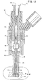
- FIG. 11 is a longitudinal sectional view illustrating a preferred embodiment of a fuel injector with both valves in the closed position
- FIG. 12 is a longitudinal sectional view of the fuel injector but with the second valve in an open position
- FIG. 13 is an end view illustrating the valve seat
- FIG. 14 is a fragmentary sectional view illustrating the first valve in an open position
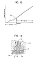
- FIG. 15 is a graph illustrating the operation of the fuel injector of FIGS. 11 and 12 ;
- FIG. 16 is an enlarged view of circle 16-16 in FIG. 12 .
- FIGS. 1 and 2 a diagrammatic view of a fuel system 20 in accordance with the present invention is shown.
- the fuel system includes a pair of spaced apart fuel rails 22 and 23 and at least two fuel injectors 24 associated with each rail.
- each fuel rail 22 and 23 includes an elongated fuel passageway 26 having an inlet end 28.
- a fuel cup 30 is provided for each fuel injector 24. This fuel cup 30 is open to the fuel passageway 26 and its associated fuel rail 22 or 23 to thereby provide fuel to the fuel injector 24.
- a first fuel pump 32 has an inlet 34 to a fuel source 36, such as the fuel tank.
- An outlet 38 from the fuel pump 32 is fluidly connected by a fuel supply line 40 to the inlet end 28 of the first fuel rail 22.
- a second high pressure pump 42 has its inlet 44 fluidly connected to the fuel source 36 and an outlet 46 fluidly connected by a fuel line 48 to the inlet end 28 of the second fuel rail 23.
- both of the high pressure fuel pumps 32 and 42 are substantially identical to each other in construction. As such, only the fuel pump 32 will be described, it being understood that a like description shall also apply to the second fuel pump 42.
- the fuel pump 32 includes a housing 50 having a pump chamber 52.
- a piston 54 is reciprocally mounted within the pump chamber 52 and is reciprocally driven by a cam 56 driven by the engine.
- a one-way valve 58 is fluidly connected in series between the pump chamber 52 and the outlet 38. Consequently, during the pump stroke of the pump cycle, the piston 54 moves upwardly as viewed in FIG. 3 thus forcing fuel out through the one-way valve 58, through the pump outlet 38, and to the first fuel rail 22.
- a one-way valve 60 is connected in series with the inlet 34 for the pump 32.
- the valve 60 thus allows fuel flow only through the inlet and into the pump chamber 52. Consequently, during an intake stroke, i.e. when the piston 54 moves downwardly within the pump chamber 52, the piston 54 inducts fuel through the one-way valve 60 and into the pump chamber 52.
- Each pump cycle furthermore, consists of a single pump stroke and intake stroke.
- the second fuel pump 42 is substantially identical to the first fuel pump 32.
- the cam associated with the second fuel pump 42 is angularly displaced relative to the cam 56 so that the intake stroke of the first pump 32 coincides with the pump stroke of the second pump 42 and, likewise, the pump stroke of the first pump 32 coincides with the intake stroke of the second pump 42.
- a crossover pipe 62 fluidly connects the outlets 38 and 46 of the pumps 32 and 42, respectively.
- This crossover pipe 62 thus effectively dampens the pressure pulsations since the pressure pulsations pass in part from one of the pumps 32 or 42 during the pump cycle through the crossover pipe 62 and to the other pump during its intake cycle.
- a pressure relief valve 64 is also fluidly connected between a midpoint of the crossover pipe 62 and at least one, and preferably both inlets 34 and 44 of the pumps 32 and 42, respectively. This pressure relief valve 64 prevents build up of excess pressure in the fuel system.
- the net effect of utilizing both the crossover pipe 62 as well as the out of phase fuel pumps 32 and 42 is shown in graph 70 versus the same configuration for a simple model without the crossover pipe and in phase fuel pumps 32 and 42 as shown in graph 72 (this is referred to as the baseline mode).
- the peaks to the valleys pressure difference of the graph 70 i.e. the crossover pipe 62 and out of phase fuel pumps 32 and 42, is much less than the peak to valley pressure difference of the baseline model without the crossover pipe 62 and with the fuel pumps 32 and 42 in phase.
- pressure pulsation is defined as the magnitude difference between the peak and valley pressure values. It is desired to minimize this magnitude.
- the fuel rail 100 includes an elongated fuel passageway which is fluidly connected at an inlet end 104 to the outlet of a fuel pump. At least two, and more typically three or four, fuel injectors 24 are mounted to the fuel rail 100 at longitudinally spaced intervals along the fuel rail 100. Each fuel injector 24 is fluidly open to the fuel rail passageway 102.
- Each fuel reservoir 106 is associated with each fuel injector 24.
- Each fuel reservoir 106 has a cross-sectional area, i.e. as viewed along the length of the fuel rail 100, greater than the cross-sectional area of the fuel passageway 102.
- Each reservoir 106 also is preferably annular in shape and extends around substantially the entire fuel rail 100. As such, the reservoir 106 is fluidly positioned in part in series between the fuel passageway 102 and the fuel injectors 24 and in part on the side of the fuel rail 100 opposite from the fuel injector 24.
- the reservoirs 106 serve to dampen pressure pulsations from the fuel injector. In doing so, the reservoirs 106 reduce the noise of the fuel delivery system, especially at low engine speeds.
- a still further preferred embodiment of a fuel rail 110 is shown.
- a reservoir 106 having a greater cross-sectional area than the rail fuel passageway 102 is also shown.
- the fuel rail 110 differs from the fuel rail 100 ( FIG. 5 ) in that the fuel reservoir 106 extends outwardly from the fuel passageway 102 on the side of the fuel rail 110 opposite from its associated fuel injector 24.
- a reservoir 106 is associated with each fuel injector 24.
- Each reservoir 106 has a cross-sectional area as viewed longitudinally along the fuel rail larger than the fuel rail passageway 102.
- the reservoirs 106 are fluidly positioned in series between the fuel passageway for the fuel rail 120 and its associated fuel injector 24.
- the dimensions and volume of the reservoirs in FIGS. 5-7 will vary depending on many factors including, for example, engine performance requirements. However, as an example only and assuming that the diameter of the rail passageway 102 is D and the spacing of the fuel injectors is in the range of 6-9D, the longitudinal length of each reservoir is in the range of 2.5-4D. Typically, the length of the fuel connector from the pump to the fuel rail is in the range of 30-40D and its diameter is in the range of 0.25-0.5D.
- the reservoir 106 effectively dampens fuel pressure pulsations that otherwise occur in the fuel rail 100. This is particularly true for low engine speeds.
- the pressure profile corresponding to FIG. 5 is shown in FIG. 8 .
- graph 130 depicts the pressure where the reservoir 106 is contained in the fuel rail as shown in FIG. 5 versus a baseline illustrated in graph 132 in which the reservoir is eliminated.
- FIG. 9 depicts graph 134 which corresponds with the fuel rail 110 in FIG. 6 .
- the peak to valley differences of the graph 134 are substantially less than the baseline 132 in which the reservoirs 106 are eliminated.
- FIG. 10 shows graph 136 which corresponds to the fuel rail 120 shown in FIG. 7 .
- the peak to valley differences of the graph 136 are significantly less than the peak to valley differences of the baseline graph 132.
- the fuel injector 140 includes an elongated body 142 having an inlet end 144 and an outlet end 146. As in all direct injection engines, the outlet 146 is open to a combustion chamber 148.
- a longitudinally or axially extending fuel passageway 150 fluidly connects the inlet end 144 to the outlet end 146 of the body 142.
- the outlet end 146 of the body 142 is covered by a valve seat 152 best shown in FIGS. 12 and 13 .
- valve seat 152 extends across and closes the outlet end 146 of the body 142, two sets of orifices are provided through the valve seat 152 to allow fuel to pass from the fuel passageway 150 out through the valve seat 152. As best shown in FIG. 13 , these orifices are arranged in two sets.
- the first set 154 includes a plurality of annularly spaced through orifices in the valve seat 152.
- the second set 156 of orifices preferably includes a single through orifice in the center of the valve seat 152.
- an elongated first valve 160 which controls fuel delivery during high engine speeds is longitudinally slidably mounted in said body 142 and movable between a closed position, illustrated in FIG. 11 , and an open position, illustrated in FIG. 14 .
- the first valve 160 engages the valve seat 152 and closes the first set 154 and second set 156 of through orifices.
- the open position FIG.
- the first valve 160 is retracted from the valve seat 152 thus exposing the first set 154 and second set 156 of through orifices in the valve seat 152 and allowing fuel to flow from the passageway 150 through a mixing plate 151 and out through the first set 154 and second set 156 of through orifices.
- a valve guide 162 within the body 142 guides the movement of the first valve 160 between its open and closed positions. Openings 163 through the valve guide 162 establish the fluid communication through the fluid passageway 150.
- a spring 164 ( FIG. 11 ) engages the first valve 160 and urges the first valve towards its closed position.
- an elongated second valve 170 which controls fuel delivery during low engine speeds is longitudinally slidably mounted within a longitudinal throughbore 172 of the first valve 170 so that the second valve 170 is movable relative not only to the first valve 160 but also relative to the body 142.
- the second valve 170 is movable between a closed position, illustrated in FIG. 11 , and an open position, illustrated in FIG. 12 .
- the second valve 170 engages the valve seat 152 and closes the second set 156 of through orifices, i.e. the central orifice in the valve seat 152.
- fluid flow from the portion of the fluid passageway 150 surrounding the first valve 160 is established through radial ports 176 formed in the first valve 160.
- These radial ports 176 fluidly communicate fuel from the fuel passageway 150 around the first valve 160 and to a through hole 172 formed axially through the first valve 160 and through which the second valve 170 extends.
- That fuel then flows outwardly through the second set 156 of orifices in the valve seat 152, i.e. the central orifice. Conversely, when the second valve 170 is in its closed position, the second valve 170 engages and closes the second set of orifices in the valve seat 152.
- the second valve 170 is normally urged towards its closed position thus closing the second set 156 of orifices in the valve seat 152.
- an enlarged diameter plunger 180 ( FIG. 12 ) is provided at one end of the second valve 170.
- This plunger 180 is positioned within the fuel passageway 150 and includes axially extending through bores 182 which form a part of the fuel passageway 150. Consequently, the fuel flow through the fuel passageway 150 coacts with the plunger 180 urging the plunger 180 with its attached second valve 170 towards its closed position.
- a spring may be used to urge the second valve 170 to its closed position.
- an electromagnet 184 is utilized to actuate the first and second valves 160 and 170, respectively, between their open and closed positions.
- the electromagnet 184 is disposed adjacent to one end of both the first valve 160 and the second valve 170. Consequently, upon energization of the electromagnet 184 by an engine control unit 186 through an electrical connector 188, the electromagnet 184 exerts a force on the first valve 160 and second valve 170 in an upward (as viewed in FIG. 11 ) or opening direction.
- Energization of the electromagnet 184 with a relatively low current using pulse width modulation (PWM) to control the amount of opening time of a fuel injector will only be sufficient to move the second valve 170 against the force of the fuel flow from its closed to its open position thus allowing fuel flow out through the second set 156 of orifices in the valve seat 152.
- PWM pulse width modulation
- the amount of fuel delivered to the engine may be accurately controlled even for very small amounts of fuel by using PWM.
- a higher current is provided to the electromagnet 184, again using PWM to control the on/off time for the fuel injector.
- This high current is sufficient to move the first valve 160 against the force of the spring 164 thus uncovering the first set 154 of multiple through orifices in the valve seat 146 thus allowing for increased fuel flow through the valve seat and thus increased fuel flow to the engine combustion chamber.
- the first valve 160 also preferably moves the second valve 170 to its open position against the force of the incoming fuel flow. As such, both the first set 154 as well as second set 156 of orifices will be open.
- FIG. 15 illustrates at graph 190 the fuel flow as a function of pulse width in low, mid, and high flow conditions.
- graph 190 shows a virtually linear response of the fuel flow as a function of pulse width for all engine conditions.
- the present invention provides not only an improved fuel delivery system for a direct injection engine, but also an improved fuel injector that can be used for such engines.
Landscapes
- Engineering & Computer Science (AREA)
- Chemical & Material Sciences (AREA)
- Combustion & Propulsion (AREA)
- Mechanical Engineering (AREA)
- General Engineering & Computer Science (AREA)
- Fuel-Injection Apparatus (AREA)
Applications Claiming Priority (1)
| Application Number | Priority Date | Filing Date | Title |
|---|---|---|---|
| US13/245,090 US8789513B2 (en) | 2011-09-26 | 2011-09-26 | Fuel delivery system |
Publications (3)
| Publication Number | Publication Date |
|---|---|
| EP2573379A2 true EP2573379A2 (de) | 2013-03-27 |
| EP2573379A3 EP2573379A3 (de) | 2014-04-09 |
| EP2573379B1 EP2573379B1 (de) | 2017-01-04 |
Family
ID=46934473
Family Applications (1)
| Application Number | Title | Priority Date | Filing Date |
|---|---|---|---|
| EP12185948.2A Active EP2573379B1 (de) | 2011-09-26 | 2012-09-25 | Brennstoffzufuhrsystem |
Country Status (3)
| Country | Link |
|---|---|
| US (2) | US8789513B2 (de) |
| EP (1) | EP2573379B1 (de) |
| JP (1) | JP2013072433A (de) |
Families Citing this family (6)
| Publication number | Priority date | Publication date | Assignee | Title |
|---|---|---|---|---|
| US8789513B2 (en) | 2011-09-26 | 2014-07-29 | Hitachi, Ltd | Fuel delivery system |
| US9399976B2 (en) * | 2013-07-18 | 2016-07-26 | Denso International America, Inc. | Fuel delivery system containing high pressure pump with isolation valves |
| JP6473045B2 (ja) * | 2015-05-20 | 2019-02-20 | ヤマハ発動機株式会社 | 多気筒エンジン及び船外機 |
| JP7102755B2 (ja) * | 2018-02-02 | 2022-07-20 | マツダ株式会社 | エンジンの燃料供給装置 |
| CN108661834B (zh) * | 2018-04-14 | 2020-05-15 | 上海中船三井造船柴油机有限公司 | 一种船用双机双桨的燃油背压阀系统 |
| CN114174671B (zh) * | 2019-07-31 | 2024-10-18 | 康明斯有限公司 | 模块化和可扩展的轨道的燃料系统架构 |
Family Cites Families (35)
| Publication number | Priority date | Publication date | Assignee | Title |
|---|---|---|---|---|
| US4913089A (en) | 1988-07-29 | 1990-04-03 | American Cast Iron Pipe Company | Concrete injector pump and process for lining pipe |
| US5190067A (en) | 1990-05-29 | 1993-03-02 | Nypro, Inc. | Directional flow control |
| US5230613A (en) * | 1990-07-16 | 1993-07-27 | Diesel Technology Company | Common rail fuel injection system |
| DE4335171C1 (de) * | 1993-10-15 | 1995-05-04 | Daimler Benz Ag | Kraftstoffeinspritzanlage für eine mehrzylindrige Dieselbrennkraftmaschine |
| JPH1144276A (ja) | 1997-07-29 | 1999-02-16 | Unisia Jecs Corp | 燃料噴射装置 |
| DE19737968C1 (de) * | 1997-08-30 | 1998-12-10 | Daimler Benz Ag | Kraftstoffeinspritzanlage für eine mehrzylindrige Brennkraftmaschine |
| JPH11270426A (ja) | 1998-03-25 | 1999-10-05 | Sanshin Ind Co Ltd | 筒内燃料噴射式エンジン |
| US6213096B1 (en) | 1998-03-25 | 2001-04-10 | Sanshin Kogyo Kabushiki Kaisha | Fuel supply for direct injected engine |
| JP2001193599A (ja) | 2000-01-12 | 2001-07-17 | Keihin Corp | 多気筒エンジン用燃料噴射装置における燃料分配装置 |
| JP2001207927A (ja) * | 2000-01-26 | 2001-08-03 | Mitsubishi Electric Corp | 燃料供給装置 |
| DE10023033A1 (de) | 2000-05-11 | 2001-11-22 | Bosch Gmbh Robert | Verfahren zum Betreiben eines Kraftstoffzumesssystems einer direkteinspritzenden Brennkraftmaschine |
| DE10034446A1 (de) * | 2000-07-15 | 2002-01-24 | Bosch Gmbh Robert | Brennstoffeinspritzventil |
| JP2002089401A (ja) * | 2000-09-18 | 2002-03-27 | Hitachi Ltd | 燃料供給装置 |
| US6978760B2 (en) * | 2002-09-25 | 2005-12-27 | Caterpillar Inc | Mixed mode fuel injector and injection system |
| JP4123952B2 (ja) * | 2003-02-06 | 2008-07-23 | トヨタ自動車株式会社 | 内燃機関の燃料供給システム |
| JP4225240B2 (ja) * | 2004-04-28 | 2009-02-18 | トヨタ自動車株式会社 | 内燃機関の燃料供給装置 |
| EP1612401B1 (de) * | 2004-06-30 | 2008-11-05 | C.R.F. Società Consortile per Azioni | Kraftstoffeinspritzeinrichtung für eine Brennkraftmaschine |
| JP2006046169A (ja) | 2004-08-04 | 2006-02-16 | Toyota Motor Corp | 内燃機関の燃料圧力制御装置 |
| US7201137B2 (en) * | 2005-07-11 | 2007-04-10 | Caterpillar Inc | Mixed mode control method and engine using same |
| US7219649B2 (en) * | 2005-08-10 | 2007-05-22 | Caterpillar Inc | Engine system and method of operating same over multiple engine load ranges |
| US7685809B2 (en) * | 2005-10-03 | 2010-03-30 | Caterpillar Inc. | On-board ammonia generation and exhaust after treatment system using same |
| JP2007120356A (ja) | 2005-10-26 | 2007-05-17 | Toyota Motor Corp | 内燃機関の燃料配管構造 |
| FR2895033A3 (fr) | 2005-12-21 | 2007-06-22 | Renault Sas | Dispositif d'injection pour un moteur a combustion interne |
| DE102006003639A1 (de) * | 2006-01-26 | 2007-08-02 | Robert Bosch Gmbh | Hochdruckspeicherkörper mit integriertem Verteilerblock |
| ATE511014T1 (de) * | 2006-03-20 | 2011-06-15 | Delphi Tech Holding Sarl | Dämpfungsanordnung für ein einspritzventil |
| US7334571B1 (en) | 2006-08-31 | 2008-02-26 | Gm Global Technology Operations, Inc. | Isolation system for high pressure spark ignition direct injection fuel delivery components |
| US7406946B1 (en) | 2007-04-02 | 2008-08-05 | Hitachi, Ltd. | Method and apparatus for attenuating fuel pump noise in a direct injection internal combustion chamber |
| ATE500415T1 (de) * | 2007-11-05 | 2011-03-15 | Delphi Technologies Holding | Dosierventile für die kraftstoffeinspritzung |
| EP2085603A1 (de) * | 2008-01-31 | 2009-08-05 | Caterpillar Motoren GmbH & Co. KG | System und Verfahren zur Verhinderung der Überhitzung einer CR-Pumpe |
| EP2110542A1 (de) | 2008-04-17 | 2009-10-21 | Continental Automotive GmbH | Kraftstoffleiste eines Verbrennungsmotors |
| US8496191B2 (en) * | 2008-05-19 | 2013-07-30 | Caterpillar Inc. | Seal arrangement for a fuel injector needle valve |
| US7802562B2 (en) * | 2008-07-31 | 2010-09-28 | Ford Global Technologies, Llc | Engine boost control for multi-fuel engine |
| US8118006B2 (en) * | 2010-04-08 | 2012-02-21 | Ford Global Technologies, Llc | Fuel injector diagnostic for dual fuel engine |
| US8251047B2 (en) | 2010-08-27 | 2012-08-28 | Robert Bosch Gmbh | Fuel rail for attenuating radiated noise |
| US8789513B2 (en) * | 2011-09-26 | 2014-07-29 | Hitachi, Ltd | Fuel delivery system |
-
2011
- 2011-09-26 US US13/245,090 patent/US8789513B2/en active Active
-
2012
- 2012-09-25 EP EP12185948.2A patent/EP2573379B1/de active Active
- 2012-09-26 JP JP2012211660A patent/JP2013072433A/ja active Pending
-
2014
- 2014-06-23 US US14/311,730 patent/US9593655B2/en active Active
Non-Patent Citations (1)
| Title |
|---|
| None |
Also Published As
| Publication number | Publication date |
|---|---|
| US20140299102A1 (en) | 2014-10-09 |
| US9593655B2 (en) | 2017-03-14 |
| EP2573379B1 (de) | 2017-01-04 |
| US8789513B2 (en) | 2014-07-29 |
| JP2013072433A (ja) | 2013-04-22 |
| EP2573379A3 (de) | 2014-04-09 |
| US20130074804A1 (en) | 2013-03-28 |
Similar Documents
| Publication | Publication Date | Title |
|---|---|---|
| US9593655B2 (en) | Fuel delivery system | |
| EP0775258B1 (de) | Kraftstoffeinspritzkontrollsystem | |
| US6491017B1 (en) | Combined stroke/pressure controlled fuel injection method and system for an internal combustion engine | |
| US6619263B1 (en) | Fuel injection system for an internal combustion engine | |
| US7690588B2 (en) | Fuel injector nozzle with flow restricting device | |
| US20090068041A1 (en) | Low Back-Flow Pulsation Fuel Injection Pump | |
| US7588012B2 (en) | Fuel system having variable injection pressure | |
| JP2002202021A (ja) | 燃料噴射装置 | |
| US20100132669A1 (en) | Fuel supply apparatus for engine and injector for the same | |
| WO2008016435A1 (en) | Multi-stage relief valve having different opening pressures | |
| JP5180959B2 (ja) | 燃料噴射システム | |
| CN100414089C (zh) | 燃料喷射系统 | |
| WO2007100471A1 (en) | Fuel injector having nozzle member with annular groove | |
| WO2007100425A1 (en) | Fuel injector having recessed check top | |
| US9494118B2 (en) | Fuel delivery system for an internal combustion engine | |
| US8464692B2 (en) | Device for supplying an internal combustion engine with fuel | |
| US20040003794A1 (en) | Fuel-injection device | |
| US6883498B2 (en) | Pressure booster for a fuel injection system | |
| US11698043B1 (en) | Fuel injector for fuel system having damping adjustment valve | |
| GB2589861A (en) | Injector apparatus | |
| US20070272204A1 (en) | Multi-source fuel system having grouped injector pressure control | |
| US7392791B2 (en) | Multi-source fuel system for variable pressure injection | |
| WO2021037842A1 (en) | Pump unit for feeding fuel, preferably diesel, to an internal- combustion engine | |
| RU2519538C1 (ru) | Электрогидравлическая форсунка для дизеля | |
| US6895935B2 (en) | Fuel injection device comprising a pressure amplifier |
Legal Events
| Date | Code | Title | Description |
|---|---|---|---|
| PUAI | Public reference made under article 153(3) epc to a published international application that has entered the european phase |
Free format text: ORIGINAL CODE: 0009012 |
|
| 17P | Request for examination filed |
Effective date: 20121214 |
|
| AK | Designated contracting states |
Kind code of ref document: A2 Designated state(s): AL AT BE BG CH CY CZ DE DK EE ES FI FR GB GR HR HU IE IS IT LI LT LU LV MC MK MT NL NO PL PT RO RS SE SI SK SM TR |
|
| AX | Request for extension of the european patent |
Extension state: BA ME |
|
| RIC1 | Information provided on ipc code assigned before grant |
Ipc: F02M 59/10 20060101ALN20131218BHEP Ipc: F02M 63/02 20060101AFI20131218BHEP Ipc: F02M 55/04 20060101ALI20131218BHEP Ipc: F02M 37/00 20060101ALI20131218BHEP |
|
| PUAL | Search report despatched |
Free format text: ORIGINAL CODE: 0009013 |
|
| AK | Designated contracting states |
Kind code of ref document: A3 Designated state(s): AL AT BE BG CH CY CZ DE DK EE ES FI FR GB GR HR HU IE IS IT LI LT LU LV MC MK MT NL NO PL PT RO RS SE SI SK SM TR |
|
| AX | Request for extension of the european patent |
Extension state: BA ME |
|
| RIC1 | Information provided on ipc code assigned before grant |
Ipc: F02M 55/04 20060101ALI20140306BHEP Ipc: F02M 59/10 20060101ALN20140306BHEP Ipc: F02M 63/02 20060101AFI20140306BHEP Ipc: F02M 37/00 20060101ALI20140306BHEP |
|
| 17Q | First examination report despatched |
Effective date: 20150421 |
|
| GRAP | Despatch of communication of intention to grant a patent |
Free format text: ORIGINAL CODE: EPIDOSNIGR1 |
|
| RIC1 | Information provided on ipc code assigned before grant |
Ipc: F02M 63/02 20060101AFI20160610BHEP Ipc: F02M 37/00 20060101ALI20160610BHEP Ipc: F02M 55/04 20060101ALI20160610BHEP Ipc: F02M 59/10 20060101ALN20160610BHEP |
|
| RIC1 | Information provided on ipc code assigned before grant |
Ipc: F02M 59/10 20060101ALN20160620BHEP Ipc: F02M 55/04 20060101ALI20160620BHEP Ipc: F02M 37/00 20060101ALI20160620BHEP Ipc: F02M 63/02 20060101AFI20160620BHEP |
|
| RIC1 | Information provided on ipc code assigned before grant |
Ipc: F02M 59/10 20060101ALN20160707BHEP Ipc: F02M 63/02 20060101AFI20160707BHEP Ipc: F02M 37/00 20060101ALI20160707BHEP Ipc: F02M 55/04 20060101ALI20160707BHEP |
|
| INTG | Intention to grant announced |
Effective date: 20160718 |
|
| GRAS | Grant fee paid |
Free format text: ORIGINAL CODE: EPIDOSNIGR3 |
|
| STAA | Information on the status of an ep patent application or granted ep patent |
Free format text: STATUS: GRANT OF PATENT IS INTENDED |
|
| GRAA | (expected) grant |
Free format text: ORIGINAL CODE: 0009210 |
|
| STAA | Information on the status of an ep patent application or granted ep patent |
Free format text: STATUS: THE PATENT HAS BEEN GRANTED |
|
| AK | Designated contracting states |
Kind code of ref document: B1 Designated state(s): AL AT BE BG CH CY CZ DE DK EE ES FI FR GB GR HR HU IE IS IT LI LT LU LV MC MK MT NL NO PL PT RO RS SE SI SK SM TR |
|
| REG | Reference to a national code |
Ref country code: GB Ref legal event code: FG4D |
|
| REG | Reference to a national code |
Ref country code: CH Ref legal event code: EP |
|
| REG | Reference to a national code |
Ref country code: AT Ref legal event code: REF Ref document number: 859490 Country of ref document: AT Kind code of ref document: T Effective date: 20170115 |
|
| REG | Reference to a national code |
Ref country code: IE Ref legal event code: FG4D |
|
| REG | Reference to a national code |
Ref country code: DE Ref legal event code: R096 Ref document number: 602012027309 Country of ref document: DE |
|
| REG | Reference to a national code |
Ref country code: LT Ref legal event code: MG4D Ref country code: NL Ref legal event code: MP Effective date: 20170104 |
|
| REG | Reference to a national code |
Ref country code: AT Ref legal event code: MK05 Ref document number: 859490 Country of ref document: AT Kind code of ref document: T Effective date: 20170104 |
|
| PG25 | Lapsed in a contracting state [announced via postgrant information from national office to epo] |
Ref country code: NL Free format text: LAPSE BECAUSE OF FAILURE TO SUBMIT A TRANSLATION OF THE DESCRIPTION OR TO PAY THE FEE WITHIN THE PRESCRIBED TIME-LIMIT Effective date: 20170104 |
|
| PG25 | Lapsed in a contracting state [announced via postgrant information from national office to epo] |
Ref country code: LT Free format text: LAPSE BECAUSE OF FAILURE TO SUBMIT A TRANSLATION OF THE DESCRIPTION OR TO PAY THE FEE WITHIN THE PRESCRIBED TIME-LIMIT Effective date: 20170104 Ref country code: FI Free format text: LAPSE BECAUSE OF FAILURE TO SUBMIT A TRANSLATION OF THE DESCRIPTION OR TO PAY THE FEE WITHIN THE PRESCRIBED TIME-LIMIT Effective date: 20170104 Ref country code: NO Free format text: LAPSE BECAUSE OF FAILURE TO SUBMIT A TRANSLATION OF THE DESCRIPTION OR TO PAY THE FEE WITHIN THE PRESCRIBED TIME-LIMIT Effective date: 20170404 Ref country code: IS Free format text: LAPSE BECAUSE OF FAILURE TO SUBMIT A TRANSLATION OF THE DESCRIPTION OR TO PAY THE FEE WITHIN THE PRESCRIBED TIME-LIMIT Effective date: 20170504 Ref country code: HR Free format text: LAPSE BECAUSE OF FAILURE TO SUBMIT A TRANSLATION OF THE DESCRIPTION OR TO PAY THE FEE WITHIN THE PRESCRIBED TIME-LIMIT Effective date: 20170104 Ref country code: GR Free format text: LAPSE BECAUSE OF FAILURE TO SUBMIT A TRANSLATION OF THE DESCRIPTION OR TO PAY THE FEE WITHIN THE PRESCRIBED TIME-LIMIT Effective date: 20170405 |
|
| PG25 | Lapsed in a contracting state [announced via postgrant information from national office to epo] |
Ref country code: PT Free format text: LAPSE BECAUSE OF FAILURE TO SUBMIT A TRANSLATION OF THE DESCRIPTION OR TO PAY THE FEE WITHIN THE PRESCRIBED TIME-LIMIT Effective date: 20170504 Ref country code: SE Free format text: LAPSE BECAUSE OF FAILURE TO SUBMIT A TRANSLATION OF THE DESCRIPTION OR TO PAY THE FEE WITHIN THE PRESCRIBED TIME-LIMIT Effective date: 20170104 Ref country code: RS Free format text: LAPSE BECAUSE OF FAILURE TO SUBMIT A TRANSLATION OF THE DESCRIPTION OR TO PAY THE FEE WITHIN THE PRESCRIBED TIME-LIMIT Effective date: 20170104 Ref country code: BG Free format text: LAPSE BECAUSE OF FAILURE TO SUBMIT A TRANSLATION OF THE DESCRIPTION OR TO PAY THE FEE WITHIN THE PRESCRIBED TIME-LIMIT Effective date: 20170404 Ref country code: PL Free format text: LAPSE BECAUSE OF FAILURE TO SUBMIT A TRANSLATION OF THE DESCRIPTION OR TO PAY THE FEE WITHIN THE PRESCRIBED TIME-LIMIT Effective date: 20170104 Ref country code: LV Free format text: LAPSE BECAUSE OF FAILURE TO SUBMIT A TRANSLATION OF THE DESCRIPTION OR TO PAY THE FEE WITHIN THE PRESCRIBED TIME-LIMIT Effective date: 20170104 Ref country code: ES Free format text: LAPSE BECAUSE OF FAILURE TO SUBMIT A TRANSLATION OF THE DESCRIPTION OR TO PAY THE FEE WITHIN THE PRESCRIBED TIME-LIMIT Effective date: 20170104 Ref country code: AT Free format text: LAPSE BECAUSE OF FAILURE TO SUBMIT A TRANSLATION OF THE DESCRIPTION OR TO PAY THE FEE WITHIN THE PRESCRIBED TIME-LIMIT Effective date: 20170104 |
|
| REG | Reference to a national code |
Ref country code: DE Ref legal event code: R097 Ref document number: 602012027309 Country of ref document: DE |
|
| PG25 | Lapsed in a contracting state [announced via postgrant information from national office to epo] |
Ref country code: RO Free format text: LAPSE BECAUSE OF FAILURE TO SUBMIT A TRANSLATION OF THE DESCRIPTION OR TO PAY THE FEE WITHIN THE PRESCRIBED TIME-LIMIT Effective date: 20170104 Ref country code: EE Free format text: LAPSE BECAUSE OF FAILURE TO SUBMIT A TRANSLATION OF THE DESCRIPTION OR TO PAY THE FEE WITHIN THE PRESCRIBED TIME-LIMIT Effective date: 20170104 Ref country code: SK Free format text: LAPSE BECAUSE OF FAILURE TO SUBMIT A TRANSLATION OF THE DESCRIPTION OR TO PAY THE FEE WITHIN THE PRESCRIBED TIME-LIMIT Effective date: 20170104 Ref country code: CZ Free format text: LAPSE BECAUSE OF FAILURE TO SUBMIT A TRANSLATION OF THE DESCRIPTION OR TO PAY THE FEE WITHIN THE PRESCRIBED TIME-LIMIT Effective date: 20170104 Ref country code: IT Free format text: LAPSE BECAUSE OF FAILURE TO SUBMIT A TRANSLATION OF THE DESCRIPTION OR TO PAY THE FEE WITHIN THE PRESCRIBED TIME-LIMIT Effective date: 20170104 |
|
| PLBE | No opposition filed within time limit |
Free format text: ORIGINAL CODE: 0009261 |
|
| STAA | Information on the status of an ep patent application or granted ep patent |
Free format text: STATUS: NO OPPOSITION FILED WITHIN TIME LIMIT |
|
| PG25 | Lapsed in a contracting state [announced via postgrant information from national office to epo] |
Ref country code: SM Free format text: LAPSE BECAUSE OF FAILURE TO SUBMIT A TRANSLATION OF THE DESCRIPTION OR TO PAY THE FEE WITHIN THE PRESCRIBED TIME-LIMIT Effective date: 20170104 Ref country code: DK Free format text: LAPSE BECAUSE OF FAILURE TO SUBMIT A TRANSLATION OF THE DESCRIPTION OR TO PAY THE FEE WITHIN THE PRESCRIBED TIME-LIMIT Effective date: 20170104 |
|
| 26N | No opposition filed |
Effective date: 20171005 |
|
| PG25 | Lapsed in a contracting state [announced via postgrant information from national office to epo] |
Ref country code: SI Free format text: LAPSE BECAUSE OF FAILURE TO SUBMIT A TRANSLATION OF THE DESCRIPTION OR TO PAY THE FEE WITHIN THE PRESCRIBED TIME-LIMIT Effective date: 20170104 |
|
| REG | Reference to a national code |
Ref country code: CH Ref legal event code: PL |
|
| GBPC | Gb: european patent ceased through non-payment of renewal fee |
Effective date: 20170925 |
|
| PG25 | Lapsed in a contracting state [announced via postgrant information from national office to epo] |
Ref country code: MC Free format text: LAPSE BECAUSE OF FAILURE TO SUBMIT A TRANSLATION OF THE DESCRIPTION OR TO PAY THE FEE WITHIN THE PRESCRIBED TIME-LIMIT Effective date: 20170104 |
|
| REG | Reference to a national code |
Ref country code: IE Ref legal event code: MM4A |
|
| REG | Reference to a national code |
Ref country code: BE Ref legal event code: MM Effective date: 20170930 |
|
| PG25 | Lapsed in a contracting state [announced via postgrant information from national office to epo] |
Ref country code: LU Free format text: LAPSE BECAUSE OF NON-PAYMENT OF DUE FEES Effective date: 20170925 |
|
| REG | Reference to a national code |
Ref country code: FR Ref legal event code: ST Effective date: 20180531 |
|
| PG25 | Lapsed in a contracting state [announced via postgrant information from national office to epo] |
Ref country code: LI Free format text: LAPSE BECAUSE OF NON-PAYMENT OF DUE FEES Effective date: 20170930 Ref country code: IE Free format text: LAPSE BECAUSE OF NON-PAYMENT OF DUE FEES Effective date: 20170925 Ref country code: CH Free format text: LAPSE BECAUSE OF NON-PAYMENT OF DUE FEES Effective date: 20170930 Ref country code: GB Free format text: LAPSE BECAUSE OF NON-PAYMENT OF DUE FEES Effective date: 20170925 |
|
| PG25 | Lapsed in a contracting state [announced via postgrant information from national office to epo] |
Ref country code: FR Free format text: LAPSE BECAUSE OF NON-PAYMENT OF DUE FEES Effective date: 20171002 Ref country code: BE Free format text: LAPSE BECAUSE OF NON-PAYMENT OF DUE FEES Effective date: 20170930 |
|
| PG25 | Lapsed in a contracting state [announced via postgrant information from national office to epo] |
Ref country code: MT Free format text: LAPSE BECAUSE OF NON-PAYMENT OF DUE FEES Effective date: 20170925 |
|
| PG25 | Lapsed in a contracting state [announced via postgrant information from national office to epo] |
Ref country code: HU Free format text: LAPSE BECAUSE OF FAILURE TO SUBMIT A TRANSLATION OF THE DESCRIPTION OR TO PAY THE FEE WITHIN THE PRESCRIBED TIME-LIMIT; INVALID AB INITIO Effective date: 20120925 |
|
| PG25 | Lapsed in a contracting state [announced via postgrant information from national office to epo] |
Ref country code: CY Free format text: LAPSE BECAUSE OF NON-PAYMENT OF DUE FEES Effective date: 20170104 |
|
| PG25 | Lapsed in a contracting state [announced via postgrant information from national office to epo] |
Ref country code: MK Free format text: LAPSE BECAUSE OF FAILURE TO SUBMIT A TRANSLATION OF THE DESCRIPTION OR TO PAY THE FEE WITHIN THE PRESCRIBED TIME-LIMIT Effective date: 20170104 |
|
| PG25 | Lapsed in a contracting state [announced via postgrant information from national office to epo] |
Ref country code: TR Free format text: LAPSE BECAUSE OF FAILURE TO SUBMIT A TRANSLATION OF THE DESCRIPTION OR TO PAY THE FEE WITHIN THE PRESCRIBED TIME-LIMIT Effective date: 20170104 |
|
| PG25 | Lapsed in a contracting state [announced via postgrant information from national office to epo] |
Ref country code: AL Free format text: LAPSE BECAUSE OF FAILURE TO SUBMIT A TRANSLATION OF THE DESCRIPTION OR TO PAY THE FEE WITHIN THE PRESCRIBED TIME-LIMIT Effective date: 20170104 |
|
| PGFP | Annual fee paid to national office [announced via postgrant information from national office to epo] |
Ref country code: DE Payment date: 20250730 Year of fee payment: 14 |