EP2573389B1 - Kühl- und Klimaregelsystem und -verfahren für eine Windturbine - Google Patents
Kühl- und Klimaregelsystem und -verfahren für eine Windturbine Download PDFInfo
- Publication number
- EP2573389B1 EP2573389B1 EP12006625.3A EP12006625A EP2573389B1 EP 2573389 B1 EP2573389 B1 EP 2573389B1 EP 12006625 A EP12006625 A EP 12006625A EP 2573389 B1 EP2573389 B1 EP 2573389B1
- Authority
- EP
- European Patent Office
- Prior art keywords
- coolant
- nacelle
- annular chamber
- chamber
- coil
- Prior art date
- Legal status (The legal status is an assumption and is not a legal conclusion. Google has not performed a legal analysis and makes no representation as to the accuracy of the status listed.)
- Not-in-force
Links
- 238000001816 cooling Methods 0.000 title claims description 62
- 238000000034 method Methods 0.000 title description 5
- 239000002826 coolant Substances 0.000 claims description 84
- 239000012530 fluid Substances 0.000 claims description 70
- 239000003570 air Substances 0.000 claims description 49
- 239000012080 ambient air Substances 0.000 claims description 32
- 239000010687 lubricating oil Substances 0.000 claims description 27
- 230000003190 augmentative effect Effects 0.000 description 7
- LYCAIKOWRPUZTN-UHFFFAOYSA-N Ethylene glycol Chemical compound OCCO LYCAIKOWRPUZTN-UHFFFAOYSA-N 0.000 description 6
- 230000017525 heat dissipation Effects 0.000 description 5
- 239000007788 liquid Substances 0.000 description 4
- 239000003921 oil Substances 0.000 description 4
- 230000032258 transport Effects 0.000 description 4
- XLYOFNOQVPJJNP-UHFFFAOYSA-N water Substances O XLYOFNOQVPJJNP-UHFFFAOYSA-N 0.000 description 3
- 201000009482 yaws Diseases 0.000 description 3
- 238000005260 corrosion Methods 0.000 description 2
- 230000007797 corrosion Effects 0.000 description 2
- 239000000203 mixture Substances 0.000 description 2
- 150000003839 salts Chemical class 0.000 description 2
- 238000009423 ventilation Methods 0.000 description 2
- 238000007792 addition Methods 0.000 description 1
- 230000005540 biological transmission Effects 0.000 description 1
- 238000009434 installation Methods 0.000 description 1
- 238000012423 maintenance Methods 0.000 description 1
- 238000012986 modification Methods 0.000 description 1
- 230000004048 modification Effects 0.000 description 1
- 239000002245 particle Substances 0.000 description 1
Images

Classifications
-
- F—MECHANICAL ENGINEERING; LIGHTING; HEATING; WEAPONS; BLASTING
- F03—MACHINES OR ENGINES FOR LIQUIDS; WIND, SPRING, OR WEIGHT MOTORS; PRODUCING MECHANICAL POWER OR A REACTIVE PROPULSIVE THRUST, NOT OTHERWISE PROVIDED FOR
- F03D—WIND MOTORS
- F03D80/00—Details, components or accessories not provided for in groups F03D1/00 - F03D17/00
- F03D80/80—Arrangement of components within nacelles or towers
- F03D80/88—Arrangement of components within nacelles or towers of mechanical components
-
- F—MECHANICAL ENGINEERING; LIGHTING; HEATING; WEAPONS; BLASTING
- F03—MACHINES OR ENGINES FOR LIQUIDS; WIND, SPRING, OR WEIGHT MOTORS; PRODUCING MECHANICAL POWER OR A REACTIVE PROPULSIVE THRUST, NOT OTHERWISE PROVIDED FOR
- F03D—WIND MOTORS
- F03D80/00—Details, components or accessories not provided for in groups F03D1/00 - F03D17/00
- F03D80/60—Cooling or heating of wind motors
-
- F—MECHANICAL ENGINEERING; LIGHTING; HEATING; WEAPONS; BLASTING
- F05—INDEXING SCHEMES RELATING TO ENGINES OR PUMPS IN VARIOUS SUBCLASSES OF CLASSES F01-F04
- F05B—INDEXING SCHEME RELATING TO WIND, SPRING, WEIGHT, INERTIA OR LIKE MOTORS, TO MACHINES OR ENGINES FOR LIQUIDS COVERED BY SUBCLASSES F03B, F03D AND F03G
- F05B2260/00—Function
- F05B2260/20—Heat transfer, e.g. cooling
- F05B2260/205—Cooling fluid recirculation, i.e. after having cooled one or more components the cooling fluid is recovered and used elsewhere for other purposes
-
- Y—GENERAL TAGGING OF NEW TECHNOLOGICAL DEVELOPMENTS; GENERAL TAGGING OF CROSS-SECTIONAL TECHNOLOGIES SPANNING OVER SEVERAL SECTIONS OF THE IPC; TECHNICAL SUBJECTS COVERED BY FORMER USPC CROSS-REFERENCE ART COLLECTIONS [XRACs] AND DIGESTS
- Y02—TECHNOLOGIES OR APPLICATIONS FOR MITIGATION OR ADAPTATION AGAINST CLIMATE CHANGE
- Y02E—REDUCTION OF GREENHOUSE GAS [GHG] EMISSIONS, RELATED TO ENERGY GENERATION, TRANSMISSION OR DISTRIBUTION
- Y02E10/00—Energy generation through renewable energy sources
- Y02E10/70—Wind energy
- Y02E10/72—Wind turbines with rotation axis in wind direction
-
- Y—GENERAL TAGGING OF NEW TECHNOLOGICAL DEVELOPMENTS; GENERAL TAGGING OF CROSS-SECTIONAL TECHNOLOGIES SPANNING OVER SEVERAL SECTIONS OF THE IPC; TECHNICAL SUBJECTS COVERED BY FORMER USPC CROSS-REFERENCE ART COLLECTIONS [XRACs] AND DIGESTS
- Y02—TECHNOLOGIES OR APPLICATIONS FOR MITIGATION OR ADAPTATION AGAINST CLIMATE CHANGE
- Y02T—CLIMATE CHANGE MITIGATION TECHNOLOGIES RELATED TO TRANSPORTATION
- Y02T50/00—Aeronautics or air transport
- Y02T50/60—Efficient propulsion technologies, e.g. for aircraft
Definitions
- the present invention generally relates to an integrated cooling and climate control system and method for a wind turbine, and more particularly to systems and methods to cool the air inside the nacelle and the heat generating components of a wind turbine such as the drivetrain, the electrical generator, the converter, and the transformer.
- a wind turbine converts the kinetic energy of -wind into electrical energy through its rotor, drivetrain, electrical generator, and converter.
- An electrical transformer converts the low voltage output from the converter into a high voltage output before the output is sent to the substation at the wind farm.
- the wind turbine nacelle houses these mechanical and electrical components, namely, the drivetrain, the electrical generator, the converter, and the transformer (usually located in the nacelle to reduce the power loss due to low voltage electrical transmission).
- the nacelle also houses the components of the hydraulic system needed for blade pitching and nacelle yawing.
- the coolant could be any fluid that is typically used in low temperature heat exchangers, such as a mixture of ethylene glycol and water that does not freeze during cold weather. It is noted that the heat generated by the drivetrain, and that by the hydraulic system, is dissipated to the coolant through liquid-to-liquid heat exchangers in the lubricating oil and the hydraulic fluid sumps, respectively.
- the airflow inside the nacelle over the heat generating components also helps cool them on the outside,
- the ambient air usually enters through one or more inlets at the nacelle bottom, and the warmer air exits to the outside through the outlets at the nacelle top. Outlet fans help the airflow through the nacelle and over the heat generating components.
- the ambient air is typically used as a heat sink to cool the heat generating components of a wind turbine.
- the air inside the nacelle can also be cooled by an optional coolant-to-air exchanger.
- the inventor of the present invention notes that there are various drawbacks to prior art systems.
- the fans that force the airflow through the radiators are noisy, failure prone, and consume power.
- the radiators occupy valuable space on the nacelle top and could interfere with the helipads that are used for landing helicopters on the nacelle top, for example to transport people to do maintenance. This is especially important in offshore wind turbine installations.
- the ambient air has high humidity and carries water droplets and salt particles with it. Therefore, a closed airflow system is more effective in preventing corrosion and electrical short circuits than an open airflow system that is typically used onshore.
- a closed airflow system necessitates a means to cool the air inside the nacelle.
- the present invention as defined in claim 1, in one embodiment provides an integrated cooling and climate control system that uses the airflow due to the wind to dissipate the heat from the coolant.
- the system can permit nacelle yawing and does not use air cooled radiators.
- the system not only helps cool the heat generating components such as the drivetrain, the electrical generator, and the converter, but also helps cool the air inside the nacelle.
- the airflow can be either closed or open.
- the present invention uses the ambient air as the heat sink.
- the coolant could be any fluid that is typically used in low temperature heat exchangers, such as a mixture of ethylene glycol and water that does not freeze during the cold weather.
- the system can not only help cool the heat generating components such as the drivetrain, the electrical generator, and the converter, but can also help cool the air inside the nacelle.
- One notable feature of the present invention is a cylindrical reservoir that rests on a platform inside the tower just below the lower part of the nacelle.
- the reservoir is hollow in the center and has multiple pairs of annular chambers.
- the reservoir has only one pair of chambers and contains only the coolant.
- the two chambers are separated by a circular wall in the middle. The height of this wall is lower than the inner and outer walls of the reservoir.
- the vertical axes of the reservoir and its lid are coincident with the nacelle yaw axis.
- the reservoir lid can freely rotate about its axis.
- the reservoir separates the cooling system of the present invention into two parts: a lower cooling circuit and an upper cooling circuit,
- the two reservoir chambers are connected at the bottom through tubes and a cooling coil that wraps around the tower outside,
- the cooling coil is supported by one or more platforms on the tower outside, The platform can also act as a sun shade to minimize the solar heat load on the coil during mid-day sun.
- the coil is located below the reservoir and thus it is always flooded with the coolant.
- the coolant flows from the chamber with a higher coolant level to the second chamber through the cooling coil to equilibrate the coolant levels in both chambers.
- the coolant flows through the coil, it is cooled by ambient airflow due to the wind.
- the heat dissipation from the coolant to the ambient air can be augmented by fins on the coil outside (the air side) or in the coil inside (the coolant side) or both.
- the coolant flow in the lower circuit can also be augmented by a fluid pump.
- one or more pumps in the nacelle transport the coolant from the first chamber of the reservoir through the coolant-to-oil heat exchanger (to cool the drive train), the generator, the converter, the coolant-to-hydraulic fluid heat exchanger (to cool the hydraulic fluid), and the coolant-to-air heat exchanger (to cool the nacelle air), thereby picking up the heat from these components or fluids and returning the warmer coolant to the second chamber. Due to the hydraulic force arising from the extra volume of coolant and the higher coolant level in the second chamber, the coolant flows from the second chamber to the first chamber through the cooling coil on the tower outside and thus dissipates the heat to the ambient air. Air ducts and one or more blowers in the nacelle help direct the cooler air from coolant-to-air heat exchanger to the hotspots such as the transformer and return the warmer air to the heat exchanger, thus cooling the air in the nacelle.
- the inlet and outlet pipes of the upper cooling circuit go through openings in the reservoir lid. Moreover, these pipes freely hang inside their respective annular reservoir chambers. As the nacelle yaws to direct the rotor blades towards the wind direction, these inlet and outlet pipes freely rotate inside their respective reservoir chambers along with the reservoir lid.
- the hollow open space in the center of the reservoir and the corresponding open space in the platform provide the access path between the nacelle and the tower, for example, for the electrical lines from the nacelle to the tower bottom. If the reservoir outer diameter is smaller than the tower inside diameter, additional access paths from the tower to the nacelle can be created through openings in the platform in the space between the reservoir and the tower inside.
- a second embodiment of the present invention is a variation of the first embodiment and involves an open airflow through the turbine with the coolant-to-air heat exchanger inside the nacelle being an option.
- the clean ambient air enters the tower and/or the nacelle through one or more inlets, flows over and cools the heat generating components (e.g., the drivetrain, the generator, the converter, and the transformer), and the warm air exits the nacelle rear top.
- the heat generating components e.g., the drivetrain, the generator, the converter, and the transformer
- the heat carried by the lubricating oil and the hydraulic fluid is directly dissipated to the ambient air.
- the annular cylindrical reservoir has a separate pair of annular fluid chambers, a fluid pump, and a cooling coil on the tower outside for each of the fluids (coolant, lubricating oil, and hydraulic fluid) that help cool the heat generating components in the nacelle.
- Each pair of the reservoir chambers is completely separated from one another to prevent mixing of fluids.
- the lubricating oil and the hydraulic fluid have independent flow circuits and dissipate the heat directly to the ambient air. This helps minimize the thermal inefficiencies associated with the use of coolant-to-oil and coolant-to-hydraulic fluid heat exchangers.
- the height of the circular wall separating the two chambers of a particular pair of the reservoir chambers is such that the wall permits overflow of the fluid from one chamber to the other in case the fluid level in one chamber becomes exceedingly high for any reason, This ensures that there is always a minimum volume of the fluid in either of a particular pair of chambers.
- a fluid pump can be used in any of the lower cooling circuits to increase the fluid velocity of that circuit, thus augmenting the heat dissipation from that fluid to the ambient air.
- thermostatically controlled flow bypasses can also be used in the upper or lower flow circuits.
- the present invention provides a system to cool the air inside a nacelle of a wind turbine.
- the system comprises an upper cooling circuit, having a reservoir disposed below the nacelle, the reservoir having at least one pair of annular chambers, and a lid that freely rotates about its axis and about the nacelle yaw axis. Coolant flows from a first annular chamber to a second annular chamber through a heat exchanger in the nacelle, thereby carrying heat from the nacelle to the second annular chamber.
- the system also comprises a lower cooling circuit, having a coil that connects the first annular chamber to the second annular chamber and is exposed to an outside of the wind turbine. The coolant flows from the second annular chamber to the first annular chamber through the coil, thereby dissipating the heat to ambient air.
- the present invention provides a system to cool the air inside a nacelle of a wind turbine.
- the system comprises an upper cooling circuit, having a reservoir disposed below the nacelle, the reservoir having at least one pair of annular chambers, and a lid that freely rotates about its axis and about the nacelle yaw axis. Coolant flows from a first annular chamber to a second annular chamber through a heat exchanger in the nacelle, thereby carrying heat from the nacelle to the second annular chamber.
- the system also comprises a lower cooling circuit, having a coil that connects the first annular chamber to the second annular chamber and is at least partly exposed to an outside of the wind turbine.
- the coolant flows from the second annular chamber to the first annular chamber through the coil, thereby dissipating the heat to ambient air.
- the system further comprises a plurality of inlets and corresponding air treatment units, disposed at a bottom of a tower of the wind turbine and at the nacelle, thereby providing an open airflow through the wind turbine such that clean ambient air enters the tower through one of the inlets, and cools and then exits the nacelle.
- the present invention provides a system to cool the air inside a nacelle of a wind turbine.
- the system comprises an upper cooling circuit, having a reservoir disposed below the nacelle, the reservoir having a pair of annular fluid chambers separated from each other, and a plurality of independent coils flowing through the chambers and at least partly exposed to the outside of a tower of the wind turbine.
- Each coil is respectively designated for a coolant, a lubricating oil, and a hydraulic fluid, such that heat from the nacelle is dissipated to the coolant, the lubricating oil, and the hydraulic fluid and is then dissipated to the ambient air.
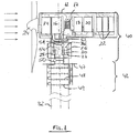
- Fig. 1 shows the first embodiment of the cooling and climate control system 100 for a wind turbine according to the present invention.
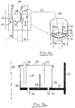
- Figs. 1a and 1b show close-up views of parts of Fig. 1 .
- the system 100 has a nacelle 12 that houses the heat generating components, including the drivetrain (or gear box) 14, the generator 16, the coolant-to-air heat exchanger 17, the hydraulics unit 18, the converter 20, and the transformer 22.
- the turbine tower 32 supports the nacelle 12 and the rotor 24.
- This system 100 is a cylindrical reservoir 26 that rests on a platform 27 inside the tower 32 just below the lower part of the nacelle 12.
- the reservoir 26 is hollow in the center and has multiple pairs of annular chambers.
- the reservoir 26 has only one pair of chambers 28 and 30 and contains only the coolant.
- the two chambers 28 and 30 are separated by a circular wall 29 in the middle.
- the height of the dividing wall 29 in the middle is lower than the inner and outer walls of the reservoir 26.
- the vertical axes of the reservoir 26 and its lid 36 are coincident with the nacelle yaw axis 38
- the reservoir lid 36 can freely rotate about its axis.
- the reservoir 26 separates the cooling system 100 into two parts: an upper cooling circuit 40 and a lower cooling circuit 42.
- the coolant flows from the first chamber 28 (the inner chamber)of the reservoir 26 to the second chamber 30 (the outer chamber) through the heat exchangers in the nacelle 12, and thus carries with it the heat from the heat generating components and the nacelle air.
- the coolant flows from the second chamber 30 (the outer chamber) of the reservoir to the first chamber 28 (the inner chamber), through the liquid-to-air heat exchanger on the tower outside and thus dissipates the heat to the ambient air.
- the two reservoir chambers 28 (inner) and 30 (outer) are connected at their respective bottoms though tubes 44 and 46 and a cooling coil 48 that wraps around the outside of the tower 32.
- the coolant flows from one chamber to the other only through the cooling coil 48.
- the cooling coil 48 is supported by one or more platforms 47 on the outside of the tower 32, The platform 47 can also act as a sun shade to minimize the solar heat load on the coil 48 during the mid-day sun.
- the cooling coil 48 is located below the reservoir 26 and thus it is always flooded with the coolant.
- the coolant flows from the chamber with higher coolant level to the other chamber through the cooling coil 48 to equilibrate the coolant levels in both chambers 28 and 30.
- the heat dissipation from the coolant to the ambient air can be augmented by fins 49 on the coil outside (the air side) or in the coil inside (the coolant side) or both. (The fins are shown in the figure as the multiple cross lines across the tube).
- the coolant flow through the coil 48 can also be augmented by an optional coolant or fluid pump 50 in the lower cooling circuit 42.
- one or more pumps 51 in the nacelle transport the coolant from the first chamber 28 of the reservoir 26 through the coolant-to-oil heat exchanger in the drivetrain 14, the generator 16, the converter 20, the coolant-to-hydraulic fluid heat exchanger 18, and the coolant-to-air heat exchanger 17, thereby picking up the heat from these components or fluids, and returning the warmer coolant to the other chamber 30.
- Flow restriction devices (not shown in the figure) control the flow rates through these components.
- the heat generated by the drivetrain 14, and that by the hydraulic system 18, is dissipated to the coolant through liquid-to-liquid heat exchangers (not shown) in the lubricating oil and the hydraulic fluid sumps, respectively.
- the heat from the air inside the nacelle is dissipated to the coolant through the liquid-to-air heat exchanger 17.
- One or more blowers help direct the cooler air exiting this heat exchanger onto the outer surfaces of the drivetrain 14, the generator 16, the converter 20, and the transformer 22, thus cooling these components from the outside.
- the coolant flows from the first chamber 28 to the second chamber 30, the heat from the heat generating components in the nacelle 12, and the air inside the nacelle 12, is removed by the upper cooling circuit 40. Due to the hydraulic force arising from the extra volume of coolant, and thus the higher coolant level in the second chamber, the coolant flows from the second chamber to the first chamber through the cooling coil 48 on the outside of the tower 32 and thus dissipates the heat to the ambient air. Air ducts and one or more blowers (not shown) in the nacelle 12 help direct the cooler air from the coolant-to-air heat exchanger to the hotspots such as the transformer 22 and return the warmer air to the heat exchanger, thus cooling the air in the nacelle 12.
- the inlet and outlet pipes 52 and 54 of the upper cooling circuit go through openings in the reservoir lid 36. Moreover, these pipes freely hang inside their respective annular reservoir chambers 28, 30. As the nacelle 12 yaws to direct the rotor blades 24 towards the wind direction, these inlet and outlet pipes freely rotate inside their respective reservoir chambers along with the reservoir lid 36.
- the hollow open space in the center of the reservoir and the corresponding open space in the platform provide the access path between the nacelle 12 and the bottom of the tower 32, for example, for the electrical lines from the nacelle 12 to the bottom of the tower 32. If the outer diameter of the reservoir 26 is smaller than the inside diameter of the tower 32, additional access paths from the tower 32 to the nacelle 12 can be created through openings in the platform in the space between the reservoir 26 and the inside of the tower 32.
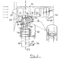
- Fig. 2 shows a second embodiment of the present invention, which is a variation of the first embodiment.
- the system 200 of Fig. 2 has an open airflow through the turbine.
- the clean ambient air enters the tower 32 and/or the nacelle 12 through one or more inlets (non-limiting examples are 56, 58, 60) where it enters respective air treatment units 62, 64, 68, flows over and cools the heat generating components (e.g., the drivetrain 14, the generator 16, the converter 20, and the transformer 22), and the warm air exits the rear top of the nacelle 12.
- the turbine can be ventilated continuously to maintain the desired air temperature inside the nacelle 12.
- the heat generated by the drivetrain 14, and the heat generated by the hydraulic components 18, is first transferred to the coolant through liquid-to-liquid heat exchangers in the lubricating oil and hydraulic fluid sumps, respectively, then transported by the coolant to the outside of the tower 32 and finally dissipated to the ambient air,
- the coolant in the upper cooling circuit 40 also picks up the heat from the generator 16, the converter 20, and the coolant-to-air heat exchanger and dissipates it to the ambient air.
- the heat carried by the lubricating oil and the hydraulic fluid is directly dissipated to the ambient air.
- Fig. 3a shows a close-up view of parts of Fig. 3 .
- Figs. 3 and 3a show the third embodiment of the cooling and climate control system for a wind turbine where the coolant, the lubricating oil, and the hydraulic fluid independently and directly dissipate the heat to the ambient air.
- the annular cylindrical reservoir 26 has a separate pair of annular fluid chambers (28a and 30a, 28b and 30b, and 28c and 30c, for the coolant, the lubricating oil and the hydraulic fluid, respectively), a flow pump (in the upper cooling circuit) (not shown) (similar to 51 in fig.
- the bottom each of the pair of chambers (28a and 30a, 28b and 30b, and 28c and 30c for the coolant, the lubricating oil and the hydraulic fluid, respectively) is connected through the respective inlet and outlet pipes (52a and 54a, 52b and 54b, and 52c and 54c, for the coolant, the lubricating oil and the hydraulic fluid, respectively) and their respective cooling coils 48a, 48b and 48c.
- the turbine is sealed (closed airflow system) and the heat from the nacelle air is dissipated to the coolant through a coolant-to-air heat exchanger.
- the fluid pumps in the upper cooling circuits, and the optional fluid pumps in the lower cooling circuits and the bypass valves are not shown in the figure for clarity.
- the reservoir lid 36 rotates freely over the reservoir 26 when the nacelle yaws.
- the inlet pipes (52a, 52b and 52c for the coolant, lubricating oil and the hydraulic fluid, respectively) and outlet pipes (54a, 54b and 54c for the coolant, lubricating oil and the hydraulic fluid, respectively) also rotate freely inside their respective fluid chambers.
- the lubricating oil and the hydraulic fluid have independent flow circuits and dissipate the heat directly to the ambient air, This helps minimize the thermal inefficiencies associated with the use of coolant-to-oil and coolant-to-hydraulic fluid heat exchangers.
- the height of the circular wall separating the two chambers of a particular pair of the reservoir chambers is such that the wall permits overflow of the fluid from one chamber to the other in case the fluid level in one chamber becomes exceedingly high for any reason. This can ensure that there is always a minimum volume of the fluid in either of a particular pair of chambers.
- the heat dissipation from a particular fluid to the ambient air can be augmented by fins on the coil outside (the air side) or in the coil inside (the liquid side) or both.
- a fluid pump can also be used in any of the lower cooling circuits to increase the fluid velocity of that circuit, and thus augmenting the heat dissipation from that fluid to the ambient air.
- thermostatically controlled flow bypasses can also be used in the upper or lower flow circuits.
- the fluid chambers, the fluid volumes, the pumps, the bypass valves, and the coils that dissipate the heat from the fluids to the ambient air can be sized appropriately to meet the design needs of the particular turbine,
Landscapes
- Engineering & Computer Science (AREA)
- Life Sciences & Earth Sciences (AREA)
- Sustainable Development (AREA)
- Sustainable Energy (AREA)
- Chemical & Material Sciences (AREA)
- Combustion & Propulsion (AREA)
- Mechanical Engineering (AREA)
- General Engineering & Computer Science (AREA)
- Wind Motors (AREA)
Claims (12)
- System zum Kühlen der Luft innerhalb einer Gondel einer Windenergieanlage, umfassend einen oberen Kühlkreislauf (40) mit einem unterhalb der Gondel vorgesehenen Reservoir (26), wobei das Reservoir mindestens ein Paar Ringkammern (28, 28a, 30, 30a) und einen Deckel (36) aufweist, der sich frei um seine eigene Achse und um die Gondelgierachse (38) dreht, wobei in der Gondel (12) Kühlmittel aus einer ersten Ringkammer (28, 28a) durch einen Wärmetauscher (17) in eine zweite Ringkammer (30, 30a) strömt und dadurch Wärme aus der Gondel (12) in die zweite Ringkammer (30, 30a) trägt, und einen unteren Kühlkreislauf (42), dadurch gekennzeichnet, dass der untere Kühlkreislauf eine Kühlspule (48, 48a) umfasst, die die erste Ringkammer (28, 28a) mit der zweiten Ringkammer (30, 30a) verbindet und gegenüber einer Außenseite der Windenergieanlage freiliegt, wobei das Kühlmittel aus der zweiten Ringkammer (30a) durch die Spule (48, 48a) in die erste Ringkammer (28a) strömt und dadurch die Wärme an die Umgebungsluft abgibt.
- System nach Anspruch 1, dadurch gekennzeichnet, dass das Reservoir (26) zylindrisch ist und durch eine Plattform (27) innerhalb eines Turms (32) der Windenergieanlage getragen wird.
- System nach Anspruch 2, dadurch gekennzeichnet, dass korrespondierende offene Räume in dem Reservoir (26) und der Plattform (27) einen Zugangsweg zwischen der Gondel (12) und dem Turm (32) bereitstellen.
- System nach Anspruch 1, dadurch gekennzeichnet, dass die Spule (48, 48a) um die Außenseite eines Turms (32) der Windenergieanlage gewickelt ist.
- System nach Anspruch 1, dadurch gekennzeichnet, dass die Spule (48, 48a) durch eine oder mehrere Plattformen (47) an der Außenseite des Turms (32) gestützt wird.
- System nach Anspruch 1, dadurch gekennzeichnet, dass innerhalb und außerhalb der Spule (48, 48a) einige Rippen (49) angeordnet sind, um die Abgabe der Wärme aus dem Kühlmittel an die Umgebungsluft zu unterstützen.
- System nach Anspruch 1, dadurch gekennzeichnet, dass, wenn ein Kühlmittelstand in einer Kammer (28, 28a oder 30, 30a) höher ist als in der anderen (28a oder 30a), das Kühlmittel aus der einen Kammer durch die Spule (48, 48a) in die andere Kammer strömt, um die Kühlmittelstände in beiden Kammern (28, 28a; 30, 30a)) äquilibrieren.
- System nach Anspruch 1, dadurch gekennzeichnet, dass der untere Kühlkreislauf (42) ferner eine Kühlmittelpumpe (50) umfasst, um den Kühlmittelfluss durch die Spule (48, 48a) zu verstärken.
- System nach Anspruch 1, dadurch gekennzeichnet, dass der obere Kühlkreislauf (40) ferner mindestens eine Pumpe (51) umfasst, um die Beförderung des Kühlmittels aus der ersten Ringkammer durch die Gondel (12) in die zweite Ringkammer (30, 30a) zu unterstützen und dadurch Wärme aus der Gondel (12) zu gewinnen und das wärmere Kühlmittel in die zweite Ringkammer (30, 30a) zurückzuführen.
- System nach Anspruch 1, dadurch gekennzeichnet, dass jede Ringkammer (28, 28a; 30, 30a) eine kreisförmige Wand (29, 29a) zum Trennen von Kühlmittel darin aufweist, und wobei die Höhe der kreisförmigen Wand (29, 29a) in einer gegebenen Kammer geringer ist als die Höhe der Innen- und Außenwände der Kammer.
- System nach Anspruch 1, dadurch gekennzeichnet, dass es eine Vielzahl von Einlässen (56, 58, 60) und korrespondierende Luftbehandlungseinheiten (62, 64, 68) umfasst, die an einem Boden eines Turms (32) der Windenergieanlage und an der Gondel (12) vorgesehen sind und dadurch einen offenen Luftstrom durch die Windenergieanlage bereitstellen, so dass saubere Umgebungsluft durch einen der Einlässe in den Turm (32) eintritt und abkühlt und dann aus der Gondel (12) austritt.
- System nach einem der Ansprüche 1 bis 11, dadurch gekennzeichnet, dass
es für das Kühlmittel, für Schmieröl und für Hydraulikfluid jeweils unabhängige Strömungskreisläufe umfasst,
das Reservoir (26) für das Kühlmittel, für Schmieröl und für Hydraulikfluid jeweils Paare von Fluidringkammern (28a, 30a; 28b, 30b; 28c, 30c) aufweist, wobei die Paare voneinander getrennt sind und jedes Paar Fluidkammern (28a, 30a; 28b, 30b; 28c, 30c) eine erste Ringkammer (28a, 28b, 28c), aus der das Kühlmittel, das Schmieröl und das Hydraulikfluid in die Gondel (12) strömen, und eine zweite Ringkammer (30a, 30b, 30c) umfasst,
das Kühlmittel, das Schmieröl und das Hydraulikfluid, die in die zweiten Ringkammern (30a, 30b, 30c) strömen, Wärme aus der Gondel (12) in die jeweilige zweite Ringkammer (30a, 30b, 30c) tragen,
der untere Kühlkreislauf eine Vielzahl von unabhängigen Kühlspulen (48a, 48b, 48c) umfasst, die zumindest teilweise gegenüber der Außenseite eines Turms (32) der Windenergieanlage freiliegen, wobei jede Spule (48a, 48b, 48c) die zweite Ringkammer (30a, 30b, 30c) mit der ersten Ringkammer (28a, 28b, 28c) eines Paares Ringkammern verbindet und wobei jede Spule jeweils für das Kühlmittel, das Schmieröl bzw. das Hydraulikfluid bestimmt ist, so dass Wärme aus der Gondel (12) an das Kühlmittel, das Schmieröl und das Hydraulikfluid und dann an die Umgebungsluft abgegeben wird und das Kühlmittel, das Schmieröl und die Hydraulikflüssigkeit durch die jeweiligen Spulen (48a, 48b, 48c) in die jeweiligen ersten Ringkammern (28a, 28b, 28c) strömen.
Applications Claiming Priority (1)
| Application Number | Priority Date | Filing Date | Title |
|---|---|---|---|
| US13/238,042 US8747060B2 (en) | 2011-09-21 | 2011-09-21 | Cooling and climate control system and method for a wind turbine |
Publications (3)
| Publication Number | Publication Date |
|---|---|
| EP2573389A2 EP2573389A2 (de) | 2013-03-27 |
| EP2573389A3 EP2573389A3 (de) | 2017-12-13 |
| EP2573389B1 true EP2573389B1 (de) | 2019-03-06 |
Family
ID=47008235
Family Applications (1)
| Application Number | Title | Priority Date | Filing Date |
|---|---|---|---|
| EP12006625.3A Not-in-force EP2573389B1 (de) | 2011-09-21 | 2012-09-21 | Kühl- und Klimaregelsystem und -verfahren für eine Windturbine |
Country Status (3)
| Country | Link |
|---|---|
| US (1) | US8747060B2 (de) |
| EP (1) | EP2573389B1 (de) |
| DK (1) | DK2573389T3 (de) |
Families Citing this family (14)
| Publication number | Priority date | Publication date | Assignee | Title |
|---|---|---|---|---|
| EP2402593A4 (de) * | 2009-02-27 | 2013-04-10 | Mitsubishi Heavy Ind Ltd | Windbetriebener generator |
| US20130028729A1 (en) * | 2011-07-28 | 2013-01-31 | Jones Jack A | Power generation systems and methods |
| JP6165492B2 (ja) * | 2013-04-15 | 2017-07-19 | 株式会社日立製作所 | 風力発電設備 |
| CN103352806B (zh) * | 2013-06-17 | 2015-12-09 | 沈阳华创风能有限公司 | 轮毂冷却控制方法及其装置 |
| JP2015010579A (ja) * | 2013-07-01 | 2015-01-19 | 株式会社安川電機 | 風力発電システム |
| DE102016111332B3 (de) * | 2016-06-21 | 2017-06-29 | Aerodyn Engineering Gmbh | Modular aufgebaute Windenergieanlage |
| CN108869204B (zh) * | 2018-05-22 | 2019-09-20 | 新疆金风科技股份有限公司 | 散热系统、风力发电机组及散热支撑平台 |
| CN113775489B (zh) * | 2020-06-09 | 2024-09-20 | 金风科技股份有限公司 | 冷却系统及风力发电机组 |
| CN112431730B (zh) * | 2020-11-23 | 2022-08-26 | 上海齐耀动力技术有限公司 | 一种海上水电风冷系统 |
| EP4266556A1 (de) * | 2022-04-22 | 2023-10-25 | Siemens Gamesa Renewable Energy A/S | Kühlkreislauf für einen elektrischen generator |
| CN117365880A (zh) * | 2022-06-30 | 2024-01-09 | 金风科技股份有限公司 | 冷却系统以及海上风力发电机组 |
| CN121039393A (zh) * | 2023-05-23 | 2025-11-28 | 维斯塔斯风力系统有限公司 | 与冷却风力涡轮机有关的改进 |
| JP7849063B2 (ja) * | 2024-08-27 | 2026-04-21 | 王明正 | 放熱フィン不要の封鎖型冷却オイル浸漬式冷却システム |
| CN121066793A (zh) * | 2025-10-22 | 2025-12-05 | 河南云风能源科技有限公司 | 一种风力发电机组的冷却系统及风力发电机组 |
Family Cites Families (13)
| Publication number | Priority date | Publication date | Assignee | Title |
|---|---|---|---|---|
| DE19859628C1 (de) | 1998-12-23 | 2000-03-23 | Aerodyn Eng Gmbh | Vorrichtung zur Vermeidung des Eindringens von korrosiv wirkenden Salzpartikeln |
| EP1185790B1 (de) | 1999-05-07 | 2004-10-27 | NEG Micon A/S | Offshore windturbine mit flüssigkeitskühlung |
| DE10016913A1 (de) * | 2000-04-05 | 2001-10-18 | Aerodyn Eng Gmbh | Offshore-Windenergieanlage mit einem Wärmetauschersystem |
| DE10324228B4 (de) | 2003-05-28 | 2006-02-16 | Rittal Gmbh & Co. Kg | Kühlvorrichtung für eine Offshore-Windenergieanlage |
| US7168251B1 (en) * | 2005-12-14 | 2007-01-30 | General Electric Company | Wind energy turbine |
| EP2126351B1 (de) | 2007-01-31 | 2014-05-07 | Vestas Wind Systems A/S | Windenergiewandler mit entfeuchter |
| GR1006291B (el) * | 2007-02-22 | 2009-03-09 | Διονυσιος Χαραλαμπους Χοϊδας | Ψυκτικη διαταξη ανεμογεννητριας |
| ES2330491B1 (es) * | 2007-05-25 | 2010-09-14 | GAMESA INNOVATION & TECHNOLOGY, S.L. | Sistema de climatizacion para aerogeneradores. |
| US8047774B2 (en) | 2008-09-11 | 2011-11-01 | General Electric Company | System for heating and cooling wind turbine components |
| CN101392729B (zh) * | 2008-10-29 | 2010-12-08 | 南京航空航天大学 | 采用太阳能喷射式冷却的风力发电机 |
| EP2376778B1 (de) | 2008-12-17 | 2017-02-08 | XEMC Darwind BV | Einen kühlkreislauf umfassende windturbine |
| US7837126B2 (en) | 2009-09-25 | 2010-11-23 | General Electric Company | Method and system for cooling a wind turbine structure |
| US9127648B2 (en) * | 2011-04-19 | 2015-09-08 | Gamesa Innovation & Technology, S.L. | System to cool the nacelle and the heat generating components of an offshore wind turbine |
-
2011
- 2011-09-21 US US13/238,042 patent/US8747060B2/en active Active
-
2012
- 2012-09-21 DK DK12006625.3T patent/DK2573389T3/da active
- 2012-09-21 EP EP12006625.3A patent/EP2573389B1/de not_active Not-in-force
Non-Patent Citations (1)
| Title |
|---|
| None * |
Also Published As
| Publication number | Publication date |
|---|---|
| EP2573389A2 (de) | 2013-03-27 |
| EP2573389A3 (de) | 2017-12-13 |
| US20130071236A1 (en) | 2013-03-21 |
| US8747060B2 (en) | 2014-06-10 |
| DK2573389T3 (da) | 2019-06-11 |
Similar Documents
| Publication | Publication Date | Title |
|---|---|---|
| EP2573389B1 (de) | Kühl- und Klimaregelsystem und -verfahren für eine Windturbine | |
| EP2527650B1 (de) | System zum Kühlen der Gondel und der wärmeerzeugenden Komponenten einer Offshore-Windturbine | |
| EP2530312B1 (de) | Kühl- und Klimaregelsystem und -verfahren für eine Offshore-Windturbine | |
| US8992171B2 (en) | Energy efficient climate control system for an offshore wind turbine | |
| US9091249B2 (en) | Integrated cooling and climate control system for an offshore wind turbine | |
| CN101384818B (zh) | 用于风轮机的热管理系统 | |
| CN103424019B (zh) | 自然循环型冷却装置 | |
| US20080307817A1 (en) | System for integrated thermal management and method for the same | |
| KR20130050274A (ko) | 재생 에너지형 발전 장치 | |
| CN102098902A (zh) | 散热设备、通信设备的散热方法及通信设备 | |
| EP4010592B1 (de) | Windturbinenkühlsystem | |
| EP4440268A1 (de) | Datenzentrum | |
| US12247551B2 (en) | Rooftop containerized HVAC module for wind turbine generator | |
| CN115667709B (zh) | 带有液桥的多虹吸被动冷却系统 | |
| CN102612303B (zh) | 无线通讯模块的散热系统和温控单元 | |
| JP6230424B2 (ja) | 風力発電装置 | |
| JP2013130332A (ja) | 気泡駆動冷却装置 | |
| EP3805559A1 (de) | Windturbinenkühlsystem | |
| CN219691675U (zh) | 风电塔筒底部平台散热装置及风电塔 | |
| CN219412816U (zh) | 一种内嵌风道风电机舱散热装置 |
Legal Events
| Date | Code | Title | Description |
|---|---|---|---|
| PUAI | Public reference made under article 153(3) epc to a published international application that has entered the european phase |
Free format text: ORIGINAL CODE: 0009012 |
|
| AK | Designated contracting states |
Kind code of ref document: A2 Designated state(s): AL AT BE BG CH CY CZ DE DK EE ES FI FR GB GR HR HU IE IS IT LI LT LU LV MC MK MT NL NO PL PT RO RS SE SI SK SM TR |
|
| AX | Request for extension of the european patent |
Extension state: BA ME |
|
| RAP1 | Party data changed (applicant data changed or rights of an application transferred) |
Owner name: ADWEN OFFSHORE, S.L. |
|
| PUAL | Search report despatched |
Free format text: ORIGINAL CODE: 0009013 |
|
| AK | Designated contracting states |
Kind code of ref document: A3 Designated state(s): AL AT BE BG CH CY CZ DE DK EE ES FI FR GB GR HR HU IE IS IT LI LT LU LV MC MK MT NL NO PL PT RO RS SE SI SK SM TR |
|
| AX | Request for extension of the european patent |
Extension state: BA ME |
|
| RIC1 | Information provided on ipc code assigned before grant |
Ipc: F03D 11/00 00000000AFI20171107BHEP |
|
| STAA | Information on the status of an ep patent application or granted ep patent |
Free format text: STATUS: REQUEST FOR EXAMINATION WAS MADE |
|
| REG | Reference to a national code |
Ref country code: DE Ref legal event code: R079 Ref document number: 602012057345 Country of ref document: DE Free format text: PREVIOUS MAIN CLASS: F03D0011000000 Ipc: F03D0080800000 |
|
| 17P | Request for examination filed |
Effective date: 20180612 |
|
| RBV | Designated contracting states (corrected) |
Designated state(s): AL AT BE BG CH CY CZ DE DK EE ES FI FR GB GR HR HU IE IS IT LI LT LU LV MC MK MT NL NO PL PT RO RS SE SI SK SM TR |
|
| RIC1 | Information provided on ipc code assigned before grant |
Ipc: F03D 80/80 20160101AFI20180717BHEP |
|
| GRAP | Despatch of communication of intention to grant a patent |
Free format text: ORIGINAL CODE: EPIDOSNIGR1 |
|
| STAA | Information on the status of an ep patent application or granted ep patent |
Free format text: STATUS: GRANT OF PATENT IS INTENDED |
|
| INTG | Intention to grant announced |
Effective date: 20180910 |
|
| GRAS | Grant fee paid |
Free format text: ORIGINAL CODE: EPIDOSNIGR3 |
|
| GRAA | (expected) grant |
Free format text: ORIGINAL CODE: 0009210 |
|
| STAA | Information on the status of an ep patent application or granted ep patent |
Free format text: STATUS: THE PATENT HAS BEEN GRANTED |
|
| AK | Designated contracting states |
Kind code of ref document: B1 Designated state(s): AL AT BE BG CH CY CZ DE DK EE ES FI FR GB GR HR HU IE IS IT LI LT LU LV MC MK MT NL NO PL PT RO RS SE SI SK SM TR |
|
| REG | Reference to a national code |
Ref country code: GB Ref legal event code: FG4D |
|
| REG | Reference to a national code |
Ref country code: CH Ref legal event code: EP Ref country code: AT Ref legal event code: REF Ref document number: 1104894 Country of ref document: AT Kind code of ref document: T Effective date: 20190315 |
|
| REG | Reference to a national code |
Ref country code: DE Ref legal event code: R096 Ref document number: 602012057345 Country of ref document: DE |
|
| REG | Reference to a national code |
Ref country code: IE Ref legal event code: FG4D |
|
| REG | Reference to a national code |
Ref country code: DK Ref legal event code: T3 Effective date: 20190607 |
|
| REG | Reference to a national code |
Ref country code: NL Ref legal event code: MP Effective date: 20190306 |
|
| REG | Reference to a national code |
Ref country code: LT Ref legal event code: MG4D |
|
| PG25 | Lapsed in a contracting state [announced via postgrant information from national office to epo] |
Ref country code: FI Free format text: LAPSE BECAUSE OF FAILURE TO SUBMIT A TRANSLATION OF THE DESCRIPTION OR TO PAY THE FEE WITHIN THE PRESCRIBED TIME-LIMIT Effective date: 20190306 Ref country code: NO Free format text: LAPSE BECAUSE OF FAILURE TO SUBMIT A TRANSLATION OF THE DESCRIPTION OR TO PAY THE FEE WITHIN THE PRESCRIBED TIME-LIMIT Effective date: 20190606 Ref country code: LT Free format text: LAPSE BECAUSE OF FAILURE TO SUBMIT A TRANSLATION OF THE DESCRIPTION OR TO PAY THE FEE WITHIN THE PRESCRIBED TIME-LIMIT Effective date: 20190306 Ref country code: SE Free format text: LAPSE BECAUSE OF FAILURE TO SUBMIT A TRANSLATION OF THE DESCRIPTION OR TO PAY THE FEE WITHIN THE PRESCRIBED TIME-LIMIT Effective date: 20190306 |
|
| PG25 | Lapsed in a contracting state [announced via postgrant information from national office to epo] |
Ref country code: LV Free format text: LAPSE BECAUSE OF FAILURE TO SUBMIT A TRANSLATION OF THE DESCRIPTION OR TO PAY THE FEE WITHIN THE PRESCRIBED TIME-LIMIT Effective date: 20190306 Ref country code: NL Free format text: LAPSE BECAUSE OF FAILURE TO SUBMIT A TRANSLATION OF THE DESCRIPTION OR TO PAY THE FEE WITHIN THE PRESCRIBED TIME-LIMIT Effective date: 20190306 Ref country code: RS Free format text: LAPSE BECAUSE OF FAILURE TO SUBMIT A TRANSLATION OF THE DESCRIPTION OR TO PAY THE FEE WITHIN THE PRESCRIBED TIME-LIMIT Effective date: 20190306 Ref country code: BG Free format text: LAPSE BECAUSE OF FAILURE TO SUBMIT A TRANSLATION OF THE DESCRIPTION OR TO PAY THE FEE WITHIN THE PRESCRIBED TIME-LIMIT Effective date: 20190606 Ref country code: GR Free format text: LAPSE BECAUSE OF FAILURE TO SUBMIT A TRANSLATION OF THE DESCRIPTION OR TO PAY THE FEE WITHIN THE PRESCRIBED TIME-LIMIT Effective date: 20190607 Ref country code: HR Free format text: LAPSE BECAUSE OF FAILURE TO SUBMIT A TRANSLATION OF THE DESCRIPTION OR TO PAY THE FEE WITHIN THE PRESCRIBED TIME-LIMIT Effective date: 20190306 |
|
| REG | Reference to a national code |
Ref country code: AT Ref legal event code: MK05 Ref document number: 1104894 Country of ref document: AT Kind code of ref document: T Effective date: 20190306 |
|
| PG25 | Lapsed in a contracting state [announced via postgrant information from national office to epo] |
Ref country code: EE Free format text: LAPSE BECAUSE OF FAILURE TO SUBMIT A TRANSLATION OF THE DESCRIPTION OR TO PAY THE FEE WITHIN THE PRESCRIBED TIME-LIMIT Effective date: 20190306 Ref country code: AL Free format text: LAPSE BECAUSE OF FAILURE TO SUBMIT A TRANSLATION OF THE DESCRIPTION OR TO PAY THE FEE WITHIN THE PRESCRIBED TIME-LIMIT Effective date: 20190306 Ref country code: PT Free format text: LAPSE BECAUSE OF FAILURE TO SUBMIT A TRANSLATION OF THE DESCRIPTION OR TO PAY THE FEE WITHIN THE PRESCRIBED TIME-LIMIT Effective date: 20190706 Ref country code: SK Free format text: LAPSE BECAUSE OF FAILURE TO SUBMIT A TRANSLATION OF THE DESCRIPTION OR TO PAY THE FEE WITHIN THE PRESCRIBED TIME-LIMIT Effective date: 20190306 Ref country code: IT Free format text: LAPSE BECAUSE OF FAILURE TO SUBMIT A TRANSLATION OF THE DESCRIPTION OR TO PAY THE FEE WITHIN THE PRESCRIBED TIME-LIMIT Effective date: 20190306 Ref country code: CZ Free format text: LAPSE BECAUSE OF FAILURE TO SUBMIT A TRANSLATION OF THE DESCRIPTION OR TO PAY THE FEE WITHIN THE PRESCRIBED TIME-LIMIT Effective date: 20190306 Ref country code: ES Free format text: LAPSE BECAUSE OF FAILURE TO SUBMIT A TRANSLATION OF THE DESCRIPTION OR TO PAY THE FEE WITHIN THE PRESCRIBED TIME-LIMIT Effective date: 20190306 Ref country code: RO Free format text: LAPSE BECAUSE OF FAILURE TO SUBMIT A TRANSLATION OF THE DESCRIPTION OR TO PAY THE FEE WITHIN THE PRESCRIBED TIME-LIMIT Effective date: 20190306 |
|
| PG25 | Lapsed in a contracting state [announced via postgrant information from national office to epo] |
Ref country code: SM Free format text: LAPSE BECAUSE OF FAILURE TO SUBMIT A TRANSLATION OF THE DESCRIPTION OR TO PAY THE FEE WITHIN THE PRESCRIBED TIME-LIMIT Effective date: 20190306 Ref country code: PL Free format text: LAPSE BECAUSE OF FAILURE TO SUBMIT A TRANSLATION OF THE DESCRIPTION OR TO PAY THE FEE WITHIN THE PRESCRIBED TIME-LIMIT Effective date: 20190306 |
|
| REG | Reference to a national code |
Ref country code: DE Ref legal event code: R097 Ref document number: 602012057345 Country of ref document: DE |
|
| PG25 | Lapsed in a contracting state [announced via postgrant information from national office to epo] |
Ref country code: IS Free format text: LAPSE BECAUSE OF FAILURE TO SUBMIT A TRANSLATION OF THE DESCRIPTION OR TO PAY THE FEE WITHIN THE PRESCRIBED TIME-LIMIT Effective date: 20190706 Ref country code: AT Free format text: LAPSE BECAUSE OF FAILURE TO SUBMIT A TRANSLATION OF THE DESCRIPTION OR TO PAY THE FEE WITHIN THE PRESCRIBED TIME-LIMIT Effective date: 20190306 |
|
| PLBE | No opposition filed within time limit |
Free format text: ORIGINAL CODE: 0009261 |
|
| STAA | Information on the status of an ep patent application or granted ep patent |
Free format text: STATUS: NO OPPOSITION FILED WITHIN TIME LIMIT |
|
| 26N | No opposition filed |
Effective date: 20191209 |
|
| PG25 | Lapsed in a contracting state [announced via postgrant information from national office to epo] |
Ref country code: SI Free format text: LAPSE BECAUSE OF FAILURE TO SUBMIT A TRANSLATION OF THE DESCRIPTION OR TO PAY THE FEE WITHIN THE PRESCRIBED TIME-LIMIT Effective date: 20190306 |
|
| PG25 | Lapsed in a contracting state [announced via postgrant information from national office to epo] |
Ref country code: TR Free format text: LAPSE BECAUSE OF FAILURE TO SUBMIT A TRANSLATION OF THE DESCRIPTION OR TO PAY THE FEE WITHIN THE PRESCRIBED TIME-LIMIT Effective date: 20190306 |
|
| PG25 | Lapsed in a contracting state [announced via postgrant information from national office to epo] |
Ref country code: MC Free format text: LAPSE BECAUSE OF FAILURE TO SUBMIT A TRANSLATION OF THE DESCRIPTION OR TO PAY THE FEE WITHIN THE PRESCRIBED TIME-LIMIT Effective date: 20190306 |
|
| REG | Reference to a national code |
Ref country code: CH Ref legal event code: PL |
|
| PG25 | Lapsed in a contracting state [announced via postgrant information from national office to epo] |
Ref country code: CH Free format text: LAPSE BECAUSE OF NON-PAYMENT OF DUE FEES Effective date: 20190930 Ref country code: LI Free format text: LAPSE BECAUSE OF NON-PAYMENT OF DUE FEES Effective date: 20190930 Ref country code: LU Free format text: LAPSE BECAUSE OF NON-PAYMENT OF DUE FEES Effective date: 20190921 Ref country code: IE Free format text: LAPSE BECAUSE OF NON-PAYMENT OF DUE FEES Effective date: 20190921 |
|
| REG | Reference to a national code |
Ref country code: BE Ref legal event code: MM Effective date: 20190930 |
|
| PG25 | Lapsed in a contracting state [announced via postgrant information from national office to epo] |
Ref country code: BE Free format text: LAPSE BECAUSE OF NON-PAYMENT OF DUE FEES Effective date: 20190930 |
|
| PG25 | Lapsed in a contracting state [announced via postgrant information from national office to epo] |
Ref country code: FR Free format text: LAPSE BECAUSE OF NON-PAYMENT OF DUE FEES Effective date: 20190930 |
|
| PG25 | Lapsed in a contracting state [announced via postgrant information from national office to epo] |
Ref country code: CY Free format text: LAPSE BECAUSE OF FAILURE TO SUBMIT A TRANSLATION OF THE DESCRIPTION OR TO PAY THE FEE WITHIN THE PRESCRIBED TIME-LIMIT Effective date: 20190306 |
|
| PG25 | Lapsed in a contracting state [announced via postgrant information from national office to epo] |
Ref country code: HU Free format text: LAPSE BECAUSE OF FAILURE TO SUBMIT A TRANSLATION OF THE DESCRIPTION OR TO PAY THE FEE WITHIN THE PRESCRIBED TIME-LIMIT; INVALID AB INITIO Effective date: 20120921 Ref country code: MT Free format text: LAPSE BECAUSE OF FAILURE TO SUBMIT A TRANSLATION OF THE DESCRIPTION OR TO PAY THE FEE WITHIN THE PRESCRIBED TIME-LIMIT Effective date: 20190306 |
|
| PGFP | Annual fee paid to national office [announced via postgrant information from national office to epo] |
Ref country code: DK Payment date: 20210920 Year of fee payment: 10 |
|
| PGFP | Annual fee paid to national office [announced via postgrant information from national office to epo] |
Ref country code: GB Payment date: 20211022 Year of fee payment: 10 Ref country code: DE Payment date: 20211020 Year of fee payment: 10 |
|
| PG25 | Lapsed in a contracting state [announced via postgrant information from national office to epo] |
Ref country code: MK Free format text: LAPSE BECAUSE OF FAILURE TO SUBMIT A TRANSLATION OF THE DESCRIPTION OR TO PAY THE FEE WITHIN THE PRESCRIBED TIME-LIMIT Effective date: 20190306 |
|
| REG | Reference to a national code |
Ref country code: DE Ref legal event code: R082 Ref document number: 602012057345 Country of ref document: DE Representative=s name: SAUTHOFF, KARSTEN, DIPL.-ING. UNIV., DE |
|
| REG | Reference to a national code |
Ref country code: DE Ref legal event code: R119 Ref document number: 602012057345 Country of ref document: DE |
|
| REG | Reference to a national code |
Ref country code: DK Ref legal event code: EBP Effective date: 20220930 |
|
| GBPC | Gb: european patent ceased through non-payment of renewal fee |
Effective date: 20220921 |
|
| PG25 | Lapsed in a contracting state [announced via postgrant information from national office to epo] |
Ref country code: DE Free format text: LAPSE BECAUSE OF NON-PAYMENT OF DUE FEES Effective date: 20230401 |
|
| PG25 | Lapsed in a contracting state [announced via postgrant information from national office to epo] |
Ref country code: GB Free format text: LAPSE BECAUSE OF NON-PAYMENT OF DUE FEES Effective date: 20220921 Ref country code: DK Free format text: LAPSE BECAUSE OF NON-PAYMENT OF DUE FEES Effective date: 20220930 |