EP2573401A2 - Pompe pour liquide de refroidissement - Google Patents
Pompe pour liquide de refroidissement Download PDFInfo
- Publication number
- EP2573401A2 EP2573401A2 EP12185115A EP12185115A EP2573401A2 EP 2573401 A2 EP2573401 A2 EP 2573401A2 EP 12185115 A EP12185115 A EP 12185115A EP 12185115 A EP12185115 A EP 12185115A EP 2573401 A2 EP2573401 A2 EP 2573401A2
- Authority
- EP
- European Patent Office
- Prior art keywords
- shaft
- adjacent
- inner shell
- shell
- seat
- Prior art date
- Legal status (The legal status is an assumption and is not a legal conclusion. Google has not performed a legal analysis and makes no representation as to the accuracy of the status listed.)
- Withdrawn
Links
- 238000001816 cooling Methods 0.000 title claims abstract description 17
- 239000007788 liquid Substances 0.000 title 1
- XLYOFNOQVPJJNP-UHFFFAOYSA-N water Substances O XLYOFNOQVPJJNP-UHFFFAOYSA-N 0.000 abstract description 16
- 238000005299 abrasion Methods 0.000 abstract description 6
- 230000000694 effects Effects 0.000 abstract description 6
- 230000017525 heat dissipation Effects 0.000 description 3
- 230000008595 infiltration Effects 0.000 description 1
- 238000001764 infiltration Methods 0.000 description 1
- 239000000314 lubricant Substances 0.000 description 1
- 238000007789 sealing Methods 0.000 description 1
Images



Classifications
-
- F—MECHANICAL ENGINEERING; LIGHTING; HEATING; WEAPONS; BLASTING
- F04—POSITIVE - DISPLACEMENT MACHINES FOR LIQUIDS; PUMPS FOR LIQUIDS OR ELASTIC FLUIDS
- F04D—NON-POSITIVE-DISPLACEMENT PUMPS
- F04D13/00—Pumping installations or systems
- F04D13/02—Units comprising pumps and their driving means
- F04D13/06—Units comprising pumps and their driving means the pump being electrically driven
-
- F—MECHANICAL ENGINEERING; LIGHTING; HEATING; WEAPONS; BLASTING
- F04—POSITIVE - DISPLACEMENT MACHINES FOR LIQUIDS; PUMPS FOR LIQUIDS OR ELASTIC FLUIDS
- F04D—NON-POSITIVE-DISPLACEMENT PUMPS
- F04D29/00—Details, component parts, or accessories
- F04D29/40—Casings; Connections of working fluid
- F04D29/42—Casings; Connections of working fluid for radial or helico-centrifugal pumps
- F04D29/426—Casings; Connections of working fluid for radial or helico-centrifugal pumps especially adapted for liquid pumps
- F04D29/4273—Casings; Connections of working fluid for radial or helico-centrifugal pumps especially adapted for liquid pumps suction eyes
-
- F—MECHANICAL ENGINEERING; LIGHTING; HEATING; WEAPONS; BLASTING
- F04—POSITIVE - DISPLACEMENT MACHINES FOR LIQUIDS; PUMPS FOR LIQUIDS OR ELASTIC FLUIDS
- F04D—NON-POSITIVE-DISPLACEMENT PUMPS
- F04D29/00—Details, component parts, or accessories
- F04D29/58—Cooling; Heating; Diminishing heat transfer
- F04D29/5806—Cooling the drive system
Definitions
- the present invention relates to a liquid-cooling pump, and more particularly to a liquid-cooling pump to reduce an abrasion and having good heat dissipation.
- a conventional pump has a shell 90.
- a chamber 91 is defined in the shell 90.
- the shell 90 has an inlet 92 and an outlet 93 which are both in communication with the chamber 91.
- a shaft 94 is mounted in the shell 90 and extends into the chamber 91.
- An impeller 95 is mounted on the shaft 94 at the chamber 91 and is controlled by a motor 97.
- a shaft seal 96 and a waterproof washer are mounted on the shaft 94 and abut against the chamber 91.
- the impeller 95 When the motor 97 is driving, the impeller 95 is rotated by the shaft 94, and water flows through the impeller 95 and generates a centrifugal vortex.
- Water in the chamber 91 generates a hydraulic pressure by the centrifugal vortex to push water to flow to a destination.
- the shaft seal 96 While the hydraulic pressure is high, the shaft seal 96 is pressed to generate a gap, and then water is infiltrated through the gap.
- the shaft seal 96 is tightly mounted on the shaft 94 to avoid the gap between the shaft seal 96 and the shaft 94.
- the seal tightness between the shaft seal 96 and the shaft 94 is enhanced to increase a waterproof effect of the pump.
- the shaft seal 96 tightly mounted on the shaft 94 causes an abrasion between the shaft seal 96 and the shaft 94.
- the hydraulic pressure is high and presses the shaft seal 96, and then a gap between the shaft 94 and the shaft seal 96 is formed to cause water infiltration, damage the pump, and reduce the waterproof effect.
- the present invention tends to provide a liquid-cooling pump to mitigate or obviate the aforementioned problems.
- the main objective of the invention is to provide a liquid-cooling pump to reduce an abrasion and increase the waterproof effect.
- the liquid-cooling pump has a casing device, a driving device and an impeller.
- the casing device has an outer shell, an inner shell and a channel.
- the outer shell has an inlet, an outlet and an outer guiding cap.
- the inlet and the outlet are mounted respectively at two sides of the outer shell.
- the outer guiding cap is adjacent to the outlet.
- the inner shell is mounted in the outer shell and has an inner guiding cap, a first end, a second end, an assembling chamber and an oil chamber.
- the inner guiding cap is corresponding to the outer guiding cap.
- the first end is defined in the inner shell and is adjacent to the inlet of the outer shell.
- the second end is defined in the inner guiding cap and is adjacent to the outlet of the outer shell.
- the assembling chamber is defined in the inner shell.
- the oil chamber is defined in the inner shell and is adjacent to the second end of the inner shell.
- the channel is defined between the outer shell and the inner shell.
- the driving device is mounted in the inner shell and has a rotor and a stator mounted in the assembling chamber of the inner shell, and has a shaft, an oil seal and a shaft seal.
- the shaft is connected with the rotor and extends out of the second end of the inner shell.
- the oil seal is mounted on the shaft adjacent to the second end of the inner shell.
- the shaft seal is mounted on the shaft and adjacent to the second end of the inner shell.
- the impeller is mounted on the shaft of the driving device and is located at the channel, and the impeller is adjacent to the second end of the inner shell and the outlet of the outer shell.
- the oil seal and the shaft seal are adjacent to the second end of the inner shell that is under a negative pressure condition.
- water flowing through the channel does not directly impact the oil seal and the shaft seal, and the hydraulic pressure applied to the oil seal and the shaft seal are low.
- a tightness degree between the shaft and the shaft seal is reduced and can prevent an abrasion between the shaft and the shaft seal and increase the waterproof effect.
- water flowing through the channel can absorb the heat generated by the driving device to provide good heat dissipation.
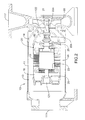
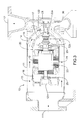
- a liquid-cooling pump in accordance with the present invention comprises a casing device 10, a driving device 20 and an impeller 30.
- the casing device 10 has an outer shell 11, an inner shell 12 and a channel 13.
- the outer shell 11 has an inlet 111 and an outlet 112 formed respectively at two sides of the outer shell 11 and has an outer guiding cap 14 adjacent to the outlet 112.
- the inner shell 12 is mounted in the outer shell 11.
- the inner shell 12 has an inner guiding cap 15, a first end 121, a second end 122, an assembling chamber 16 and an oil chamber 17.
- the inner guiding cap 15 is corresponding to the outer guiding cap 14.
- the first end 121 is defined in the inner shell 12 and is adjacent to the inlet 111 of the outer shell 11.
- the second end 122 is defined in the inner guiding cap 15 and is adjacent to the outlet 112 of the outer shell 11.
- the assembling chamber 16 is defined in the inner shell 12.
- the oil chamber 17 is defined in the inner shell 12 and is adjacent to the second end 122 of the inner shell 12.
- the channel 13 is defined between the outer shell 11 and the inner shell 12. Furthermore, the inner guiding cap 15 tapers inwardly towards the second end 122 of the inner shell 12.
- the driving device 20 is mounted in the inner shell 12.
- the driving device 20 has a rotor 23, a stator 24, a shaft 21, an oil seal 22a and a shaft seal 22b.
- the rotor 23 is mounted in the assembling chamber 16 of the inner shell 12.
- the stator 24 is mounted in the assembling chamber 16 of the inner shell 12 and is mounted around the rotor 23.
- the shaft 21 is connected with the rotor 23 and extends out of the second end 122 of the inner shell 12.
- the oil seal 22a is mounted on the shaft 21 and is adjacent to the second end 122 of the inner shell 12.
- the shaft seal 22b is mounted on the shaft 21 and is adjacent to the second end 122 of the inner shell 12.
- the oil seal 22a prevents water in the channel 13 from flowing into the oil chamber 17.
- the shaft seal 22b prevents oil in the oil chamber 17 from infiltrating into the assembling chamber 16.
- the impeller 30 is mounted on the shaft 21 of the driving device 20 and is located at the channel 13, and the impeller 30 is adjacent to the second end 122 of the inner shell 12 and the outlet 112 of the outer shell 11. Furthermore, a direction of a vane of the impeller 30 is opposite to a direction of a vane of the conventional pump.
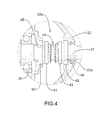
- the shaft seal 22b is mounted on the shaft 21.
- the shaft seal 22b has a first seat 40, a second seat 41, a third seat 42, a fourth seat 43 and a spring 44.
- the first seat 40 is circular and is mounted on the shaft 21 and has an inner surface and a first friction surface 45.
- the first friction surface 45 is formed on the inner surface of the first seat 40 and faces the shaft 21.
- the second seat 41 is mounted on the shaft 21 and is adjacent to the first seat 40.
- the third seat 42 is circular and is mounted on the shaft 21 and adjacent to the oil seal 22a and has an inner surface and a second friction surface 46.
- the second friction surface 46 is formed on the inner surface of the third seat 42 and faces the shaft 21.
- the fourth seat 43 is mounted on the shaft 21 and is adjacent to the third seat 42.
- the spring 44 is mounted on the shaft 21 and two ends of the spring 44 respectively abut against the second seat 41 and the fourth seat 43.
- a lubricant can flow through the first friction surface 45 and the second friction surface 46 to lubricate.
- the spring 44 can push the second seat 41 and fourth seat 43 to enhance the sealing tightness.
- the shaft seal 22b is adjacent to the second end 122 of the inner shell 12 that is under negative pressure condition, so the hydraulic pressure applied to the shaft seal 22b is low.
- the inlet 111 and the outlet 112 are respectively mounted at two sides of the outer shell 11, and the first end 121 of the inner shell 12 faces the inlet 111 of the outer shell 11. Therefore, the first end 121 of the inner shell 12 can bear more hydraulic pressure regardless of waterproofness of the first end 121 of the inner shell 12.
- the oil seal 22a and the shaft seal 22b are adjacent to the second end 122 of the inner shell 12 that is under a negative pressure condition.
- the oil seal 22a and the shaft seal 22b are not directly impacted by water flowing in the channel 13 and do not bear a hydraulic pressure of the centrifugal vortex generated by the impeller 30,
- the hydraulic pressure applied to the oil seal 22a and the shaft seal 22b are lower than the hydraulic pressure applied to the first end 121.
- a tightness degree between the shaft 21 and the shaft seal 22b is reduced and can prevent an abrasion between the shaft 21 and the shaft seal 22b and increase the waterproof effect.
- water flowing through the channel 13 around the inner shell 12 can absorb the heat generated by the driving device 20 to provide good heat dissipation.
Landscapes
- Engineering & Computer Science (AREA)
- Mechanical Engineering (AREA)
- General Engineering & Computer Science (AREA)
- Physics & Mathematics (AREA)
- Thermal Sciences (AREA)
- Structures Of Non-Positive Displacement Pumps (AREA)
Applications Claiming Priority (1)
| Application Number | Priority Date | Filing Date | Title |
|---|---|---|---|
| TW100217953U TWM425182U (en) | 2011-09-26 | 2011-09-26 | Water cooling low wear pump |
Publications (2)
| Publication Number | Publication Date |
|---|---|
| EP2573401A2 true EP2573401A2 (fr) | 2013-03-27 |
| EP2573401A3 EP2573401A3 (fr) | 2014-04-02 |
Family
ID=46462347
Family Applications (1)
| Application Number | Title | Priority Date | Filing Date |
|---|---|---|---|
| EP12185115.8A Withdrawn EP2573401A3 (fr) | 2011-09-26 | 2012-09-19 | Pompe pour liquide de refroidissement |
Country Status (2)
| Country | Link |
|---|---|
| EP (1) | EP2573401A3 (fr) |
| TW (1) | TWM425182U (fr) |
Cited By (4)
| Publication number | Priority date | Publication date | Assignee | Title |
|---|---|---|---|---|
| DE102014113412B3 (de) * | 2014-09-17 | 2015-09-24 | Nidec Gpm Gmbh | Strömungsgekühlte Kühlmittelpumpe mit Nassläufer |
| CN105570147A (zh) * | 2014-10-13 | 2016-05-11 | 上海熊猫机械集团环保科技有限公司 | 一种热能泵 |
| CN106895006A (zh) * | 2017-03-24 | 2017-06-27 | 林嘉佳 | 一种防水陆地泵 |
| CN115717597A (zh) * | 2021-08-26 | 2023-02-28 | 春鸿电子科技(重庆)有限公司 | 液冷头 |
Families Citing this family (1)
| Publication number | Priority date | Publication date | Assignee | Title |
|---|---|---|---|---|
| CN106152473A (zh) * | 2015-04-03 | 2016-11-23 | 上海熊猫机械集团环保科技有限公司 | 一种节能供暖设备 |
Family Cites Families (5)
| Publication number | Priority date | Publication date | Assignee | Title |
|---|---|---|---|---|
| GB1009823A (en) * | 1962-05-18 | 1965-11-10 | Mowid Anstalt | Submersible centrifugal waste pump |
| JPH03206389A (ja) * | 1989-09-14 | 1991-09-09 | Kaname Miura | ポンプ |
| CN2151287Y (zh) * | 1992-08-12 | 1993-12-29 | 汤生荣 | 可调立式型防腐蚀离心泵 |
| JP4557536B2 (ja) * | 2003-12-05 | 2010-10-06 | 新明和工業株式会社 | ポンプ装置 |
| GB0411040D0 (en) * | 2004-05-18 | 2004-06-23 | Weir Pumps Ltd | Pump assembly |
-
2011
- 2011-09-26 TW TW100217953U patent/TWM425182U/zh not_active IP Right Cessation
-
2012
- 2012-09-19 EP EP12185115.8A patent/EP2573401A3/fr not_active Withdrawn
Non-Patent Citations (1)
| Title |
|---|
| None |
Cited By (4)
| Publication number | Priority date | Publication date | Assignee | Title |
|---|---|---|---|---|
| DE102014113412B3 (de) * | 2014-09-17 | 2015-09-24 | Nidec Gpm Gmbh | Strömungsgekühlte Kühlmittelpumpe mit Nassläufer |
| CN105570147A (zh) * | 2014-10-13 | 2016-05-11 | 上海熊猫机械集团环保科技有限公司 | 一种热能泵 |
| CN106895006A (zh) * | 2017-03-24 | 2017-06-27 | 林嘉佳 | 一种防水陆地泵 |
| CN115717597A (zh) * | 2021-08-26 | 2023-02-28 | 春鸿电子科技(重庆)有限公司 | 液冷头 |
Also Published As
| Publication number | Publication date |
|---|---|
| EP2573401A3 (fr) | 2014-04-02 |
| TWM425182U (en) | 2012-03-21 |
Similar Documents
| Publication | Publication Date | Title |
|---|---|---|
| AU2013357653B2 (en) | Cooling arrangement of a pump intended for pumping a liquid | |
| CN103047134B (zh) | 一种气隙非浸油式液压电机叶片泵 | |
| TWM425182U (en) | Water cooling low wear pump | |
| CN203230620U (zh) | 一种离心式电动水泵的防摩擦装置 | |
| EP3255277B1 (fr) | Dispositif de perfusion sous pression et système de refroidissement de liquide | |
| CN107781174A (zh) | 一种新型电机下置式高效潜水轴流泵 | |
| EP3714166B1 (fr) | Pompe hydraulique à axe courbé et à assistance centrifuge | |
| KR20100050986A (ko) | 수중모터펌프 | |
| RU146402U1 (ru) | Электронасос прямоточный лопастной с полым валом ротора | |
| KR102902302B1 (ko) | 듀얼 구동 펌프 및 급수 시스템 | |
| CN206299497U (zh) | 油泵的叶轮泵体、油泵总成和燃油泵总成 | |
| CN104285086B (zh) | 用于转矩变换器的密封组件 | |
| CN202851377U (zh) | 一种新型立式砂泵 | |
| CN110762024A (zh) | 一种具有陶瓷轴系的超薄微型泵 | |
| CN202301053U (zh) | 水冷式低磨耗泵 | |
| CN104074793A (zh) | 离心泵的双润滑式止推轴承装置 | |
| CN210623111U (zh) | 一种潜水泵结构 | |
| CN109026826A (zh) | 一种降噪自吸泵 | |
| CN201144858Y (zh) | 一种新型离心泵用密封环 | |
| CN206054313U (zh) | 双涡壳导流机构型多级离心泵 | |
| JP7159896B2 (ja) | 水中ポンプ | |
| CN108223422B (zh) | 一种离心泵闭式叶轮前密封结构 | |
| JP2013019346A (ja) | 水中ポンプ | |
| CN202431590U (zh) | 一种空间导叶式长轴泵的密封结构 | |
| RU2493439C1 (ru) | Центробежный насос |
Legal Events
| Date | Code | Title | Description |
|---|---|---|---|
| PUAI | Public reference made under article 153(3) epc to a published international application that has entered the european phase |
Free format text: ORIGINAL CODE: 0009012 |
|
| AK | Designated contracting states |
Kind code of ref document: A2 Designated state(s): AL AT BE BG CH CY CZ DE DK EE ES FI FR GB GR HR HU IE IS IT LI LT LU LV MC MK MT NL NO PL PT RO RS SE SI SK SM TR |
|
| AX | Request for extension of the european patent |
Extension state: BA ME |
|
| PUAL | Search report despatched |
Free format text: ORIGINAL CODE: 0009013 |
|
| AK | Designated contracting states |
Kind code of ref document: A3 Designated state(s): AL AT BE BG CH CY CZ DE DK EE ES FI FR GB GR HR HU IE IS IT LI LT LU LV MC MK MT NL NO PL PT RO RS SE SI SK SM TR |
|
| AX | Request for extension of the european patent |
Extension state: BA ME |
|
| RIC1 | Information provided on ipc code assigned before grant |
Ipc: F04D 29/58 20060101ALI20140225BHEP Ipc: F04D 13/06 20060101AFI20140225BHEP Ipc: F04D 29/42 20060101ALI20140225BHEP |
|
| STAA | Information on the status of an ep patent application or granted ep patent |
Free format text: STATUS: THE APPLICATION IS DEEMED TO BE WITHDRAWN |
|
| 18D | Application deemed to be withdrawn |
Effective date: 20141003 |