EP2573414A2 - Système et procédé pour régler la fréquence de torsion d'un groupe motopropulseur - Google Patents
Système et procédé pour régler la fréquence de torsion d'un groupe motopropulseur Download PDFInfo
- Publication number
- EP2573414A2 EP2573414A2 EP12184387A EP12184387A EP2573414A2 EP 2573414 A2 EP2573414 A2 EP 2573414A2 EP 12184387 A EP12184387 A EP 12184387A EP 12184387 A EP12184387 A EP 12184387A EP 2573414 A2 EP2573414 A2 EP 2573414A2
- Authority
- EP
- European Patent Office
- Prior art keywords
- load coupling
- power train
- flange
- annular ring
- load
- Prior art date
- Legal status (The legal status is an assumption and is not a legal conclusion. Google has not performed a legal analysis and makes no representation as to the accuracy of the status listed.)
- Granted
Links
Images




Classifications
-
- F—MECHANICAL ENGINEERING; LIGHTING; HEATING; WEAPONS; BLASTING
- F16—ENGINEERING ELEMENTS AND UNITS; GENERAL MEASURES FOR PRODUCING AND MAINTAINING EFFECTIVE FUNCTIONING OF MACHINES OR INSTALLATIONS; THERMAL INSULATION IN GENERAL
- F16F—SPRINGS; SHOCK-ABSORBERS; MEANS FOR DAMPING VIBRATION
- F16F7/00—Vibration-dampers; Shock-absorbers
- F16F7/10—Vibration-dampers; Shock-absorbers using inertia effect
-
- F—MECHANICAL ENGINEERING; LIGHTING; HEATING; WEAPONS; BLASTING
- F16—ENGINEERING ELEMENTS AND UNITS; GENERAL MEASURES FOR PRODUCING AND MAINTAINING EFFECTIVE FUNCTIONING OF MACHINES OR INSTALLATIONS; THERMAL INSULATION IN GENERAL
- F16D—COUPLINGS FOR TRANSMITTING ROTATION; CLUTCHES; BRAKES
- F16D1/00—Couplings for rigidly connecting two coaxial shafts or other movable machine elements
- F16D1/02—Couplings for rigidly connecting two coaxial shafts or other movable machine elements for connecting two abutting shafts or the like
- F16D1/033—Couplings for rigidly connecting two coaxial shafts or other movable machine elements for connecting two abutting shafts or the like by clamping together two faces perpendicular to the axis of rotation, e.g. with bolted flanges
-
- F—MECHANICAL ENGINEERING; LIGHTING; HEATING; WEAPONS; BLASTING
- F16—ENGINEERING ELEMENTS AND UNITS; GENERAL MEASURES FOR PRODUCING AND MAINTAINING EFFECTIVE FUNCTIONING OF MACHINES OR INSTALLATIONS; THERMAL INSULATION IN GENERAL
- F16F—SPRINGS; SHOCK-ABSORBERS; MEANS FOR DAMPING VIBRATION
- F16F7/00—Vibration-dampers; Shock-absorbers
- F16F7/10—Vibration-dampers; Shock-absorbers using inertia effect
- F16F7/1034—Vibration-dampers; Shock-absorbers using inertia effect of movement of a liquid
-
- F—MECHANICAL ENGINEERING; LIGHTING; HEATING; WEAPONS; BLASTING
- F16—ENGINEERING ELEMENTS AND UNITS; GENERAL MEASURES FOR PRODUCING AND MAINTAINING EFFECTIVE FUNCTIONING OF MACHINES OR INSTALLATIONS; THERMAL INSULATION IN GENERAL
- F16B—DEVICES FOR FASTENING OR SECURING CONSTRUCTIONAL ELEMENTS OR MACHINE PARTS TOGETHER, e.g. NAILS, BOLTS, CIRCLIPS, CLAMPS, CLIPS OR WEDGES; JOINTS OR JOINTING
- F16B2200/00—Constructional details of connections not covered for in other groups of this subclass
- F16B2200/50—Flanged connections
-
- Y—GENERAL TAGGING OF NEW TECHNOLOGICAL DEVELOPMENTS; GENERAL TAGGING OF CROSS-SECTIONAL TECHNOLOGIES SPANNING OVER SEVERAL SECTIONS OF THE IPC; TECHNICAL SUBJECTS COVERED BY FORMER USPC CROSS-REFERENCE ART COLLECTIONS [XRACs] AND DIGESTS
- Y10—TECHNICAL SUBJECTS COVERED BY FORMER USPC
- Y10T—TECHNICAL SUBJECTS COVERED BY FORMER US CLASSIFICATION
- Y10T74/00—Machine element or mechanism
- Y10T74/21—Elements
- Y10T74/2121—Flywheel, motion smoothing-type
-
- Y—GENERAL TAGGING OF NEW TECHNOLOGICAL DEVELOPMENTS; GENERAL TAGGING OF CROSS-SECTIONAL TECHNOLOGIES SPANNING OVER SEVERAL SECTIONS OF THE IPC; TECHNICAL SUBJECTS COVERED BY FORMER USPC CROSS-REFERENCE ART COLLECTIONS [XRACs] AND DIGESTS
- Y10—TECHNICAL SUBJECTS COVERED BY FORMER USPC
- Y10T—TECHNICAL SUBJECTS COVERED BY FORMER US CLASSIFICATION
- Y10T74/00—Machine element or mechanism
- Y10T74/21—Elements
- Y10T74/2121—Flywheel, motion smoothing-type
- Y10T74/2122—Flywheel, motion smoothing-type with fluid balancing means
Definitions
- the invention relates generally to compensating for torsional frequency in a power train or other systems including rotating bodies.
- Power trains are typically mechanical and electrical systems that generate and deliver power.
- An example of a power train is a turbine and generator coupled by a load coupling. The turbine applies torque to the load coupling which drives the generator that produces electrical power.
- Vibrations in the power train are induced by cyclical variations in the torque or other forces applied to or by the power train. If the frequencies of these cyclical variations coincide with the natural frequencies of the power train, the cyclical variations may cause excessive torsional vibrations in the power train.
- Power trains are often designed to operate away from their torsional natural frequencies. Despite well intentioned designs, power trains may experience cyclical variations in torque at frequencies at or near the natural frequencies. Under these cyclical variations, the power train may excessively vibrate and be damaged. There is a long felt need for devices and methods to adjust the inertia and natural torsional frequencies of a power train and other rotating bodies.
- a turbine may be an industrial gas turbine or steam turbine which are large and heavy power generation units.
- the generators may be large generators used by utilities to produce electrical power. Due to their large size and mass, it is difficult to modify the turbines and generators after they have been installed sufficiently to shift the natural frequencies at which they vibrate. There is a long felt need to adjust the inertia and natural torsional frequencies of industrial power trains that does not require substantial changes to the turbines or generators.
- a device and method has been developed to modify the torsional natural frequency of a power train.
- the device allows for modification of the moment of inertia of the power train.
- the moment of inertia may be adjusted by arranging masses positioned in an annular array around a flange of the load coupling. By removing, adding or changing the masses, the moment of inertia of the load coupling is changed. A change in the moment of inertia moves the torsional natural frequencies for the load coupling and power train.
- the torsional natural frequencies of the power train may be adjusted to provide adequate torsional frequency margins for the power train during expected operational conditions.
- a load coupling device for a power train which includes: a rotatable shaft; a first flange on a first end of the shaft, wherein the first flange is adapted to couple to a first rotating shaft of a torque producing power supply or a torque driven power load; a second flange on an opposite end of the shaft, wherein the shaft is adapted to couple to a second rotating shaft of the other of the torque power supply and the torque driven power load, and an additional mass added to the first flange, wherein the additional mass is selected to shift a torsional natural frequency of the power train away from an operational condition of the power train.
- the additional mass may be an annular ring extending radially outward from a coupling region of the first flange, wherein the coupling region of the first flange receives fasteners to secure the first flange to a flange of the first rotating shaft.
- the annular ring may be integral with the first flange, wherein the load coupling is adapted to be substituted for an existing load coupling in the power train.
- the annular ring may be fitted to an outer circumference of the first flange.
- the load coupling device may further include trim masses adapted to be sequentially added to the additional mass.
- the trim masses may be plugs arranged in an annular array, rings or plates arranged in an annular array.
- the plugs may be removable trim mass plugs arranged in a circular array in the annular ring.
- a load coupling device has been conceived for a power train comprising: a rotatable shaft; a first flange on a first end of the shaft, wherein the first flange is adapted to couple to a first rotating shaft of a torque producing turbine or a torque driven electrical generator; a second flange on an opposite end of the shaft, wherein the shaft is adapted to couple to a second rotating shaft of the other of the turbine and the generator, and an annular ring extending radially outward from the first flange, wherein the mass of the annular ring is selected to shift a torsional natural frequency of the power train away from an operational condition of the power train.
- a power train has been conceived comprising: a torque producing power source including a rotating connecting flange; a torque driven power load including a rotating connecting flange; a load coupling having a first flange adapted to couple to the connecting flange of one of the torque producing power source and the torque driven power load; a second flange on load coupling adapted to couple to the coupling flange of the other of the torque producing power source or the torque driven power load, and an additional mass added to at least one of the connecting flanges or the load coupling wherein the additional mass is selected to shift a torsional natural frequency of the power train away from an operational condition of the power train.
- a method has been conceived to shift a torsional natural frequency of a power train including a load coupling the torque output of a turbine to drive an electrical generator, the method comprising: determining the power train has a torsional natural frequency which is excessively excited during an anticipated operational condition of the power train; adding an annular ring or annular array to the load coupling to shift the torsional natural frequency response of the power train, and determining if the power train operating with the load coupling having the annular ring or the annular array does not excessively excite the shifted torsional natural frequency during the anticipated operational conditions of the power train.
- FIGURE 1 is a schematic illustration of a conventional power train having a steam or gas turbine 10 with a rotor shaft 12, which is attached to a first end of a load coupling 14. The opposite end of the load coupling is attached to the rotor 16 of an electrical generator 18.
- the power train will be typically designed such that its operating conditions avoid the torsional natural frequencies.
- the normal operating rotating speed of the rotors and load coupling may be selected to avoid the torsional natural frequencies of the power train.
- the design requirements of the power train may include margins each centered on a torsional natural frequency. The power train is to be operated at rotational speeds that avoid these margins so as to avoid exciting the torsional natural frequencies.
- the power train has one or more natural frequencies which may be excited by torsional vibrations occurring at or near a torsional natural frequency.
- the natural frequencies of the power train are dependent on the inertia of the power train.
- the inertia of the load coupling is a component of the inertia of the power train. Because the inertia of the load coupling affects the natural frequencies of the power train, the natural frequencies of the power train may be adjusted by changing the inertia of the load coupling.
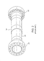
- FIGURE 2 shows a conventional load coupling 14 having annular flanges 20, 22 at opposite ends of a cylindrical drive shaft 24.
- the flanges include holes that receive bolts or other fasteners to attach to a mating flange at the end of the rotors of the turbine and generator.
- the load coupling transfers the torque applied by the rotor for the turbine to drive the rotor for the generator.
- the conventional load coupling 14 does not offer the ability to adjust the mass or inertia of the load coupling.
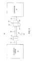
- FIGURE 3 shows a power train 26 including a steam or gas turbine 10 having a rotor 12, a load coupling 28, an electrical generator 18 with a rotor shaft 16.
- the load coupling 28 may include a normal sized flange 20 which couples to a similarly sized flange 30 on the rotor shaft for either the turbine or generator.
- the flange 32 on the opposite end of the load coupling 28 may be oversized or have mass attachments 34 on its circumference.
- the radially inward region of the flange 32 may attach to a similarly sized flange 36 on the rotor for the generator or turbine.
- the flange which is oversized or has a ring or other mass attachment may be the flanges on the rotor for the turbine or generator.
- the flange which is oversized or has a mass attachment may be coupled to one or more of the shafts 12, 38 and 16 for the turbine, load coupling and generator.
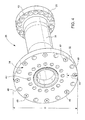
- FIGURE 4 is a perspective view of the front and side of the load coupling 28 having an oversized flange 32.
- the oversized flange may have a substantially larger diameter (D).
- the radially inward circular array of holes 40 receive the bolts that couple the load coupling to the rotor shaft of the turbine or generator.
- a similar array of bolt holes 42 are on the flange 20 at the opposite end of the load coupling.
- a radially outer region 44 of the large sized flange 32 has an adjustable mass and hence adjustable inertia.
- the adjustable mass is provided by mass plugs 46 inserted in a circular array of holes 48, e.g., threaded holes, in the outer region 44.
- the plugs 46 may be removable from the holes 48, and may be inserted in all of the holes 48 in the circular array.
- the increased diameter of the flange 32 results in a different inertia for the load coupling 28 as compared to the inertia of the conventional load coupling 14.
- the change in inertia due to substituting the load coupling 28 for the conventional load coupling 14 may be used to shift the torsional natural frequencies of the power train.
- the shift in the inertia will change the natural frequencies of power train.
- the shift in the natural frequency is intended to avoid the frequencies of torsional vibrations applied to or generated by the power train.
- the intended shift in the natural frequencies by rearranging and replacing the plugs should result in a power train which does not experience excessive torsional vibration and has sufficient torsional frequency margin.
- plugs, rings or other additional masses may be added to the outer radial portion of one or more flanges associated with the load coupling or the rotor shafts for the turbine or generator.
- a substitute load coupling 28 or masses added to the perimeter of an existing flange, such as on the in-place load coupling, may be installed without moving the turbine or generator and without making substantial changes to other components adjacent the load coupling.
- the existing load coupling 14 may be unbolted from the rotors 12, 16 of the turbine and generator, and removed by a crane.
- the substitute load coupling 28 with large diameter flange 32 may be positioned by the crane between the rotor shafts 12, 16 such that the bolt openings 40, 42 are aligned with the bolt openings in the rotor shaft flanges for the turbine and generator. Bolts are inserted through the bolt openings to couple the load coupling 28 to the rotor shafts 12, 16 of the turbine and generator.
- Plugs 46 having various masses may be available for insertion in the holes 48.
- the plugs may be used to tune the frequency response of the power train and, particularly, shift its torsional natural frequencies.
- the plugs 46 inserted in all of the holes 48 may each have substantially the same density, e.g., formed of the same material, as the material forming the large sized flange 32. If a determination is made during initial testing of the power train or at other time that a change is needed to the natural frequencies of the power train, the plugs 46 may be replaced by alternative plugs having a different mass, e.g., less dense, than the plugs initially installed in the holes 48. Changing the density of the plugs will cause the inertia of the load coupling and the power train to shift.
- FIGURE 5 is a perspective view of a side and front of an exemplary plug 46.
- the plug 46 may be a portion of a threaded rod, such that the threaded outer surface 50 of the plug engages threads on the inner cylindrical surface of the holes 48 in the flange 32.
- the plug may be circular in cross-section and have straight, center axis.
- a hexed recess 52 is aligned with the axis and in the front surface of the plug.
- the hexed recess 52 receives a hexed end tool which is used to insert and remove the plug from the holes 48 in the flange.
- the plugs 46 may be replaced and rearranged relatively easily and without disassembling other components of the power train.
- the plugs 46 are an example of a trim mass that may be used to make fine adjustments to the frequency response of the power train.
- the trim masses may be used in addition to adding a larger mass to the load coupling to shift the torsional frequency natural modes of the power train.
- the trim masses may be included in a load coupling provided with the initial installation of a power train.
- FIGURE 6 is a cross-sectional view of a conventional load coupling 14 having a ring mass 53 attached to the perimeter of one of the flanges 22 of the load coupling.
- the ring mass 53 changes the inertia of the load coupling and hence shifts the torsional natural frequencies of the power train that includes the load coupling.
- the ring mass 53 may be metallic and formed of substantially the same metal as the load coupling.
- the ring mass 53 may be press fitted and heat shrunk on the flange 22.
- the ring mass may be heated to cause it to expand. While expanded, the ring mass is moved in an axial direction to be pressed onto the outer circumference of the flange 22.
- This press fitting may be performed after segments of the ring mass have been welded to form an annulus around the shaft of the load coupling or after the load coupling has been disconnected from the rotor shaft of the turbine or generator. As the ring mass cools and shrinks onto the perimeter of the flange 22.
- An annular weld 54 may secure the ring mass to the flange 22.
- Additional mass may be added to the load coupling 14 by one or more stacking ring masses with the first ring mass 53.
- the additional ring masses 56 may be stacked axially with the first ring mass 53.
- a clamp 58 may secure the ring masses 56, 53 together.
- the ring masses may be mounted radially, e.g., superimposed, with each ring having a diameter slightly larger than the prior ring.
- the additional ring masses 56 may be added sequentially with the vibration frequency response of the power train tested between each application of a ring mass. When the frequency response of the power train is acceptable, such as when the power train has sufficient torsional frequency margins.
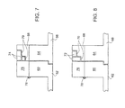
- FIGURES 7 and 8 are cross-sectional views of further embodiments of additional masses added to the flanges 60 of a load coupling 62 and flanges 64 of a generator or turbine shaft 66.
- the load coupling and flanges are shown only partially in Figures 7 and 8 .
- An annular ring mass 68 may be integral with one of the flanges 60, 64 or may be fitted onto one or both of these flanges.
- the perimeter of the ring mass 68 includes one or more stepped ledges 70.
- Additional ring masses 72, 74 may be seated on the ledges 70.
- the ring masses 72 may be stacked axially as shown in Figure 8 or stacked radially 74 as shown in Figure 7 . Further the ring masses may have different masses such as by having different cross-sectional shapes.
- the ring masses 68, 72, 74 may be formed of the same material as the flange 64 to allow for uniform thermal expansion and contraction of the rings and flanges.
- the addition of the ring mass 68 may by itself be sufficient to shift the torsional natural frequencies of the power train such that the torsional frequency margins are sufficient. If the ring mass 68 is not sufficient, the additional ring masses 72, 74 may be added sequentially to tune the frequency response of the power train and ensure adequate margins associated with the natural frequencies of the power train.
- the ring masses 68, 72 and 74 may be secured to the flange 64 by an annular ring or shank 76 that abuts the ring masses 68, 72 or 74.
- the shank 76 may be an annular array of teeth welded 78 to the flange 60.
- the ring or shank 76 may have sufficient mass to contribute to the shift in inertia and torsional natural frequencies provided by the ring masses 68, 72 or 74.
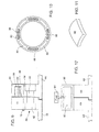
- FIGURES 9 and 10 are cross-sectional views, taken parallel to the load coupling axis and perpendicular to the axis respectively, of a further embodiment of additional masses added to the flanges 60 of a load coupling 62 and flanges 64 of a generator or turbine shaft 66.
- the ring mass 80 has an internal annular slot 82 which receives ring bands 84, 86 or plates 88 that add mass to the ring mass 80.
- the annular slot may be continuous around the flange 64 or segmented into individual chambers as shown in Figure 10 . If the slot 82 is continuous, the added masses may be the ring bands 84, 86.
- the plates 88 may be added in selected segments of the slot.
- the ring bands 84, 86 and plates 88 are added to adjust the inertia of the load coupling and thereby tune the frequency response of the power train.
- FIGURE 12 is a cross-sectional view of a further embodiment of adding mass to the flanges 60, 64 of a load coupling 62 and shaft 66 of a power train.
- An annular ring 90 with an interior chamber 92 is added to or integral with any of the flanges 60, 64. If mass needs to be added to shift the torsional natural frequencies, a liquid is pumped from a liquid source 94 into the chamber 92. The amount of fluid pumped into the chamber is determined based on the amount of mass needed to be added to shift the torsional natural frequencies of the power train and the amount of shift desired. During operation, the centrifugal force due to rotation of the ring 90 will cause the liquid to move radially outward in the chamber 92.
- FIGURE 13 is a cross-sectional diagram of a shortened load coupling 100 having normal diameter flanges 102, 104 which are bolted to the flanges 106 of the shafts 108 for the turbine and generator.
- the load coupling 100 does not extend the full distance between the ends of the shafts.
- the load coupling 100 may be substituted for an existing load coupling such as 14 in Figure 1 .
- a mass disc or ring 109 is sandwiched between the flange 102 of the load coupling and the flange 106 of the shaft 109.
- Bolts 110 extend through aligned openings in both flanges and the disc or ring 109 to couple the assembly together.
- the mass disc 109 may be a circular or annular device having a mass sufficient to change the inertia and torsional natural frequency of the power train.
- the mass disc may have a radial outward region 112 that has more mass than radially inward portions of the disc. Concentrating the mass of the disc radially outward increases the shift in torsional inertia resulting from the addition of the mass disc 109.
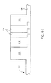
- FIGURE 14 is a cross-sectional view of a further embodiment of adding mass between the flange 102 of a load coupling 100 and the flange 106 of a shaft 108 in the power train system.
- Figure 13 shows a single disc 109 sandwiched between the flanges
- Figure 14 shows a stack of two or more rings or discs sandwiched between the flanges.
- a first disc or ring 112 may be relatively thick and add a substantial amount of mass to the load coupling and power train. The first disc or ring 112 may be selected to approximate the desired mass needed to shift the torsional natural frequencies of the power train.
- One or more thinner discs or rings 114 may be stacked between the first disc 112 and a flange 106 to tune the natural frequencies and frequency response of the power train.
- the thinner discs may have less mass, e.g., between one half to one quarter, the mass of the first disc 112.
- the thinner discs may be added sequentially and as each disc 114 is added, the power train may be tested to determine if its frequency response provides adequate margins about the torsional natural frequencies.
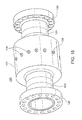
- FIGURE 15 is a perspective view of the side and an end of a load coupling 120 having, as an added mass, an annular collar 122 added to the shaft 124.
- the flanges 126 at opposite ends of the load coupling may be sized to connect to respective flanges on a turbine and a generator.
- the annular collar may be integral with the shaft of the load coupling or added, e.g., welded or clamped, to the shaft of the load coupling.
- the annular collar may be coaxial to the axis of the load coupling and aligned with the longitudinal center of the load coupling.
- the outer cylindrical surface of the annular collar may include recesses for trim masses 128.
- the trim masses 128 may be threaded plugs which are inserted in threaded openings in the annular collar.
- the trim plugs may be removed or replaced with other trim plugs having differing masses. The removal and replacement of trim plugs may be used to make fine adjustments, e.g., tune, the frequency response of the power train which includes the load coupling 120.
Landscapes
- Engineering & Computer Science (AREA)
- General Engineering & Computer Science (AREA)
- Mechanical Engineering (AREA)
- Connection Of Motors, Electrical Generators, Mechanical Devices, And The Like (AREA)
- Turbine Rotor Nozzle Sealing (AREA)
Applications Claiming Priority (1)
| Application Number | Priority Date | Filing Date | Title |
|---|---|---|---|
| US13/236,975 US8732927B2 (en) | 2011-09-20 | 2011-09-20 | Method for adjusting torsional frequency of a power train |
Publications (3)
| Publication Number | Publication Date |
|---|---|
| EP2573414A2 true EP2573414A2 (fr) | 2013-03-27 |
| EP2573414A3 EP2573414A3 (fr) | 2014-01-01 |
| EP2573414B1 EP2573414B1 (fr) | 2017-11-15 |
Family
ID=47178459
Family Applications (1)
| Application Number | Title | Priority Date | Filing Date |
|---|---|---|---|
| EP12184387.4A Active EP2573414B1 (fr) | 2011-09-20 | 2012-09-14 | Système et procédé pour régler la fréquence de torsion d'un groupe motopropulseur |
Country Status (3)
| Country | Link |
|---|---|
| US (2) | US8732927B2 (fr) |
| EP (1) | EP2573414B1 (fr) |
| CN (1) | CN103016612B (fr) |
Cited By (2)
| Publication number | Priority date | Publication date | Assignee | Title |
|---|---|---|---|---|
| US11025131B2 (en) | 2015-07-14 | 2021-06-01 | Cummins Generator Technologies Limited | Adaptor for generator |
| WO2022022773A1 (fr) * | 2020-07-28 | 2022-02-03 | MTU Aero Engines AG | Composite de serrage de rotor d'une turbomachine, ledit composite étant solidaire en rotation |
Families Citing this family (11)
| Publication number | Priority date | Publication date | Assignee | Title |
|---|---|---|---|---|
| US9551398B2 (en) * | 2013-03-15 | 2017-01-24 | General Electric Company | Torsional mode shifting |
| CN205166525U (zh) | 2013-03-15 | 2016-04-20 | 通用电气公司 | 扭转频率调节器 |
| US9518610B2 (en) | 2013-05-28 | 2016-12-13 | General Electric Company | Load coupling and method for adjusting torsional natural frequency of power train |
| US9145923B2 (en) | 2013-07-03 | 2015-09-29 | General Electric Company | Load coupling for adjusting torsional natural frequency of a power train |
| US9216495B2 (en) * | 2013-07-09 | 2015-12-22 | General Electric Company | Spacer |
| US20150192019A1 (en) * | 2014-01-07 | 2015-07-09 | General Electric Company | Rotor train torsional mode frequency tuning apparatus |
| CN105134806A (zh) * | 2015-08-26 | 2015-12-09 | 鞍山海量有色金属材料制造有限公司 | 一种无水冷大法兰 |
| CN105370794B (zh) * | 2015-12-18 | 2018-01-16 | 环宇东海橡塑(天津)有限公司 | 双频阻尼器 |
| JP6650052B2 (ja) * | 2016-12-27 | 2020-02-19 | 株式会社バルカー | 実習システムおよび実習プログラム |
| KR20190056168A (ko) * | 2017-11-16 | 2019-05-24 | 삼성메디슨 주식회사 | 진동 감쇄 모터 조립체 및 이를 포함하는 초음파 프로브 |
| DE102019207826A1 (de) * | 2019-05-28 | 2020-12-03 | Zf Friedrichshafen Ag | Segmentierter Schwingungstilger |
Family Cites Families (36)
| Publication number | Priority date | Publication date | Assignee | Title |
|---|---|---|---|---|
| US1499618A (en) | 1921-07-12 | 1924-07-01 | Westinghouse Gear And Dynamome | Shaft coupling |
| US1645323A (en) * | 1925-10-24 | 1927-10-11 | Packard Motor Car Co | Motor vehicle |
| US1916086A (en) * | 1927-03-14 | 1933-06-27 | Packard Motor Car Co | Internal combustion engine |
| US2379175A (en) | 1943-02-18 | 1945-06-26 | Westinghouse Electric Corp | Resilient shaft coupling |
| US2593877A (en) | 1945-09-18 | 1952-04-22 | Hagenlocher Ernest | Flexible coupling |
| US2446405A (en) | 1945-10-31 | 1948-08-03 | Hazeltine Research Inc | Tunable ultra high frequency resonator system |
| GB679968A (en) | 1949-10-11 | 1952-09-24 | Vickers Electrical Co Ltd | Improvements in and relating to couplings for shafts and the like |
| US2696346A (en) | 1951-05-04 | 1954-12-07 | Bristol Aeroplane Co Ltd | Flexible shaft coupling |
| US2878689A (en) | 1957-10-09 | 1959-03-24 | Chrysler Corp | Tuned vibration damping system for drive trains |
| US3992963A (en) | 1975-01-21 | 1976-11-23 | Wallace-Murray Corporation | Elastomer and liquid torsional vibration damper |
| US4006607A (en) | 1975-08-20 | 1977-02-08 | Kane Thomas R | Constant speed ratio coupling for shafts with time-varying orientations |
| US4140028A (en) | 1977-09-13 | 1979-02-20 | The Boeing Company | Vibration isolation system |
| US4217767A (en) | 1978-10-23 | 1980-08-19 | Carrier Corporation | Apparatus for housing a shaft coupling |
| DE3134310C2 (de) * | 1981-08-29 | 1983-06-30 | Daimler-Benz Ag, 7000 Stuttgart | "Einrichtung zur Dämpfung von Schwingungen im Antriebsstrang eines Kraftfahrzeuges" |
| CH662621A5 (de) | 1983-10-24 | 1987-10-15 | Bbc Brown Boveri & Cie | Wellenkupplung. |
| US6463827B1 (en) * | 1989-12-06 | 2002-10-15 | Hans Oetikur Ag Maschinen- Und Apparatefabrik | Balancing arrangement for rotating member and method of making same |
| US4728255A (en) | 1985-02-25 | 1988-03-01 | General Electric Company | Removable stiffening disk |
| US4782936A (en) | 1987-06-05 | 1988-11-08 | Eaton Corporation | Two mass flywheel assembly with torsional damping means |
| JPH03501285A (ja) | 1988-07-22 | 1991-03-22 | ボコ フランツ‐ヨゼフ ボルフ ウント コンパニ | 回転振動ダンパ |
| GB2223083B (en) | 1988-09-27 | 1993-01-06 | Pratt & Whitney Canada | Shaft coupling for gas turbine engine |
| DE4020998A1 (de) | 1990-07-02 | 1992-01-16 | Gkn Automotive Ag | Antriebswelle |
| DE4027296A1 (de) | 1990-08-29 | 1992-03-12 | Gkn Automotive Ag | Antriebswelle mit zusatzmassen |
| US5528348A (en) | 1992-09-11 | 1996-06-18 | Konica Corporation | Damping device for rotating members |
| US5746550A (en) | 1995-10-27 | 1998-05-05 | Westinghouse Electric Corporation | Coupling reaming apparatus and method |
| US5720205A (en) * | 1995-12-15 | 1998-02-24 | Harrington; David | Viscous torsional vibration damper with multi-component housing weldment |
| US6471453B1 (en) * | 2001-05-25 | 2002-10-29 | Kennametal Inc. | Balancing assembly for a rotating member |
| US6795779B2 (en) * | 2002-09-06 | 2004-09-21 | General Electric Company | High resolution torque measurement on a rotating shaft |
| US6889803B2 (en) * | 2002-10-11 | 2005-05-10 | American Axle & Manufacturing, Inc. | Torsional active vibration control system |
| EP1715205B1 (fr) | 2003-11-21 | 2013-04-03 | NTN Corporation | Accouplement d'arbres |
| US20060223640A1 (en) | 2005-04-05 | 2006-10-05 | Bassett Michael L | Rotational coupling with overload protection |
| US20070188026A1 (en) | 2006-01-31 | 2007-08-16 | Zhongshan Broad-Ocean Motor Co., Ltd. | Damping structure for a rotor assembly of a motor |
| DE102008006782B3 (de) * | 2007-12-20 | 2009-04-09 | Tedrive Holding B.V. | Verbesserter Schwingungstilger für rotierende Wellen |
| US8480054B2 (en) | 2008-05-30 | 2013-07-09 | Woodward, Inc. | Tortionally stiff, thermally isolating shaft coupling with multiple degrees of freedom to accommodate misalignment |
| US8344673B2 (en) | 2008-12-04 | 2013-01-01 | Nuovo Pignone S.P.A. | Torsional mode damping apparatus |
| US9518610B2 (en) * | 2013-05-28 | 2016-12-13 | General Electric Company | Load coupling and method for adjusting torsional natural frequency of power train |
| US9145923B2 (en) * | 2013-07-03 | 2015-09-29 | General Electric Company | Load coupling for adjusting torsional natural frequency of a power train |
-
2011
- 2011-09-20 US US13/236,975 patent/US8732927B2/en active Active
-
2012
- 2012-09-14 EP EP12184387.4A patent/EP2573414B1/fr active Active
- 2012-09-20 CN CN201210352259.3A patent/CN103016612B/zh active Active
-
2014
- 2014-05-19 US US14/281,573 patent/US10030734B2/en active Active
Non-Patent Citations (1)
| Title |
|---|
| None |
Cited By (2)
| Publication number | Priority date | Publication date | Assignee | Title |
|---|---|---|---|---|
| US11025131B2 (en) | 2015-07-14 | 2021-06-01 | Cummins Generator Technologies Limited | Adaptor for generator |
| WO2022022773A1 (fr) * | 2020-07-28 | 2022-02-03 | MTU Aero Engines AG | Composite de serrage de rotor d'une turbomachine, ledit composite étant solidaire en rotation |
Also Published As
| Publication number | Publication date |
|---|---|
| US10030734B2 (en) | 2018-07-24 |
| CN103016612A (zh) | 2013-04-03 |
| US8732927B2 (en) | 2014-05-27 |
| EP2573414A3 (fr) | 2014-01-01 |
| EP2573414B1 (fr) | 2017-11-15 |
| US20140251074A1 (en) | 2014-09-11 |
| CN103016612B (zh) | 2016-10-12 |
| US20130071180A1 (en) | 2013-03-21 |
Similar Documents
| Publication | Publication Date | Title |
|---|---|---|
| US8732927B2 (en) | Method for adjusting torsional frequency of a power train | |
| RU2419724C1 (ru) | Ротор газовой турбины и тепловая лопаточная машина с таким ротором | |
| KR101624054B1 (ko) | 복수 개의 타이로드를 구비한 가스터빈 및 그의 조립방법 | |
| JP2010273535A (ja) | 発電機ステータ取付けのためのシステムおよび方法 | |
| US20100295407A1 (en) | Apparatus for generator stator mounting | |
| EP2192299B1 (fr) | Accouplement d'arbres dans une éolienne | |
| US8421318B2 (en) | Rotor of rotating electrical machine | |
| CN102705436A (zh) | 用于旋转体的分段式调节环 | |
| WO2011018413A1 (fr) | Diaphragmes de turbine | |
| EP3278027B1 (fr) | Chambre de combustion de turbine à gaz avec support de chemise interchangeable | |
| EP2884628A2 (fr) | Ensembles à ressort pour supporter un noyau de stator dans une carcasse de stator | |
| EP3447322B1 (fr) | Couplage pour groupe électrogène | |
| KR102341021B1 (ko) | 로터 트레인의 비틀림 모드 진동수 조절 장치 | |
| JP6204744B2 (ja) | バランスウェイト設置システム及び関連する方法 | |
| US5209632A (en) | Hydroelectric power generation equipment | |
| EP2884627A2 (fr) | Procédé de réparation d'ensembles de ressorts dans un noyau de stator | |
| US9145923B2 (en) | Load coupling for adjusting torsional natural frequency of a power train | |
| US7083406B2 (en) | Vibration system for concrete pipe making machines | |
| JP2020089257A5 (fr) | ||
| US20140079547A1 (en) | Rotor assembly and refit method | |
| JP2014202213A (ja) | ロータ | |
| JP2023064326A (ja) | 発電プラントのロータ回転装置及び発電プラントのロータ回転方法 |
Legal Events
| Date | Code | Title | Description |
|---|---|---|---|
| PUAI | Public reference made under article 153(3) epc to a published international application that has entered the european phase |
Free format text: ORIGINAL CODE: 0009012 |
|
| AK | Designated contracting states |
Kind code of ref document: A2 Designated state(s): AL AT BE BG CH CY CZ DE DK EE ES FI FR GB GR HR HU IE IS IT LI LT LU LV MC MK MT NL NO PL PT RO RS SE SI SK SM TR |
|
| AX | Request for extension of the european patent |
Extension state: BA ME |
|
| PUAL | Search report despatched |
Free format text: ORIGINAL CODE: 0009013 |
|
| AK | Designated contracting states |
Kind code of ref document: A3 Designated state(s): AL AT BE BG CH CY CZ DE DK EE ES FI FR GB GR HR HU IE IS IT LI LT LU LV MC MK MT NL NO PL PT RO RS SE SI SK SM TR |
|
| AX | Request for extension of the european patent |
Extension state: BA ME |
|
| RIC1 | Information provided on ipc code assigned before grant |
Ipc: F16D 1/033 20060101AFI20131125BHEP |
|
| 17P | Request for examination filed |
Effective date: 20140701 |
|
| RBV | Designated contracting states (corrected) |
Designated state(s): AL AT BE BG CH CY CZ DE DK EE ES FI FR GB GR HR HU IE IS IT LI LT LU LV MC MK MT NL NO PL PT RO RS SE SI SK SM TR |
|
| 17Q | First examination report despatched |
Effective date: 20160407 |
|
| GRAP | Despatch of communication of intention to grant a patent |
Free format text: ORIGINAL CODE: EPIDOSNIGR1 |
|
| INTG | Intention to grant announced |
Effective date: 20170720 |
|
| GRAS | Grant fee paid |
Free format text: ORIGINAL CODE: EPIDOSNIGR3 |
|
| GRAA | (expected) grant |
Free format text: ORIGINAL CODE: 0009210 |
|
| AK | Designated contracting states |
Kind code of ref document: B1 Designated state(s): AL AT BE BG CH CY CZ DE DK EE ES FI FR GB GR HR HU IE IS IT LI LT LU LV MC MK MT NL NO PL PT RO RS SE SI SK SM TR |
|
| REG | Reference to a national code |
Ref country code: CH Ref legal event code: EP Ref country code: GB Ref legal event code: FG4D Ref country code: AT Ref legal event code: REF Ref document number: 946599 Country of ref document: AT Kind code of ref document: T Effective date: 20171115 |
|
| REG | Reference to a national code |
Ref country code: IE Ref legal event code: FG4D |
|
| REG | Reference to a national code |
Ref country code: DE Ref legal event code: R096 Ref document number: 602012039723 Country of ref document: DE |
|
| REG | Reference to a national code |
Ref country code: NL Ref legal event code: MP Effective date: 20171115 |
|
| REG | Reference to a national code |
Ref country code: LT Ref legal event code: MG4D |
|
| REG | Reference to a national code |
Ref country code: AT Ref legal event code: MK05 Ref document number: 946599 Country of ref document: AT Kind code of ref document: T Effective date: 20171115 |
|
| PG25 | Lapsed in a contracting state [announced via postgrant information from national office to epo] |
Ref country code: NO Free format text: LAPSE BECAUSE OF FAILURE TO SUBMIT A TRANSLATION OF THE DESCRIPTION OR TO PAY THE FEE WITHIN THE PRESCRIBED TIME-LIMIT Effective date: 20180215 Ref country code: SE Free format text: LAPSE BECAUSE OF FAILURE TO SUBMIT A TRANSLATION OF THE DESCRIPTION OR TO PAY THE FEE WITHIN THE PRESCRIBED TIME-LIMIT Effective date: 20171115 Ref country code: LT Free format text: LAPSE BECAUSE OF FAILURE TO SUBMIT A TRANSLATION OF THE DESCRIPTION OR TO PAY THE FEE WITHIN THE PRESCRIBED TIME-LIMIT Effective date: 20171115 Ref country code: FI Free format text: LAPSE BECAUSE OF FAILURE TO SUBMIT A TRANSLATION OF THE DESCRIPTION OR TO PAY THE FEE WITHIN THE PRESCRIBED TIME-LIMIT Effective date: 20171115 Ref country code: NL Free format text: LAPSE BECAUSE OF FAILURE TO SUBMIT A TRANSLATION OF THE DESCRIPTION OR TO PAY THE FEE WITHIN THE PRESCRIBED TIME-LIMIT Effective date: 20171115 Ref country code: ES Free format text: LAPSE BECAUSE OF FAILURE TO SUBMIT A TRANSLATION OF THE DESCRIPTION OR TO PAY THE FEE WITHIN THE PRESCRIBED TIME-LIMIT Effective date: 20171115 |
|
| PG25 | Lapsed in a contracting state [announced via postgrant information from national office to epo] |
Ref country code: AT Free format text: LAPSE BECAUSE OF FAILURE TO SUBMIT A TRANSLATION OF THE DESCRIPTION OR TO PAY THE FEE WITHIN THE PRESCRIBED TIME-LIMIT Effective date: 20171115 Ref country code: RS Free format text: LAPSE BECAUSE OF FAILURE TO SUBMIT A TRANSLATION OF THE DESCRIPTION OR TO PAY THE FEE WITHIN THE PRESCRIBED TIME-LIMIT Effective date: 20171115 Ref country code: HR Free format text: LAPSE BECAUSE OF FAILURE TO SUBMIT A TRANSLATION OF THE DESCRIPTION OR TO PAY THE FEE WITHIN THE PRESCRIBED TIME-LIMIT Effective date: 20171115 Ref country code: GR Free format text: LAPSE BECAUSE OF FAILURE TO SUBMIT A TRANSLATION OF THE DESCRIPTION OR TO PAY THE FEE WITHIN THE PRESCRIBED TIME-LIMIT Effective date: 20180216 Ref country code: LV Free format text: LAPSE BECAUSE OF FAILURE TO SUBMIT A TRANSLATION OF THE DESCRIPTION OR TO PAY THE FEE WITHIN THE PRESCRIBED TIME-LIMIT Effective date: 20171115 Ref country code: BG Free format text: LAPSE BECAUSE OF FAILURE TO SUBMIT A TRANSLATION OF THE DESCRIPTION OR TO PAY THE FEE WITHIN THE PRESCRIBED TIME-LIMIT Effective date: 20180215 |
|
| PG25 | Lapsed in a contracting state [announced via postgrant information from national office to epo] |
Ref country code: EE Free format text: LAPSE BECAUSE OF FAILURE TO SUBMIT A TRANSLATION OF THE DESCRIPTION OR TO PAY THE FEE WITHIN THE PRESCRIBED TIME-LIMIT Effective date: 20171115 Ref country code: CY Free format text: LAPSE BECAUSE OF FAILURE TO SUBMIT A TRANSLATION OF THE DESCRIPTION OR TO PAY THE FEE WITHIN THE PRESCRIBED TIME-LIMIT Effective date: 20171115 Ref country code: CZ Free format text: LAPSE BECAUSE OF FAILURE TO SUBMIT A TRANSLATION OF THE DESCRIPTION OR TO PAY THE FEE WITHIN THE PRESCRIBED TIME-LIMIT Effective date: 20171115 Ref country code: DK Free format text: LAPSE BECAUSE OF FAILURE TO SUBMIT A TRANSLATION OF THE DESCRIPTION OR TO PAY THE FEE WITHIN THE PRESCRIBED TIME-LIMIT Effective date: 20171115 Ref country code: SK Free format text: LAPSE BECAUSE OF FAILURE TO SUBMIT A TRANSLATION OF THE DESCRIPTION OR TO PAY THE FEE WITHIN THE PRESCRIBED TIME-LIMIT Effective date: 20171115 |
|
| REG | Reference to a national code |
Ref country code: DE Ref legal event code: R097 Ref document number: 602012039723 Country of ref document: DE |
|
| PG25 | Lapsed in a contracting state [announced via postgrant information from national office to epo] |
Ref country code: PL Free format text: LAPSE BECAUSE OF FAILURE TO SUBMIT A TRANSLATION OF THE DESCRIPTION OR TO PAY THE FEE WITHIN THE PRESCRIBED TIME-LIMIT Effective date: 20171115 Ref country code: SM Free format text: LAPSE BECAUSE OF FAILURE TO SUBMIT A TRANSLATION OF THE DESCRIPTION OR TO PAY THE FEE WITHIN THE PRESCRIBED TIME-LIMIT Effective date: 20171115 Ref country code: RO Free format text: LAPSE BECAUSE OF FAILURE TO SUBMIT A TRANSLATION OF THE DESCRIPTION OR TO PAY THE FEE WITHIN THE PRESCRIBED TIME-LIMIT Effective date: 20171115 |
|
| PLBE | No opposition filed within time limit |
Free format text: ORIGINAL CODE: 0009261 |
|
| STAA | Information on the status of an ep patent application or granted ep patent |
Free format text: STATUS: NO OPPOSITION FILED WITHIN TIME LIMIT |
|
| 26N | No opposition filed |
Effective date: 20180817 |
|
| PG25 | Lapsed in a contracting state [announced via postgrant information from national office to epo] |
Ref country code: SI Free format text: LAPSE BECAUSE OF FAILURE TO SUBMIT A TRANSLATION OF THE DESCRIPTION OR TO PAY THE FEE WITHIN THE PRESCRIBED TIME-LIMIT Effective date: 20171115 |
|
| PG25 | Lapsed in a contracting state [announced via postgrant information from national office to epo] |
Ref country code: MC Free format text: LAPSE BECAUSE OF FAILURE TO SUBMIT A TRANSLATION OF THE DESCRIPTION OR TO PAY THE FEE WITHIN THE PRESCRIBED TIME-LIMIT Effective date: 20171115 |
|
| REG | Reference to a national code |
Ref country code: CH Ref legal event code: PL |
|
| GBPC | Gb: european patent ceased through non-payment of renewal fee |
Effective date: 20180914 |
|
| REG | Reference to a national code |
Ref country code: BE Ref legal event code: MM Effective date: 20180930 |
|
| REG | Reference to a national code |
Ref country code: IE Ref legal event code: MM4A |
|
| PG25 | Lapsed in a contracting state [announced via postgrant information from national office to epo] |
Ref country code: LU Free format text: LAPSE BECAUSE OF NON-PAYMENT OF DUE FEES Effective date: 20180914 |
|
| PG25 | Lapsed in a contracting state [announced via postgrant information from national office to epo] |
Ref country code: IE Free format text: LAPSE BECAUSE OF NON-PAYMENT OF DUE FEES Effective date: 20180914 |
|
| PG25 | Lapsed in a contracting state [announced via postgrant information from national office to epo] |
Ref country code: LI Free format text: LAPSE BECAUSE OF NON-PAYMENT OF DUE FEES Effective date: 20180930 Ref country code: CH Free format text: LAPSE BECAUSE OF NON-PAYMENT OF DUE FEES Effective date: 20180930 Ref country code: FR Free format text: LAPSE BECAUSE OF NON-PAYMENT OF DUE FEES Effective date: 20180930 Ref country code: BE Free format text: LAPSE BECAUSE OF NON-PAYMENT OF DUE FEES Effective date: 20180930 |
|
| PG25 | Lapsed in a contracting state [announced via postgrant information from national office to epo] |
Ref country code: GB Free format text: LAPSE BECAUSE OF NON-PAYMENT OF DUE FEES Effective date: 20180914 |
|
| PG25 | Lapsed in a contracting state [announced via postgrant information from national office to epo] |
Ref country code: MT Free format text: LAPSE BECAUSE OF NON-PAYMENT OF DUE FEES Effective date: 20180914 |
|
| PG25 | Lapsed in a contracting state [announced via postgrant information from national office to epo] |
Ref country code: TR Free format text: LAPSE BECAUSE OF FAILURE TO SUBMIT A TRANSLATION OF THE DESCRIPTION OR TO PAY THE FEE WITHIN THE PRESCRIBED TIME-LIMIT Effective date: 20171115 |
|
| PG25 | Lapsed in a contracting state [announced via postgrant information from national office to epo] |
Ref country code: HU Free format text: LAPSE BECAUSE OF FAILURE TO SUBMIT A TRANSLATION OF THE DESCRIPTION OR TO PAY THE FEE WITHIN THE PRESCRIBED TIME-LIMIT; INVALID AB INITIO Effective date: 20120914 Ref country code: PT Free format text: LAPSE BECAUSE OF FAILURE TO SUBMIT A TRANSLATION OF THE DESCRIPTION OR TO PAY THE FEE WITHIN THE PRESCRIBED TIME-LIMIT Effective date: 20171115 |
|
| PG25 | Lapsed in a contracting state [announced via postgrant information from national office to epo] |
Ref country code: MK Free format text: LAPSE BECAUSE OF NON-PAYMENT OF DUE FEES Effective date: 20171115 |
|
| PG25 | Lapsed in a contracting state [announced via postgrant information from national office to epo] |
Ref country code: AL Free format text: LAPSE BECAUSE OF FAILURE TO SUBMIT A TRANSLATION OF THE DESCRIPTION OR TO PAY THE FEE WITHIN THE PRESCRIBED TIME-LIMIT Effective date: 20171115 Ref country code: IS Free format text: LAPSE BECAUSE OF FAILURE TO SUBMIT A TRANSLATION OF THE DESCRIPTION OR TO PAY THE FEE WITHIN THE PRESCRIBED TIME-LIMIT Effective date: 20180315 |
|
| P01 | Opt-out of the competence of the unified patent court (upc) registered |
Effective date: 20230522 |
|
| REG | Reference to a national code |
Ref country code: DE Ref legal event code: R081 Ref document number: 602012039723 Country of ref document: DE Owner name: GENERAL ELECTRIC TECHNOLOGY GMBH, CH Free format text: FORMER OWNER: GENERAL ELECTRIC COMPANY, SCHENECTADY, NY, US |
|
| PGFP | Annual fee paid to national office [announced via postgrant information from national office to epo] |
Ref country code: DE Payment date: 20250820 Year of fee payment: 14 |
|
| PGFP | Annual fee paid to national office [announced via postgrant information from national office to epo] |
Ref country code: IT Payment date: 20250820 Year of fee payment: 14 |