EP2573420A2 - Bicyclette avec suspension - Google Patents
Bicyclette avec suspension Download PDFInfo
- Publication number
- EP2573420A2 EP2573420A2 EP12184196A EP12184196A EP2573420A2 EP 2573420 A2 EP2573420 A2 EP 2573420A2 EP 12184196 A EP12184196 A EP 12184196A EP 12184196 A EP12184196 A EP 12184196A EP 2573420 A2 EP2573420 A2 EP 2573420A2
- Authority
- EP
- European Patent Office
- Prior art keywords
- air chamber
- valve
- shock
- secondary air
- main air
- Prior art date
- Legal status (The legal status is an assumption and is not a legal conclusion. Google has not performed a legal analysis and makes no representation as to the accuracy of the status listed.)
- Withdrawn
Links
Images


Classifications
-
- B—PERFORMING OPERATIONS; TRANSPORTING
- B62—LAND VEHICLES FOR TRAVELLING OTHERWISE THAN ON RAILS
- B62K—CYCLES; CYCLE FRAMES; CYCLE STEERING DEVICES; RIDER-OPERATED TERMINAL CONTROLS SPECIALLY ADAPTED FOR CYCLES; CYCLE AXLE SUSPENSIONS; CYCLE SIDECARS, FORECARS, OR THE LIKE
- B62K25/00—Axle suspensions
- B62K25/04—Axle suspensions for mounting axles resiliently on cycle frame or fork
- B62K25/06—Axle suspensions for mounting axles resiliently on cycle frame or fork with telescopic fork, e.g. including auxiliary rocking arms
- B62K25/08—Axle suspensions for mounting axles resiliently on cycle frame or fork with telescopic fork, e.g. including auxiliary rocking arms for front wheel
-
- B—PERFORMING OPERATIONS; TRANSPORTING
- B62—LAND VEHICLES FOR TRAVELLING OTHERWISE THAN ON RAILS
- B62K—CYCLES; CYCLE FRAMES; CYCLE STEERING DEVICES; RIDER-OPERATED TERMINAL CONTROLS SPECIALLY ADAPTED FOR CYCLES; CYCLE AXLE SUSPENSIONS; CYCLE SIDECARS, FORECARS, OR THE LIKE
- B62K25/00—Axle suspensions
- B62K25/04—Axle suspensions for mounting axles resiliently on cycle frame or fork
- B62K25/06—Axle suspensions for mounting axles resiliently on cycle frame or fork with telescopic fork, e.g. including auxiliary rocking arms
-
- B—PERFORMING OPERATIONS; TRANSPORTING
- B62—LAND VEHICLES FOR TRAVELLING OTHERWISE THAN ON RAILS
- B62K—CYCLES; CYCLE FRAMES; CYCLE STEERING DEVICES; RIDER-OPERATED TERMINAL CONTROLS SPECIALLY ADAPTED FOR CYCLES; CYCLE AXLE SUSPENSIONS; CYCLE SIDECARS, FORECARS, OR THE LIKE
- B62K25/00—Axle suspensions
- B62K25/04—Axle suspensions for mounting axles resiliently on cycle frame or fork
- B62K25/28—Axle suspensions for mounting axles resiliently on cycle frame or fork with pivoted chain-stay
- B62K25/286—Axle suspensions for mounting axles resiliently on cycle frame or fork with pivoted chain-stay the shock absorber being connected to the chain-stay via a linkage mechanism
-
- F—MECHANICAL ENGINEERING; LIGHTING; HEATING; WEAPONS; BLASTING
- F16—ENGINEERING ELEMENTS AND UNITS; GENERAL MEASURES FOR PRODUCING AND MAINTAINING EFFECTIVE FUNCTIONING OF MACHINES OR INSTALLATIONS; THERMAL INSULATION IN GENERAL
- F16F—SPRINGS; SHOCK-ABSORBERS; MEANS FOR DAMPING VIBRATION
- F16F9/00—Springs, vibration-dampers, shock-absorbers, or similarly-constructed movement-dampers using a fluid or the equivalent as damping medium
- F16F9/02—Springs, vibration-dampers, shock-absorbers, or similarly-constructed movement-dampers using a fluid or the equivalent as damping medium using gas only or vacuum
- F16F9/0209—Telescopic
- F16F9/0218—Mono-tubular units
-
- F—MECHANICAL ENGINEERING; LIGHTING; HEATING; WEAPONS; BLASTING
- F16—ENGINEERING ELEMENTS AND UNITS; GENERAL MEASURES FOR PRODUCING AND MAINTAINING EFFECTIVE FUNCTIONING OF MACHINES OR INSTALLATIONS; THERMAL INSULATION IN GENERAL
- F16F—SPRINGS; SHOCK-ABSORBERS; MEANS FOR DAMPING VIBRATION
- F16F9/00—Springs, vibration-dampers, shock-absorbers, or similarly-constructed movement-dampers using a fluid or the equivalent as damping medium
- F16F9/32—Details
- F16F9/43—Filling or drainage arrangements, e.g. for supply of gas
-
- B—PERFORMING OPERATIONS; TRANSPORTING
- B60—VEHICLES IN GENERAL
- B60G—VEHICLE SUSPENSION ARRANGEMENTS
- B60G17/00—Resilient suspensions having means for adjusting the spring or vibration-damper characteristics, for regulating the distance between a supporting surface and a sprung part of vehicle or for locking suspension during use to meet varying vehicular or surface conditions, e.g. due to speed or load
- B60G17/02—Spring characteristics, e.g. mechanical springs and mechanical adjusting means
- B60G17/04—Spring characteristics, e.g. mechanical springs and mechanical adjusting means fluid spring characteristics
- B60G17/056—Regulating distributors or valves for hydropneumatic systems
-
- B—PERFORMING OPERATIONS; TRANSPORTING
- B62—LAND VEHICLES FOR TRAVELLING OTHERWISE THAN ON RAILS
- B62K—CYCLES; CYCLE FRAMES; CYCLE STEERING DEVICES; RIDER-OPERATED TERMINAL CONTROLS SPECIALLY ADAPTED FOR CYCLES; CYCLE AXLE SUSPENSIONS; CYCLE SIDECARS, FORECARS, OR THE LIKE
- B62K25/00—Axle suspensions
- B62K25/04—Axle suspensions for mounting axles resiliently on cycle frame or fork
- B62K2025/048—Axle suspensions for mounting axles resiliently on cycle frame or fork with suspension manual adjustment details
-
- B—PERFORMING OPERATIONS; TRANSPORTING
- B62—LAND VEHICLES FOR TRAVELLING OTHERWISE THAN ON RAILS
- B62K—CYCLES; CYCLE FRAMES; CYCLE STEERING DEVICES; RIDER-OPERATED TERMINAL CONTROLS SPECIALLY ADAPTED FOR CYCLES; CYCLE AXLE SUSPENSIONS; CYCLE SIDECARS, FORECARS, OR THE LIKE
- B62K2201/00—Springs used in cycle frames or parts thereof
- B62K2201/08—Fluid springs
-
- B—PERFORMING OPERATIONS; TRANSPORTING
- B62—LAND VEHICLES FOR TRAVELLING OTHERWISE THAN ON RAILS
- B62K—CYCLES; CYCLE FRAMES; CYCLE STEERING DEVICES; RIDER-OPERATED TERMINAL CONTROLS SPECIALLY ADAPTED FOR CYCLES; CYCLE AXLE SUSPENSIONS; CYCLE SIDECARS, FORECARS, OR THE LIKE
- B62K3/00—Bicycles
-
- F—MECHANICAL ENGINEERING; LIGHTING; HEATING; WEAPONS; BLASTING
- F16—ENGINEERING ELEMENTS AND UNITS; GENERAL MEASURES FOR PRODUCING AND MAINTAINING EFFECTIVE FUNCTIONING OF MACHINES OR INSTALLATIONS; THERMAL INSULATION IN GENERAL
- F16F—SPRINGS; SHOCK-ABSORBERS; MEANS FOR DAMPING VIBRATION
- F16F2230/00—Purpose; Design features
- F16F2230/06—Fluid filling or discharging
Definitions
- the present invention relates generally to bicycle suspension systems.
- the present invention relates to shock absorbers and suspension assemblies suitable for use in connection with off-road bicycles.
- Off-road bicycles, or mountain bikes may be equipped with front and rear suspension assemblies operably positioned between the frame of the bicycle and the front and rear wheels, respectively.
- Providing front and rear suspension on a mountain bike potentially improves handling and performance by absorbing bumps, and other rough trail conditions, which may be encountered while riding off-road.
- mountain bikes are typically pedal-driven, i.e., use the rider's power output to propel the bicycle, the provision of rear suspension, especially, may undesirably absorb a rider's power output, resulting in wasted effort.
- rear suspension systems commonly incorporated on engine-driven vehicles have proven undesirable for use with pedal-driven vehicles, such as mountain bikes.
- pedal-driven vehicles such as mountain bikes.
- the rear suspension assembly be lightweight.
- Rear suspension systems of engine-driven vehicles commonly emphasize strength over weight and, therefore, have not been widely incorporated on mountain bikes.
- Bicycle shock absorbers having rider-adjustable compression and rebound damping characteristics have been used to match a desired level of pedaling efficiency and ride comfort with a type of terrain encountered.
- a rider may adjust the compression damping setting of a shock absorber to trade improved pedaling efficiency for improved bump absorption.
- an adjustable shock absorber may desirably be set to a firm setting while a rider is on a steep hill climb to increase the amount of pedaling energy reaching the driven wheel and reduce the amount of pedaling energy dissipated by the suspension.
- an adjustable shock absorber may desirably be set to a relatively soft compression damping setting where a rider is traveling fast downhill.
- sag refers to the amount of movement experienced by the suspension under just the static load, or body weight, of the rider.
- a specific setup procedure which can include multiple steps and adjustments, is required to ensure maximum performance.
- the rider has to adjust the air pressure and the sag position multiple times to achieve the desired sag when sitting on the bike. This includes measuring the shock absorber, filling the shock with air, sitting on the bike, measuring the sag, letting air out of the shock or adding more air, getting back on the bike, and measuring the sag again. These steps are repeated until the sag is set to the desired position.
- the desired sag position may be given in a chart in a user manual and indicated as a length or a sag percentage based on the particular shock and the rider's weight among other factors. This can further complicate the procedure.
- a bicycle assembly can comprise a shock.
- the shock can include a shock body, a pressurized main air chamber within the shock body to act as an air spring, a secondary air chamber positioned within the main air chamber, a valve, and an outer housing.
- the valve can be configured to receive a pump for adding air to both the main air chamber and the secondary air chamber.
- the outer valve housing can surround the valve. The outer valve housing can be movable with respect to the shock body from a first position where the secondary air chamber is in fluid communication with the main air chamber, and a second position where the secondary air chamber is in fluid communication with atmospheric air.
- the shock may also include a plurality of seals surrounding the outer valve housing and engagable with a wall of the shock body. In the second position, the outer valve housing, the plurality of seals, and the wall can allow air to pass around the outer valve housing to the atmosphere.
- the shock can be a suspension fork or part of a rear suspension.
- a shock can comprise a shock body, a pressurized main air chamber within the shock body to act as an air spring, a valve configured to receive a pump for adding air to the main air chamber, a secondary air chamber, and a control member.
- the control member can be movable with respect to the shock body.
- the secondary air chamber and the control member can be operably coupled to remove air and reduce pressure in the main air chamber. In a first position of the control member, the secondary air chamber can be at the same pressure as and in fluid communication with the main air chamber. In a second position, the secondary air chamber can be at atmospheric pressure and in fluid communication with atmospheric air where the air removed from the main air chamber does not leave the shock through the valve.
- the secondary air chamber is positioned inside of the main air chamber.
- the valve can comprise a Schrader valve or a Presta valve.
- the shock may further comprise a damper.
- the shock may further comprise an outer valve housing with the valve positioned within the inside of the outer valve housing and configured such that when the control member is in the second position, air can leave the secondary chamber passing around the outside of the outer valve housing.
- shock may comprise a shock body, a pressurized main air chamber within the shock body to act as an air spring, a secondary air chamber positioned within the shock body, a valve and a control member.
- the valve can be configured to receive a pump for adding air to both the main air chamber and the secondary air chamber such that the main air chamber and the secondary air chamber have the same pressure.
- the control member can be configured to reduce the pressure within the main air chamber by venting the secondary air chamber to the atmosphere.
- the control member can comprise an outer valve housing surrounding the valve.
- the secondary air chamber may be positioned within the main air chamber.
- a bicycle assembly can comprise a shock that can include a shock body, a pressurized main air chamber within the shock body to act as an air spring, a valve configured to receive a pump for adding air to the main air chamber, a secondary air chamber, and a control member.
- the control member can be movable with respect to the shock body, the control member configured to reduce the pressure within the main air chamber by venting the secondary air chamber to the atmosphere.
- the secondary air chamber in a first position of the control member the secondary air chamber is at the same pressure as and in fluid communication with the main air chamber, and in a second position the secondary air chamber is at atmospheric pressure and in fluid communication with atmospheric air while fluid communication with the main air chamber is prevented, wherein the air removed from the main air chamber through the secondary air chamber does not leave the shock through the valve.
- a method of adjusting the air pressure within a shock can comprise a number of different steps.
- the method may include one or more of the following: connecting a pump to a first valve on a shock body; injecting air from the pump into a main air chamber and a secondary air chamber within the shock; removing the pump from the first valve; actuating a second valve on the shock body by moving the second valve from an initial position to a second position, wherein the main air chamber and the secondary air chamber are in fluid communication in the initial position but are not in fluid communication in the second position; releasing air from the secondary air chamber to reduce the pressure within the shock, the secondary air chamber being in fluid communication with the atmosphere but not the main air chamber; and returning the second valve to the initial position and bringing the secondary chamber into fluid communication with the main air chamber.
- the method may also involve wherein actuating a second valve comprises depressing a valve housing surrounding the first valve and/or wherein releasing air from the secondary air chamber comprises allowing air to leave the secondary air chamber, the air flowing to the atmosphere between an exterior surface of the valve housing and a surface of the shock body and not through the first valve.
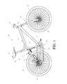
- Figure 1 is a side view of an embodiment of a bicycle frame.
- Figure 2 illustrates a bicycle suspension fork.
- Figure 3 is a cross section of a portion of the bicycle suspension fork of Figure 2 .
- Figure 4 is a cross section of a portion of a bicycle fork.
- Figure 5 is a cross section of a portion of a bicycle fork.
- Figure 6 is a cross section of a portion of a bicycle fork.
- Figure 7 is a cross section of a portion of a bicycle fork.
- Figure 8 is a cross section of a portion of a bicycle fork.
- Figure 1 illustrates a bicycle, and more particularly, an off-road bicycle or mountain bike 20.
- the term “longitudinal” refers to a direction, length or a location between the front and rear of the bicycle 20.
- the term “lateral” refers to a direction, length or location between the sides of the bicycle 20. Heights may be described as relative distances from a surface upon which the bicycle 20 is operated in a normal manner.
- the terms “above” or “below” generally apply to the bicycle as assembled, and being oriented as it would be normally ridden, or as it is depicted in any of the relevant figures.
- Front, rear, left, and right directions generally refer to those directions from the perspective of a rider normally seated on the bicycle 20.
- the mountain bike 20 includes a frame assembly 22, a front wheel 24 and rear wheel 26.
- the frame assembly 22 supports a seat assembly 28 at a location spaced rearward from a handlebar assembly 30.
- the handlebar assembly 30 is rotatably supported by the frame assembly 22 and is coupled to the front wheel 24 such that rotation of the handlebar 30 results in rotation of the front wheel 24 about a steering axis As of the mountain bike 20.
- the mountain bike 20 also includes a drive train 32 that is configured to allow a rider of the mountain bike 20 to supply power to one or both of the wheels 24, 26.
- the drive train 32 includes a pedal crank 34 that is coupled to the rear wheel 26 by a multispeed chain drive transmission 36.
- the multispeed chain drive transmission 36 may include one or more gears, or chain rings, coupled to the pedal crank 34 and one or more gears, or sprockets, coupled to the rear wheel 26.
- the chain rings and sprockets are coupled by an endless drive chain that is capable of transmitting torque from the pedal crank 34 to the rear wheel 26.
- One or more shifting mechanisms such as a derailleur, may be provided to shift the chain between the chain rings or sprockets.
- the shifting mechanism may be controlled by rider controls mounted on the handlebar assembly 30.
- the mountain bike 20 includes front and rear brake assemblies 38, 40 associated with the front and rear wheels 24, 26, respectively.
- the brake assemblies 38, 40 may be controllable by a rider of the mountain bike 20, typically via hand controls provided on the handlebar 30.
- the illustrated brake assemblies 38, 40 are disc brakes, other suitable types of brakes assemblies, such as rim brakes, for example, may also be used.
- the rear wheel 26 is supported for movement relative to at least a portion of the frame assembly 22.
- the frame assembly 22 includes a mainframe portion 42 and a subframe portion 44.
- the bicycle 20 also includes a shock absorber 46 as part of a rear suspension assembly 48 to influence movement of the subframe 44, and the rear wheel 26, relative to the mainframe 42.
- the subframe 44 is a multi-linkage arrangement that includes a plurality of interconnected linkage members.
- the bike 20 may be of a rigid frame design, or hardtail, in which no rear suspension assembly is provided.
- the mainframe 42 and subframe 44 may be of any suitable shape and may be constructed of any suitable material or combination of materials, as will be appreciated by one of skill in the art.
- the mountain bike 20 also incorporates a front suspension assembly 50 that movably supports the front wheel 24 relative to the mainframe 42 of the frame assembly 22.
- the front suspension assembly 50 as illustrated herein is a suspension fork 50 that is supported at its upper end by the mainframe 42 for rotation relative to the frame assembly 22 of the mountain bike 20.
- the suspension fork 50 rotatably supports the front wheel 24 at its lower end.
- the handlebar 30 is coupled to the suspension fork 50 such that rotation of the handlebar 30 causes rotation of the front suspension fork 50, and thus the front wheel 24, about the steering axis As.
- the present fork is described herein in the form of a front suspension fork for a mountain bike 20.
- the term “fork” is used in its ordinary meaning and includes various forms of a fork for a vehicle and, in particular, for a bicycle. Thus, the term “fork” can have one or more legs or struts.
- linkage-type front suspension assemblies are also intended to fall within the definition of a “fork.”
- certain features, aspects and advantages may be utilized in other vehicles, as well. For example, certain features, aspects and advantages may be utilized in other two-wheeled vehicles, such as motorcycles, for example.
- the fork may be of a rigid design in which no suspension assembly is provided.
- the suspension fork 50 is shown separated from the remainder of the mountain bike 20.
- the suspension fork 50 includes a first fork leg 52 and a second fork leg 54 that straddle the front wheel 24 of the mountain bike 20.
- the upper ends of the fork legs 52, 54 are coupled to a steer tube, or steerer 56 through a crown 58.
- the steer tube 56 is received within a head tube of the mainframe 42 of the bicycle frame assembly 22.
- each fork leg 52, 54 includes a wheel mount 90 which cooperate with one another to support the front wheel 24.
- the wheel mounts 90 are often referred to as dropouts because the mounts 90 often include a generally vertical recess that is open at its lower end. The recess permits an axle of the front wheel 24 to "drop out" of the lower end of the recess when the wheel retention mechanism is loosened.
- the wheel mounts 90 may be of any suitable construction to support an axle of the front wheel 24, including the through-axle type mounting arrangement in which the wheel mounts 90 completely surround the axle of the front wheel 24. Other suitable arrangements may also be used.
- the fork legs 52, 54 include an upper fork leg portion or stanchion tube 80, 84 ("upper fork leg or tube”) and a lower fork leg portion 82, 86 ("lower fork leg or tube”).
- the respective upper and lower fork legs are telescopically engaged with one another such that an overall length of the fork leg 52, 54 may vary.
- the crown 58 may interconnect the upper ends of the upper fork legs 80, 84.
- the lower fork legs 82, 86 maybe interconnected by an arch 88.
- the arch 88 preferably is integrally formed with the legs 82, 86. In one arrangement, the legs 82 and 86, the arch 88 and the wheel supports 90 are cast as a single piece. However, other suitable arrangements are possible as well.
- the crown 58 and the arch 88 resist twisting of the upper fork legs 80, 84 and lower fork legs 82, 86, respectively.
- the suspension fork 50 further can include a spring and/or a damper as is known in the art.
- the suspension fork 50 can include certain controls 78 to control certain characteristics of the suspension. These controls can include, rebound adjust, damping control, shock compression, lockout, air pressure, and other adjustments.
- the controls 78 can include adjustment knobs, levers, switches, dials, valves, etc.
- suspension systems may use air to create a spring force.
- This may be in addition to or instead of a mechanical spring, such as a metal coil spring.
- Air springs are generally the spring system of choice on mountain bikes due to the lighter weight (compared to coil or elastomer springs) as well as the broad range of rate adjustability achieved by simply changing the air pressure in the air spring chamber. This broad spring rate adjustability can also cause many set-up problems.
- a shock with an air spring design such as the suspension fork 50 shown in Figure 3
- the shock includes a first valve 60 (represented schematically) to allow air to be added or removed from the shock.
- the first valve 60 desirably is a Schrader valve, though other types of valves such as Presta can also be used.
- the shock may also include a cap 62 that can cover and seal the first valve 60 from dirt, grime, and undesired contact. The cap 62 can be removed to allow access to the first valve 60.
- Air can be released from the shock's air chamber 64 by simply depressing the internal valve body, the same as when releasing air from a bicycle or car tire. Air can be added to the air chamber 64 through a pump attached to the first valve 60.
- High pressure shock pumps available through shock and bike companies as an aftermarket purchase, are generally used to add air to shocks. Many of these pumps also include a button to allow the user to release or bleed off air. Whether air is released through a pump or solely through the valve, there is little control on the amount of air released. The control is solely by feel. The amount of air released is determined by how far the valve or button is depressed and for how long. In other words, the amount bled varies each time a bleed down is attempted.
- the shock absorber includes a metering mechanism to allow for the incremental release of air for the reduction of air pressure within the shock.
- the improved shock absorber can bleed down the air pressure of an air spring system in a controlled, precise way.
- the improved shock absorber can repeatably incrementally release air from the shock independent of the particular user.
- the shock absorber is shown with a first valve 60 that can communicate with a main air chamber 64.
- the first valve 60 can be a Schrader valve, or other known valves and can be used to add air to or release air from the main air chamber 64. In this way the shock absorber can become pressurized to act as an air spring.
- the illustrated first valve 60 is a Schrader valve that includes an outer valve housing 68 into which a valve core is threaded.
- the valve core is an internal valve body or poppet valve 61, which is assisted by a spring.
- a cap 62 can cover the first valve 60 to protect the valve as has been discussed.
- the shock can also include a secondary air chamber or a volume adjusted chamber 66.
- the secondary air chamber 66 can be pressurized with the main air chamber 64 but then later, if desired, sealed off from the main air chamber 64 and vented to the atmosphere. This can allow an incremental decrease in air and air pressure because desirably only the air in the secondary air chamber 66 is released.
- the size of the secondary air chamber 66 can be controlled so that only a desired amount of air is released.
- the secondary air chamber 66 can be configured or positioned in different ways than those illustrated herein while still providing the benefit of controlled incremental air or pressure release from the shock.
- the secondary air chamber 66 is positioned within the shock body 96 and further within the main air chamber 64.
- the secondary air chamber 66 can be made of one or more components.
- the secondary air chamber 66 can be defined in part by an annular generally cylindrical secondary air chamber housing 67.
- the secondary air chamber 66 can also include a generally annular cap 69.
- the annular generally cylindrical secondary air chamber housing 67 and the generally annular cap 69 can be connected in many manners, including, adhesive, welding, friction fit, etc. As shown, these components are connected by a friction fit and also include a seal 71. Additional seals 73, 75 can be used to ensure an air tight connection with the shock body 96 at the wall 98.
- the secondary air chamber 66 can be positioned outside of the main air chamber 64.
- the secondary air chamber 66 is shown in particular relation to the first valve 60, it will be understood that the secondary air chamber 66 can be located in other positions on the shock absorber as well.
- the secondary air chamber 66 makes up a portion of the total air spring volume.
- a second valve can be used to control the fluid connections to the secondary air chamber 66.
- the second valve can be formed by the outer valve housing 68 positioned within the shock body 96 in a shock body end cap.
- the shock body end cap forms a centrally protruding cylindrical wall 98 that extends into the shock body 96.
- the outer valve housing 68 is positioned within this cylindrical wall 98.
- the outer valve housing 68 serves also serves as the internal valve body of the second valve and the cylindrical wall 98 serves as the valve housing of the second valve.
- the outer valve housing 68 has a number of seals, including first seal 70, second seal 72, third seal 74, fourth seal 76, positioned around the outer valve housing 68 that can also engage the wall 98.
- the outer valve housing 68 can engage the wall 98 with one or more of the seals 70, 72, 74, 76 to open to close access into or from the outer valve housing 68 through the wall 98.
- the seals can be o-rings, or gaskets, or other types of seals.
- the wall 98 has a first passage 77 that can provide access into the main air chamber 64, and a second passage 79 that can provide access into the secondary air chamber 66.
- the outer valve housing 68 can also include one or more channels, including a first channel 81, a second channel 83, and a third channel 85, to provide access into or out from the outer valve housing.
- a rod 92 or other type of fastener can be used to connect the secondary air chamber 66 to the shock body 96, such as at the wall 98.
- all or part of the secondary air chamber 66 can be made integrally with the shock body 96.
- the outer valve housing 68 also is shown with a slot 94. The slot 94 cooperates with the rod 92 to allow the outer valve housing to move up and down but prevents the outer valve housing from rotating or from being advanced too far into the shock body 96.
- Figure 5 illustrates the fluid flow paths, represented by arrows, within the shock absorber when air is being added or released through the first valve 60.
- the valve body 61 is depressed, opening the valve 60 which allows air to communicate from outside of the shock to the main air chamber 64 or vice versa.
- the secondary air chamber 66 is also in fluid communication with both outside the shock and the main air chamber 64. Thus, the main air chamber 64 and the secondary air chamber 66 will be at the same pressure. If a shock pump is attached to the outer valve housing 68, air will be added to both the main air chamber 64 and the secondary air chamber 66.
- air is able to pass into the shock through the first valve 60 and then through the wall of the outer valve housing 68 and the wall 98 of the shock body 96 where it then enters either the main air chamber 64 or the secondary air chamber 66. Air can also pass from the secondary air chamber 66 to the main air chamber or vice versa, both ways passing through the walls of the outer valve housing 68 and the shock body 96.
- Figures 6-8 illustrate a method of reducing the air pressure within the shock in a controlled incremental manner.
- the cap 62 has been partially unscrewed from the outer valve housing 68.
- the cap 62 can be used as a button to press down on the outer valve housing 68.
- the cap 62 can be completely removed and the outer valve housing 68 can be advanced downwards directly by a user.
- Figure 6 shows the outer valve housing 68 before it has advanced downwards. It can be seen that though the first valve 60 is closed, the main air chamber 64 and the secondary air chamber 66 are still in fluid communication with one another. Thus, the main air chamber 64 and the secondary air chamber 66 will be at the same pressure.
- the cap 62 and the outer valve housing 68 are then returned to their initial position shown in Figure 6 .
- the secondary air chamber 66 is again brought into fluid communication with the main air chamber 64. Because the secondary air chamber 66 coming from the position in Figure 8 is at atmospheric pressure which is less than the pressure inside a pressurized shock, the combined main air chamber 64 and secondary air chamber 66 will now be at a lower pressure than before the procedure.
- a method of adjusting the air pressure within a shock can include one or more of the following steps: 1) connecting a pump to a first valve on a shock body, 2) injecting air from the pump into a main air chamber and a secondary air chamber within the shock, 3) removing the pump from the first valve, 4) actuating a second valve on the shock body by moving the second valve from an initial position to a second position, wherein the main air chamber and the secondary air chamber are in fluid communication in the initial position but are not in fluid communication in the second position, 5) releasing air from the secondary air chamber to reduce the pressure within the shock, the secondary air chamber being in fluid communication with the atmosphere but not the main air chamber, and 6) returning the second valve to the initial position and bringing the secondary chamber into fluid communication with the main air chamber.
- the steps of filling the shock with air from a pump are done previous to the adjusting process.
- the second valve can be a valve housing surrounding the first valve.
- a method of adjusting the air pressure within a shock can include one or more of the following steps: 1) depressing a valve housing and moving the valve housing from an initial position to a second position, the valve housing surrounding a valve on a interior surface, the valve configured to receive a pump for adding air to both a main air chamber and a secondary air chamber, the valve housing movable within a shock body, 2) releasing air from the secondary air chamber to reduce the pressure within the main air chamber, the air passing between an outer surface of the valve housing and the shock body while the valve housing is in the second position, the secondary air chamber being in fluid communication with the atmosphere but not the main air chamber, and 3) returning the valve housing to the initial position and bringing the secondary chamber into fluid communication with the main air chamber.
- the venting of air to the atmosphere releases only the air pressure of the secondary air chamber or volume adjusted chamber so that the drop in pressure is an exact amount each time the system is utilized.
- the second valve must return to the start position where the secondary air chamber is in communication with the main air chamber of the spring system, and then the steps repeated.
- the desired pressure drop with each actuation of the second valve can vary depending on the final application. For most mountain bike forks, the ideal pressure drop is in the range of about 3-5 psi. To achieve the desired pressure drop and to determine the size of the volume adjusted chamber many factors can be considered including total air volume of the air spring, the travel of the air spring, and typical starting air pressure.
- the improved shock absorber can provide a mechanism for bleeding down the air pressure of an air spring system in a controlled, precise way.
- Air springs are generally the spring system of choice on mountain bikes due to the lighter weight (compared to coil or elastomer springs) as well as the broad range of rate adjustability achieved by simply changing the air pressure in the air spring chamber. Though this broad spring rate adjustability can also cause many set-up problems, the improved shock absorber can allow the user to have more control to achieve the proper spring rate for the specific rider. This can be done in less time and generally eliminates or reduces the incidents of deflating the shock too much.
Landscapes
- Engineering & Computer Science (AREA)
- General Engineering & Computer Science (AREA)
- Mechanical Engineering (AREA)
- Axle Suspensions And Sidecars For Cycles (AREA)
Applications Claiming Priority (1)
| Application Number | Priority Date | Filing Date | Title |
|---|---|---|---|
| US13/243,216 US8740237B2 (en) | 2011-09-23 | 2011-09-23 | Bicycle with suspension |
Publications (2)
| Publication Number | Publication Date |
|---|---|
| EP2573420A2 true EP2573420A2 (fr) | 2013-03-27 |
| EP2573420A3 EP2573420A3 (fr) | 2017-12-27 |
Family
ID=46939575
Family Applications (1)
| Application Number | Title | Priority Date | Filing Date |
|---|---|---|---|
| EP12184196.9A Withdrawn EP2573420A3 (fr) | 2011-09-23 | 2012-09-13 | Bicyclette avec suspension |
Country Status (2)
| Country | Link |
|---|---|
| US (3) | US8740237B2 (fr) |
| EP (1) | EP2573420A3 (fr) |
Cited By (3)
| Publication number | Priority date | Publication date | Assignee | Title |
|---|---|---|---|---|
| EP3220003A1 (fr) * | 2013-08-01 | 2017-09-20 | Specialized Bicycle Components, Inc. | Ressort pneumatique de bicyclette |
| FR3093987A1 (fr) | 2019-03-22 | 2020-09-25 | Decathlon | Suspension réglable pour un vélo |
| FR3094056A1 (fr) | 2019-03-22 | 2020-09-25 | Decathlon | Suspension réglable comprenant un dispositif de distribution de fluide |
Families Citing this family (11)
| Publication number | Priority date | Publication date | Assignee | Title |
|---|---|---|---|---|
| US8740237B2 (en) | 2011-09-23 | 2014-06-03 | Specialized Bicycle Components, Inc. | Bicycle with suspension |
| JP5863540B2 (ja) * | 2012-04-02 | 2016-02-16 | 本田技研工業株式会社 | 自動二輪車及びフロントフォーク |
| US9168972B2 (en) * | 2014-01-02 | 2015-10-27 | Taiwan Hodaka Industrial Co., Ltd. | Control device for the rear shock absorber of a bicycle |
| US10029756B2 (en) | 2015-07-14 | 2018-07-24 | Duncan Bayard STOTHERS | Impact absorbing support for a wheel |
| US10942257B2 (en) | 2016-12-31 | 2021-03-09 | Innovusion Ireland Limited | 2D scanning high precision LiDAR using combination of rotating concave mirror and beam steering devices |
| US10753420B2 (en) * | 2018-04-16 | 2020-08-25 | Beijingwest Industries Co., Ltd. | Rotating three way valve for switchable air springs |
| US11614526B1 (en) | 2018-08-24 | 2023-03-28 | Innovusion, Inc. | Virtual windows for LIDAR safety systems and methods |
| CN109532377A (zh) * | 2018-11-12 | 2019-03-29 | 珠海格力电器股份有限公司 | 一种汽车控制方法、装置、存储介质及汽车 |
| WO2023019011A1 (fr) * | 2021-08-13 | 2023-02-16 | Stratum Reservoir (Us), Llc | Appareil et procédé de soupape d'échantillonnage de gaz |
| US12204033B2 (en) | 2022-03-25 | 2025-01-21 | Seyond, Inc. | Multimodal detection with integrated sensors |
| US20240308619A1 (en) * | 2023-03-13 | 2024-09-19 | Push Industries Incorporated | Fork Chassis Air Bleeder |
Family Cites Families (49)
| Publication number | Priority date | Publication date | Assignee | Title |
|---|---|---|---|---|
| GB1093327A (en) | 1965-05-14 | 1967-11-29 | Hoesch Ag | Improvements in or relating to suspension units for motor vehicles |
| GB1238508A (fr) | 1968-08-27 | 1971-07-07 | ||
| GB1371298A (en) | 1972-01-08 | 1974-10-23 | Stabilus Gmbh | Method and apparatus for the adjustment of the gas pressure in a compressed gas container |
| US4662616A (en) * | 1985-07-23 | 1987-05-05 | Rantom, Inc. | Combined check and exhaust valve for high pressure gas spring |
| US5244251A (en) | 1990-01-05 | 1993-09-14 | Ilan Bourla | Pneumatic seat for bicycle and method of manufacture |
| US5301973A (en) * | 1992-07-06 | 1994-04-12 | Rich Truchinski | Exterior adjustable suspension precompression fork cap mechanism for two wheeled vehicles |
| US5417446A (en) | 1994-09-08 | 1995-05-23 | Halson Designs, Inc. | Air damping for bicycle shock absorbing fork |
| GB2305991B (en) | 1995-10-09 | 1999-07-07 | Draftex Ind Ltd | Gas spring |
| DE19618055C1 (de) | 1996-05-06 | 1998-01-15 | Mannesmann Sachs Ag | Kolben-Zylinderaggregat mit wegabhängigem Dämpfkraftfeld |
| JPH10252801A (ja) | 1997-01-07 | 1998-09-22 | Showa:Kk | ガススプリング |
| US6105988A (en) | 1997-07-16 | 2000-08-22 | Rockshox, Inc. | Adjustable suspension system having positive and negative springs |
| DE19736074A1 (de) | 1997-08-20 | 1999-03-04 | Krupp Bilstein Gmbh | Gasfeder |
| DE19801055C1 (de) | 1998-01-14 | 1999-04-08 | Mannesmann Sachs Ag | Hydropneumatische Feder |
| US6135434A (en) | 1998-02-03 | 2000-10-24 | Fox Factory, Inc. | Shock absorber with positive and negative gas spring chambers |
| WO2000035686A2 (fr) | 1998-12-18 | 2000-06-22 | General Dynamics Ordnance And Tactical Systems, Inc. | Composants de suspension de motocyclette |
| JP2000266099A (ja) | 1999-03-16 | 2000-09-26 | Nissan Motor Co Ltd | 多段式ショックアブソーバ |
| US6328292B1 (en) | 2000-01-26 | 2001-12-11 | Scott Conrad Jarstad | Adjustable pneumatic spring |
| US6592136B2 (en) * | 2001-07-02 | 2003-07-15 | Fox Factory, Inc. | Bicycle fork cartridge assembly |
| US20040145101A1 (en) * | 2002-03-29 | 2004-07-29 | Olds Steven J. | Coil and air suspension system |
| US7703585B2 (en) | 2002-06-25 | 2010-04-27 | Fox Factory, Inc. | Integrated and self-contained suspension assembly having an on-the-fly adjustable air spring |
| US8464850B2 (en) | 2006-11-16 | 2013-06-18 | Fox Factory, Inc. | Gas spring curve control in an adjustable-volume gas-pressurized device |
| US20080296814A1 (en) | 2002-06-25 | 2008-12-04 | Joseph Franklin | Gas spring with travel control |
| US7963509B2 (en) | 2007-01-31 | 2011-06-21 | Fox Factory, Inc. | Travel control for a gas spring and gas spring having very short travel modes |
| US7284766B2 (en) | 2004-03-17 | 2007-10-23 | Dirk Temmerman | Air suspension system for motorcycles and bicycles |
| JP2006097880A (ja) | 2004-09-30 | 2006-04-13 | Hitachi Ltd | 油圧ダンパ |
| US7690666B2 (en) | 2005-08-18 | 2010-04-06 | Specialized Bicycle Components, Inc. | Position sensitive shock absorber |
| DE102005052148B4 (de) * | 2005-10-28 | 2009-02-12 | Continental Aktiengesellschaft | Pneumatische Niveauregelanlage |
| US7699146B1 (en) * | 2006-04-02 | 2010-04-20 | Fox Factory, Inc. | Suspension damper having inertia valve and user adjustable pressure-relief |
| US20090001684A1 (en) * | 2007-06-29 | 2009-01-01 | Specialized Bicycle Components, Inc. | Bicycle suspension assembly |
| DE102007056313A1 (de) | 2007-11-22 | 2009-05-28 | Canyon Bicycles Gmbh | Ventileinrichtung für ein Fahrrad-Federbein, Fahrrad-Federbein und Fahrrad-Dämpferpumpe sowie Verwendung einer Ventileinrichtung |
| US8894050B2 (en) | 2008-03-19 | 2014-11-25 | Fox Factory, Inc. | Methods and apparatus for suspending vehicles |
| US8869959B2 (en) | 2008-07-24 | 2014-10-28 | Fox Factory, Incorporated | Vehicle suspension damper |
| US20100244340A1 (en) | 2008-03-19 | 2010-09-30 | Wootten Dennis K | Methods and apparatus for combined variable damping and variable spring rate suspension |
| US9156325B2 (en) | 2008-03-19 | 2015-10-13 | Fox Factory, Inc. | Methods and apparatus for vehicle suspension having multiple gas volumes |
| US20090267316A1 (en) | 2008-04-25 | 2009-10-29 | Jose Gonzalez | Bicycle shock assemblies |
| US7900947B2 (en) * | 2008-07-31 | 2011-03-08 | Shimano Inc. | Bicycle suspension system |
| US7988173B2 (en) * | 2008-09-05 | 2011-08-02 | Sram, Llc | Bicycle suspension system |
| US20100109277A1 (en) | 2008-11-06 | 2010-05-06 | Furrer Fredrick J | Adjustable Monotube Shock Absorber |
| DE102008057268A1 (de) * | 2008-11-13 | 2010-05-20 | Dt Swiss Ag | Federgabel für ein Fahrrad |
| US9140325B2 (en) | 2009-03-19 | 2015-09-22 | Fox Factory, Inc. | Methods and apparatus for selective spring pre-load adjustment |
| US10036443B2 (en) | 2009-03-19 | 2018-07-31 | Fox Factory, Inc. | Methods and apparatus for suspension adjustment |
| US20120080279A1 (en) | 2009-03-19 | 2012-04-05 | Fox Factory, Inc. | Methods and apparatus for sag adjustment |
| US20100276906A1 (en) | 2009-05-04 | 2010-11-04 | Mario Galasso | Suspension system for a vehicle |
| US8936139B2 (en) | 2009-03-19 | 2015-01-20 | Fox Factory, Inc. | Methods and apparatus for suspension adjustment |
| US9056650B2 (en) * | 2009-06-15 | 2015-06-16 | Trek Bicycle Corporation | Bicycle shock assemblies with plunger operated valve arrangement |
| US8807300B2 (en) * | 2009-10-26 | 2014-08-19 | Fox Factory, Inc. | Methods and apparatus for managing pressurized gas in fluid dampers |
| US8480064B2 (en) * | 2010-07-09 | 2013-07-09 | Specialized Bicycle Components, Inc. | Bicycle with suspension |
| TWM404816U (en) | 2010-09-01 | 2011-06-01 | Kind Shock Hi Tech Co Ltd | Structure improvement for rear shock absorber |
| US8740237B2 (en) | 2011-09-23 | 2014-06-03 | Specialized Bicycle Components, Inc. | Bicycle with suspension |
-
2011
- 2011-09-23 US US13/243,216 patent/US8740237B2/en active Active
-
2012
- 2012-09-13 EP EP12184196.9A patent/EP2573420A3/fr not_active Withdrawn
-
2014
- 2014-05-09 US US14/274,461 patent/US9399496B2/en active Active
-
2016
- 2016-06-23 US US15/191,118 patent/US9821878B2/en active Active
Non-Patent Citations (1)
| Title |
|---|
| None |
Cited By (7)
| Publication number | Priority date | Publication date | Assignee | Title |
|---|---|---|---|---|
| EP3220003A1 (fr) * | 2013-08-01 | 2017-09-20 | Specialized Bicycle Components, Inc. | Ressort pneumatique de bicyclette |
| FR3093987A1 (fr) | 2019-03-22 | 2020-09-25 | Decathlon | Suspension réglable pour un vélo |
| FR3094056A1 (fr) | 2019-03-22 | 2020-09-25 | Decathlon | Suspension réglable comprenant un dispositif de distribution de fluide |
| WO2020193897A1 (fr) | 2019-03-22 | 2020-10-01 | Decathlon | Suspension reglable pour un velo |
| WO2020193895A1 (fr) | 2019-03-22 | 2020-10-01 | Decathlon | Suspension reglable comprenant un dispositif de distribution de fluide |
| US12173772B2 (en) | 2019-03-22 | 2024-12-24 | Decathlon | Adjustable suspension for a bicycle |
| US12172728B2 (en) | 2019-03-22 | 2024-12-24 | Decathlon | Adjustable suspension comprising a fluid distribution device |
Also Published As
| Publication number | Publication date |
|---|---|
| US20130075998A1 (en) | 2013-03-28 |
| US20140246118A1 (en) | 2014-09-04 |
| US20160297498A1 (en) | 2016-10-13 |
| US9821878B2 (en) | 2017-11-21 |
| US9399496B2 (en) | 2016-07-26 |
| US8740237B2 (en) | 2014-06-03 |
| EP2573420A3 (fr) | 2017-12-27 |
Similar Documents
| Publication | Publication Date | Title |
|---|---|---|
| US9821878B2 (en) | Bicycle with suspension | |
| US10161474B2 (en) | Bicycle with suspension | |
| EP2112401B1 (fr) | Ensembles d'amortisseurs de bicyclette | |
| US20090001684A1 (en) | Bicycle suspension assembly | |
| EP2364904B1 (fr) | Ensembles formant amortisseurs pneumatiques de bicyclette dotés d'une performance de suspension réglable | |
| TWI380929B (zh) | 自行車懸吊系統 | |
| US20110121525A1 (en) | Bicycle suspension-setting adjustor assembly | |
| AU2012227197B2 (en) | Bicycle with suspension | |
| CN120773859A (zh) | 用于自行车的前叉 |
Legal Events
| Date | Code | Title | Description |
|---|---|---|---|
| PUAI | Public reference made under article 153(3) epc to a published international application that has entered the european phase |
Free format text: ORIGINAL CODE: 0009012 |
|
| 17P | Request for examination filed |
Effective date: 20120913 |
|
| AK | Designated contracting states |
Kind code of ref document: A2 Designated state(s): AL AT BE BG CH CY CZ DE DK EE ES FI FR GB GR HR HU IE IS IT LI LT LU LV MC MK MT NL NO PL PT RO RS SE SI SK SM TR |
|
| AX | Request for extension of the european patent |
Extension state: BA ME |
|
| PUAL | Search report despatched |
Free format text: ORIGINAL CODE: 0009013 |
|
| AK | Designated contracting states |
Kind code of ref document: A3 Designated state(s): AL AT BE BG CH CY CZ DE DK EE ES FI FR GB GR HR HU IE IS IT LI LT LU LV MC MK MT NL NO PL PT RO RS SE SI SK SM TR |
|
| AX | Request for extension of the european patent |
Extension state: BA ME |
|
| RIC1 | Information provided on ipc code assigned before grant |
Ipc: F16F 9/02 20060101AFI20171123BHEP Ipc: B62K 25/08 20060101ALI20171123BHEP Ipc: F16F 9/43 20060101ALI20171123BHEP |
|
| STAA | Information on the status of an ep patent application or granted ep patent |
Free format text: STATUS: REQUEST FOR EXAMINATION WAS MADE |
|
| RBV | Designated contracting states (corrected) |
Designated state(s): AL AT BE BG CH CY CZ DE DK EE ES FI FR GB GR HR HU IE IS IT LI LT LU LV MC MK MT NL NO PL PT RO RS SE SI SK SM TR |
|
| RIC1 | Information provided on ipc code assigned before grant |
Ipc: B60G 17/056 20060101ALI20181221BHEP Ipc: B62K 25/08 20060101ALI20181221BHEP Ipc: B62K 3/00 20060101ALI20181221BHEP Ipc: F16F 9/02 20060101AFI20181221BHEP Ipc: F16F 9/43 20060101ALI20181221BHEP Ipc: B62K 25/04 20060101ALI20181221BHEP Ipc: B62K 25/06 20060101ALI20181221BHEP Ipc: B62K 25/28 20060101ALI20181221BHEP |
|
| GRAP | Despatch of communication of intention to grant a patent |
Free format text: ORIGINAL CODE: EPIDOSNIGR1 |
|
| STAA | Information on the status of an ep patent application or granted ep patent |
Free format text: STATUS: GRANT OF PATENT IS INTENDED |
|
| INTG | Intention to grant announced |
Effective date: 20190207 |
|
| RIN1 | Information on inventor provided before grant (corrected) |
Inventor name: LAMPMAN, BRIAN Inventor name: MCANDREWS, MICHAEL Inventor name: JANKURA, ROBB |
|
| STAA | Information on the status of an ep patent application or granted ep patent |
Free format text: STATUS: THE APPLICATION IS DEEMED TO BE WITHDRAWN |
|
| 18D | Application deemed to be withdrawn |
Effective date: 20190618 |