EP2573428B1 - Getriebeeinheit und Verfahren zum Steuern einer Schmiermittelpumpe für die Getriebeeinheit - Google Patents
Getriebeeinheit und Verfahren zum Steuern einer Schmiermittelpumpe für die Getriebeeinheit Download PDFInfo
- Publication number
- EP2573428B1 EP2573428B1 EP11182328.2A EP11182328A EP2573428B1 EP 2573428 B1 EP2573428 B1 EP 2573428B1 EP 11182328 A EP11182328 A EP 11182328A EP 2573428 B1 EP2573428 B1 EP 2573428B1
- Authority
- EP
- European Patent Office
- Prior art keywords
- lubrication pump
- limit
- temperature
- gear unit
- lubricating oil
- Prior art date
- Legal status (The legal status is an assumption and is not a legal conclusion. Google has not performed a legal analysis and makes no representation as to the accuracy of the status listed.)
- Active
Links
- 238000005461 lubrication Methods 0.000 title claims description 78
- 238000000034 method Methods 0.000 title claims description 39
- 239000010687 lubricating oil Substances 0.000 claims description 61
- 230000004044 response Effects 0.000 claims description 21
- 238000004590 computer program Methods 0.000 claims description 12
- 230000008859 change Effects 0.000 claims description 10
- 230000003247 decreasing effect Effects 0.000 claims description 2
- 230000008569 process Effects 0.000 description 13
- 239000003921 oil Substances 0.000 description 4
- 230000009471 action Effects 0.000 description 3
- 238000010792 warming Methods 0.000 description 3
- 230000001419 dependent effect Effects 0.000 description 2
- 230000006698 induction Effects 0.000 description 2
- 239000000314 lubricant Substances 0.000 description 2
- 230000003190 augmentative effect Effects 0.000 description 1
- 238000006243 chemical reaction Methods 0.000 description 1
- 238000010276 construction Methods 0.000 description 1
- 238000001816 cooling Methods 0.000 description 1
- 230000006870 function Effects 0.000 description 1
- 238000010438 heat treatment Methods 0.000 description 1
- 239000012535 impurity Substances 0.000 description 1
- 238000012544 monitoring process Methods 0.000 description 1
- 230000003068 static effect Effects 0.000 description 1
- 230000002123 temporal effect Effects 0.000 description 1
- XLYOFNOQVPJJNP-UHFFFAOYSA-N water Substances O XLYOFNOQVPJJNP-UHFFFAOYSA-N 0.000 description 1
Images

Classifications
-
- F—MECHANICAL ENGINEERING; LIGHTING; HEATING; WEAPONS; BLASTING
- F16—ENGINEERING ELEMENTS AND UNITS; GENERAL MEASURES FOR PRODUCING AND MAINTAINING EFFECTIVE FUNCTIONING OF MACHINES OR INSTALLATIONS; THERMAL INSULATION IN GENERAL
- F16H—GEARING
- F16H57/00—General details of gearing
- F16H57/02—Gearboxes; Mounting gearing therein
- F16H57/021—Shaft support structures, e.g. partition walls, bearing eyes, casing walls or covers with bearings
- F16H57/022—Adjustment of gear shafts or bearings
-
- F—MECHANICAL ENGINEERING; LIGHTING; HEATING; WEAPONS; BLASTING
- F16—ENGINEERING ELEMENTS AND UNITS; GENERAL MEASURES FOR PRODUCING AND MAINTAINING EFFECTIVE FUNCTIONING OF MACHINES OR INSTALLATIONS; THERMAL INSULATION IN GENERAL
- F16N—LUBRICATING
- F16N7/00—Arrangements for supplying oil or unspecified lubricant from a stationary reservoir or the equivalent in or on the machine or member to be lubricated
- F16N7/38—Arrangements for supplying oil or unspecified lubricant from a stationary reservoir or the equivalent in or on the machine or member to be lubricated with a separate pump; Central lubrication systems
- F16N7/385—Central lubrication systems
-
- F—MECHANICAL ENGINEERING; LIGHTING; HEATING; WEAPONS; BLASTING
- F16—ENGINEERING ELEMENTS AND UNITS; GENERAL MEASURES FOR PRODUCING AND MAINTAINING EFFECTIVE FUNCTIONING OF MACHINES OR INSTALLATIONS; THERMAL INSULATION IN GENERAL
- F16H—GEARING
- F16H57/00—General details of gearing
- F16H57/04—Features relating to lubrication or cooling or heating
- F16H57/0434—Features relating to lubrication or cooling or heating relating to lubrication supply, e.g. pumps; Pressure control
-
- F—MECHANICAL ENGINEERING; LIGHTING; HEATING; WEAPONS; BLASTING
- F16—ENGINEERING ELEMENTS AND UNITS; GENERAL MEASURES FOR PRODUCING AND MAINTAINING EFFECTIVE FUNCTIONING OF MACHINES OR INSTALLATIONS; THERMAL INSULATION IN GENERAL
- F16H—GEARING
- F16H59/00—Control inputs to control units of change-speed- or reversing-gearings for conveying rotary motion
- F16H59/68—Inputs being a function of gearing status
- F16H59/72—Inputs being a function of gearing status dependent on oil characteristics, e.g. temperature, viscosity
-
- F—MECHANICAL ENGINEERING; LIGHTING; HEATING; WEAPONS; BLASTING
- F16—ENGINEERING ELEMENTS AND UNITS; GENERAL MEASURES FOR PRODUCING AND MAINTAINING EFFECTIVE FUNCTIONING OF MACHINES OR INSTALLATIONS; THERMAL INSULATION IN GENERAL
- F16H—GEARING
- F16H61/00—Control functions within control units of change-speed- or reversing-gearings for conveying rotary motion ; Control of exclusively fluid gearing, friction gearing, gearings with endless flexible members or other particular types of gearing
- F16H61/0021—Generation or control of line pressure
- F16H61/0025—Supply of control fluid; Pumps therefor
- F16H61/0031—Supply of control fluid; Pumps therefor using auxiliary pumps, e.g. pump driven by a different power source than the engine
-
- F—MECHANICAL ENGINEERING; LIGHTING; HEATING; WEAPONS; BLASTING
- F04—POSITIVE - DISPLACEMENT MACHINES FOR LIQUIDS; PUMPS FOR LIQUIDS OR ELASTIC FLUIDS
- F04B—POSITIVE-DISPLACEMENT MACHINES FOR LIQUIDS; PUMPS
- F04B2203/00—Motor parameters
- F04B2203/02—Motor parameters of rotating electric motors
- F04B2203/0207—Torque
-
- F—MECHANICAL ENGINEERING; LIGHTING; HEATING; WEAPONS; BLASTING
- F04—POSITIVE - DISPLACEMENT MACHINES FOR LIQUIDS; PUMPS FOR LIQUIDS OR ELASTIC FLUIDS
- F04B—POSITIVE-DISPLACEMENT MACHINES FOR LIQUIDS; PUMPS
- F04B2203/00—Motor parameters
- F04B2203/02—Motor parameters of rotating electric motors
- F04B2203/0209—Rotational speed
-
- F—MECHANICAL ENGINEERING; LIGHTING; HEATING; WEAPONS; BLASTING
- F04—POSITIVE - DISPLACEMENT MACHINES FOR LIQUIDS; PUMPS FOR LIQUIDS OR ELASTIC FLUIDS
- F04B—POSITIVE-DISPLACEMENT MACHINES FOR LIQUIDS; PUMPS
- F04B2203/00—Motor parameters
- F04B2203/02—Motor parameters of rotating electric motors
- F04B2203/021—Lubricating-oil temperature
-
- F—MECHANICAL ENGINEERING; LIGHTING; HEATING; WEAPONS; BLASTING
- F16—ENGINEERING ELEMENTS AND UNITS; GENERAL MEASURES FOR PRODUCING AND MAINTAINING EFFECTIVE FUNCTIONING OF MACHINES OR INSTALLATIONS; THERMAL INSULATION IN GENERAL
- F16H—GEARING
- F16H2312/00—Driving activities
- F16H2312/14—Going to, or coming from standby operation, e.g. for engine start-stop operation at traffic lights
-
- F—MECHANICAL ENGINEERING; LIGHTING; HEATING; WEAPONS; BLASTING
- F16—ENGINEERING ELEMENTS AND UNITS; GENERAL MEASURES FOR PRODUCING AND MAINTAINING EFFECTIVE FUNCTIONING OF MACHINES OR INSTALLATIONS; THERMAL INSULATION IN GENERAL
- F16H—GEARING
- F16H57/00—General details of gearing
- F16H57/04—Features relating to lubrication or cooling or heating
- F16H57/0412—Cooling or heating; Control of temperature
- F16H57/0413—Controlled cooling or heating of lubricant; Temperature control therefor
-
- F—MECHANICAL ENGINEERING; LIGHTING; HEATING; WEAPONS; BLASTING
- F16—ENGINEERING ELEMENTS AND UNITS; GENERAL MEASURES FOR PRODUCING AND MAINTAINING EFFECTIVE FUNCTIONING OF MACHINES OR INSTALLATIONS; THERMAL INSULATION IN GENERAL
- F16N—LUBRICATING
- F16N2250/00—Measuring
- F16N2250/08—Temperature
Definitions
- the invention relates to a gear unit and to a method for controlling a lubrication pump of a gear unit. Furthermore, the invention relates to a computer program for controlling a lubrication pump of a gear unit.
- a lubrication system of a gear unit comprises typically a lubrication pump that is arranged to circulate lubricating oil through a gear stage or gear stages of the gear unit and through the bearings of the gear unit.
- the lubrication pump has to be designed and operated in way that the lubrication pump is not damaged even if the lubricating oil is cold and thereby its viscosity is relatively high.
- Publication US2011204633 describes a starting method for a rotating machine which includes a main shaft, a main bearing rotatably supporting the main shaft and a lubrication pump for circulating lubricant through the main bearing.
- the starting method includes steps of: rotating the main shaft to raise temperature of the main bearing in a state in which the lubrication pump is not operated; and operating the lubrication pump to start supplying the lubricant to the main bearing after the step of raising the temperature of the main bearing.
- gearwheel to refer to a cogged, rotating machine part.
- Two or more meshing gearwheels constitute a gear stage.
- gear refers in this document to a mechanical system having a first shaft and a second shaft, between which one or more gear stages provide speed and torque conversions and/or a change in a direction of a rotation axis.
- a gear unit comprises a gear proper and may comprise auxiliary augmenting systems, such as instrumentation, control, and lubrication arrangements.
- a new gear unit comprising:
- the present invention solves a technical problem which is present in many prior art gear units in which a fixed torque limit is used during a cold start process, and thereby the trade-off between the time required for the cold start process and the fault risk and wear of the lubrication pump is more inconvenient.
- the electrical device is further arranged to control the electrical motor so that the rotational speed of the lubrication pump is below a speed limit, and to change the speed limit in response to changes of the temperature signal.
- both the maximum allowable torque and the maximum allowable rotational speed are determined on the basis of the measured temperature of the lubricating oil. This arrangement makes it possible to protect the lubrication pump against mechanical faults during a cold start process in a way that unnecessarily strict torque and speed limitations, which would slow down the cold start process, can be avoided.
- the lubrication pump can be, for example but not necessarily, driven with an alternating current motor, e.g. an induction motor, fed with a static frequency converter.
- the torque limitation can be implemented with a current limitation and the speed limitation can be implemented with a frequency limitation.
- a new method for controlling a lubrication pump of a gear unit comprises:
- a new computer program for controlling a lubrication pump of a gear unit comprises computer executable instructions for controlling a programmable processor to:
- a computer program product according to the invention comprises a non-volatile computer readable medium, e.g. a compact disc ("CD”), encoded with a computer program according to the invention.
- a non-volatile computer readable medium e.g. a compact disc (“CD")
- FIG. 1 shows a schematic illustration of a gear unit 100 according to an advantageous, exemplifying embodiment of the invention.
- the gear unit comprises a first shaft 101 and a second shaft 102 for connecting to an external mechanical system.
- the external mechanical system may comprise, for example but not necessarily, a wind turbine that can be connected to the shaft 101 and a generator that can be connected to the shaft 102, i.e. the gear unit can be for example a gear unit suitable for a wind power application.
- the gear unit comprises at least one gear stage 103 between the shafts 101 and 102.
- the at least one gear stage may comprise, for example, one or more planet gear stages, one or more cylindrical gear stages and/or one or more conical gear stages, or a combination of gear stages of the kind mentioned above.
- the gear unit comprises a lubrication pump 104 for circulating lubricating oil through the at least one gear stage and bearings 109 of the gear unit.
- the lubrication pump can be, for example, a gear type pump.
- the gear unit comprises an oil tank 110 that constitutes a part of a circulation path of the lubricating oil. It is also possible that there is an oil sump 106 that constitutes, instead of or in addition to the oil tank 110, a reservoir for the lubricating oil.
- the gear unit comprises a temperature sensor 105 for measuring the temperature of the lubricating oil and supplying a temperature signal representative of the measured temperature.
- the temperature sensor is preferably arranged to measure the temperature of the lubricating oil from an inlet of the lubrication pump 104. However, it is also possible to measure the temperature from, for example, the oil tank 110. Furthermore, it is also possible to measure the temperature of the lubricating oil in an indirect way by measuring the temperature of the inlet tube of the lubrication pump or by measuring the temperature of the lubrication pump itself.
- the gear unit comprises an electrical motor 107 for driving the lubrication pump 104, and an electrical device 108 for energizing and controlling the electrical motor so that the torque directed to the lubrication pump is below a torque limit.
- the electrical device 108 is arranged to change the torque limit in response to changes of the temperature signal so that the torque limit is changed dynamically according to the measured temperature of the lubricating oil.
- the rotational speed of the lubrication pump depends on the torque-speed characteristics of the lubrication pump at the prevailing temperature and pressure of the lubricating oil being pumped.
- the rotational speed of the lubrication pump 104 is preferably limited to be below a speed limit.
- the electrical device 108 is arranged to increase the torque limit in response to an increase of the temperature of the lubricating oil when the temperature of the lubricating oil is below a point at which the lubrication ability of the lubricating oil is at its best, i.e. the increase of the lubrication ability due to the increase of the temperature is utilized by increasing the torque so as to shorten the cold start process.
- the electrical device 108 is arranged to change the speed limit in response to changes of the temperature signal. Hence, both the maximum allowable torque and the maximum allowable rotational speed can be changed dynamically according to the measured temperature of the lubricating oil.
- the electrical device 108 is arranged to increase the speed limit and decrease the torque limit in response to an increase of the temperature of the lubricating oil. Therefore, the upper limit of the mechanical power directed to the lubrication pump can be kept substantially constant when the lubricating oil is warmed up. The fact that there is an upper limit of the mechanical power can be utilized when dimensioning the electrical motor 107 and the electrical device 108.
- the temperature range of the lubricating oil is divided into a plurality of successive sub-ranges.
- the electrical device 108 is arranged to use a sub-range specific torque limit for each of the sub-ranges.
- the electrical device 108 is arranged to use a sub-range specific torque limit and also a sub-range specific speed limit for each of the sub-ranges.
- the successive sub-ranges can be for example: under -10°C, -10°C...+10°C, +10°C...+40°C, over +40°C.
- the electrical device 108 is arranged to activate an oil-heater element 112 for warming up the lubricating oil when the measured temperature of the lubricating oil is below a first pre-determined temperature limit, e.g. +40°C.
- the electrical device 108 is arranged to activate the oil-heater element 112 for warming up the lubricating oil and also a pump-heater element 113 for warming up the lubrication pump 104 when the measured temperature of the lubricating oil is below a second pre-determined temperature limit, e.g. -10°C, that is lower than the first temperature limit.
- a second pre-determined temperature limit e.g. -10°C
- the electrical device 108 is arranged to activate a blower 115 of an oil-cooler element 114 for cooling the lubricating oil when the measured temperature of the lubricating oil is above a third pre-determined temperature limit, e.g. +50°C, that is higher than the first and second temperature limits.
- a third pre-determined temperature limit e.g. +50°C
- the electrical motor 107 is an alternating current motor and the electrical device 108 comprises a frequency converter arranged to supply electrical energy to the electrical motor.
- the alternating current motor can be, for example, a three-phase induction motor.
- the electrical device 108 is supplied by a three-phase electrical power network 116.
- the frequency converter can be arranged to implement the limitation of the torque so that the amplitude or the effective value, e.g. the root mean square ("RMS"), of the current of the electrical motor is below a current limit and to implement the limitation of the rotational speed of the lubrication pump so that the frequency of the supply voltage of the electrical motor is below a frequency limit.
- RMS root mean square
- the frequency converter is arranged to apply a vector control principle in which both the amplitudes and the instantaneous phases of the voltages and currents of the electrical motor are controlled instead of controlling only the amplitudes and the frequency.
- the electrical motor 107 is a direct current ("DC") motor in which case the electrical device 108 may comprise e.g. a thyristor bridge for energizing and controlling the direct current motor.
- a gear unit comprises a filter element 117 for removing impurities from the lubricating oil.
- a gear unit comprises a sensor element 118 for monitoring the condition of the lubricating oil.
- the sensor element can be responsive, for example, to the purity degree of the lubricating oil and/or the water content of the lubricating oil.
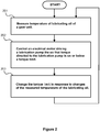
- Figure 2 shows a flow chart of a method according to an embodiment of the invention for controlling a lubrication pump of a gear unit.
- the method comprises:
- a method according to an embodiment of the invention comprises increasing the torque limit in response to an increase of the temperature of the lubricating oil when the temperature of the lubricating oil is below a point at which the lubrication ability of the lubricating oil is at its best, i.e. the increase of the lubrication ability due to the increase of the temperature is utilized by increasing the torque so as to shorten the cold start process.
- a method comprises controlling the electrical motor so that the torque directed to the lubrication pump is below the torque limit and the rotational speed of the lubrication pump is below a speed limit, and changing the torque limit and the speed limit in response to changes of the measured temperature of the lubricating oil.
- the speed limit is increased and the torque limit is decreased in response to an increase of the temperature of the lubricating oil. Therefore, the upper limit of the mechanical power directed to the lubrication pump can be kept substantially constant when the lubricating oil is warmed up.
- a range of the temperature of the lubricating oil is divided into a plurality of successive sub-ranges, and a sub-range specific torque limit is used for each of the sub-ranges.
- the range of the temperature of the lubricating oil is divided into the plurality of the successive sub-ranges, and the sub-range specific torque limit and a sub-range specific speed limit are used for each of the sub-ranges.
- the electrical motor is an alternating current motor and the torque is limited by limiting the amplitude or the effective value of the current of the electrical motor to be below a current limit, and the rotational speed of the lubrication pump is limited by limiting the frequency of the supply voltage of the electrical motor to be below a frequency limit.
- the temperature of the lubricating oil is measured from an inlet of the lubrication pump.
- a computer program comprises software modules for controlling a lubrication pump of a gear unit.
- the software modules comprise computer executable instructions for controlling a programmable processor to:
- the software modules can be, for example, subroutines and functions generated with a suitable programming language.
- a computer program product comprises a computer readable medium, e.g. a compact disc ("CD”), encoded with a computer program according to an embodiment of the invention.
- a computer readable medium e.g. a compact disc (“CD")
- a signal according to an embodiment of the invention is encoded to carry information defining a computer program according to an embodiment of the invention.
Landscapes
- Engineering & Computer Science (AREA)
- General Engineering & Computer Science (AREA)
- Mechanical Engineering (AREA)
- Oil, Petroleum & Natural Gas (AREA)
- General Details Of Gearings (AREA)
- Control Of Positive-Displacement Pumps (AREA)
- Lubricants (AREA)
Claims (15)
- Getriebeeinheit (100), umfassend:- eine erste Welle (101) und eine zweite Welle (102) zur Verbindung mit einem externen mechanischen System,- wenigstens eine Getriebestufe (103) zwischen der ersten und der zweiten Welle,- eine Schmiermittelpumpe (104) zum Zirkulieren von Schmieröl durch die wenigstens eine Getriebestufe und Lager (109) der Getriebeeinheit,- einen Temperatursensor (105) zum Messen einer Temperatur des Schmieröls und Bereitstellen eines diese anzeigenden Temperatursignals,- einen Elektromotor (107) zum Antreiben der Schmiermittelpumpe, und- eine elektrische Vorrichtung (108) zur Stromversorgung und zum Regeln/Steuern des Elektromotors, so dass ein Drehmoment, welches an die Schmiermittelpumpe gerichtet ist, unter einem Drehmomentgrenzwert liegt,
dadurch gekennzeichnet, dass die elektrische Vorrichtung dazu eingerichtet ist, den Drehmomentgrenzwert als Reaktion auf Änderungen des Temperatursignals zu ändern. - Getriebeeinheit nach Anspruch 1, wobei die elektrische Vorrichtung dazu eingerichtet ist, den Elektromotor zu regeln/steuern, so dass eine Umdrehungsgeschwindigkeit der Schmiermittelpumpe unter einem Geschwindigkeitgrenzwert liegt, und den Geschwindigkeitgrenzwert als Reaktion auf Änderungen des Temperatursignals zu ändern.
- Getriebeeinheit nach Anspruch 2, wobei die elektrische Vorrichtung dazu eingerichtet ist, als Reaktion auf einen Anstieg der Temperatur des Schmieröls, den Geschwindigkeitgrenzwert anzuheben und den Drehmomentgrenzwert zu senken.
- Getriebeeinheit nach einem der Ansprüche 1 - 3, wobei ein Bereich der Temperatur des Schmieröls eine Mehrzahl von aufeinanderfolgenden Unterbereichen umfasst und die elektrische Vorrichtung dazu eingerichtet ist, einen Unterbereich-spezifischen Drehmomentgrenzwert für jeden der Unterbereiche zu verwenden.
- Getriebeeinheit nach Anspruch 4, wobei die aufeinanderfolgenden Unterbereiche sind: unter -10°C, -10°C ... +10°C, + 10°C ... +40°C, über +40°C.
- Getriebeeinheit nach einem der Ansprüche 1 - 5, wobei der Elektromotor ein Wechselstrommotor ist und die elektrische Vorrichtung einen Frequenzkonverter umfasst, welcher dazu eingerichtet ist, elektrische Energie an den Elektromotor zu liefern.
- Getriebeeinheit nach Anspruch 6, wobei der Frequenzkonverter dazu eingerichtet ist, das Drehmoment zu begrenzen, so dass eine Amplitude eines Stroms des Elektromotors unter einem Stromgrenzwert liegt, und die Umdrehungsgeschwindigkeit der Schmiermittelpumpe zu begrenzen, so dass eine Frequenz einer Versorgungsspannung des elektrischen Motors unter einem Frequenzgrenzwert liegt.
- Getriebeeinheit nach einem der Ansprüche 1 - 7, wobei der Temperatursensor (105) dazu eingerichtet ist, die Temperatur des Schmieröls von einem Einlass der Schmiermittelpumpe zu messen.
- Verfahren zum Regeln/Steuern einer Schmiermittelpumpe einer Getriebeeinheit, wobei das Verfahren umfasst:- Messen (201) einer Temperatur eines Schmieröls, welches durch die Schmiermittelpumpe zirkuliert wird, und- Regeln/Steuern (202) eines Elektromotors, welcher die Schmiermittelpumpe antreibt, so dass ein Drehmoment, welches an die Schmiermittelpumpe gerichtet ist, unter einem Drehmomentgrenzwert liegt,
dadurch gekennzeichnet, dass das Verfahren Ändern (203) des Drehmomentgrenzwerts als Reaktion auf Änderungen der gemessenen Temperatur des Schmieröls umfasst. - Verfahren nach Anspruch 9, wobei das Verfahren Regeln/Steuern des Elektromotors, so dass eine Umdrehungsgeschwindigkeit der Schmiermittelpumpe unter einem Geschwindigkeitgrenzwert liegt, und Ändern des Geschwindigkeitgrenzwerts als Reaktion auf Änderungen der gemessenen Temperatur umfasst.
- Verfahren nach Anspruch 10, wobei als Reaktion auf eine Steigerung der Temperatur des Schmieröls der Geschwindigkeitgrenzwert angehoben wird und der Drehmomentgrenzwert gesenkt wird.
- Verfahren nach einem der Ansprüche 9 - 11, wobei ein Bereich der Temperatur des Schmieröls in eine Mehrzahl von aufeinanderfolgenden Unterbereichen unterteilt wird, und ein Unterbereich-spezifischer Drehmomentgrenzwert für jeden der Unterbereiche verwendet wird.
- Verfahren nach Anspruch 9, wobei der Elektromotor ein Wechselstrommotor ist und das Drehmoment durch Begrenzen einer Amplitude eines Stroms des Elektromotors darauf, unter einem Stromgrenzwert zu liegen, begrenzt wird, und eine Umdrehungsgeschwindigkeit der Schmiermittelpumpe durch Begrenzen einer Frequenz einer Versorgungsspannung des Elektromotors darauf, unter einem Frequenzgrenzwert zu liegen, begrenzt wird.
- Verfahren nach einem der Ansprüche 9 - 13, wobei die Temperatur des Schmieröls von einem Einlass der Schmiermittelpumpe gemessen wird.
- Computerprogramm zum Regeln/Steuern einer Schmiermittelpumpe einer Getriebeeinheit, wobei das Computerprogramm computer-ausführbare Anweisungen zum Regeln/Steuern eines programmierbaren Prozessors umfasst, um einen Drehmomentgrenzwert an ein elektrisches System zu liefern, welches die Schmiermittelpumpe antreibt, wobei der Drehmomentgrenzwert das maximal zulässige Drehmoment anzeigt, welches an die Schmiermittelpumpe gerichtet ist, dadurch gekennzeichnet, dass das Computerprogramm ferner computer-ausführbare Anweisungen zum Regeln/Steuern des programmierbaren Prozessors umfasst, um den Drehmomentgrenzwert als Reaktion auf Änderungen eines Signals, welches eine gemessene Temperatur eines Schmieröls anzeigt, zu ändern.
Priority Applications (8)
| Application Number | Priority Date | Filing Date | Title |
|---|---|---|---|
| EP11182328.2A EP2573428B1 (de) | 2011-09-22 | 2011-09-22 | Getriebeeinheit und Verfahren zum Steuern einer Schmiermittelpumpe für die Getriebeeinheit |
| DK11182328.2T DK2573428T3 (en) | 2011-09-22 | 2011-09-22 | Gear unit and method for controlling a gear unit lubrication pump |
| ES11182328.2T ES2620265T3 (es) | 2011-09-22 | 2011-09-22 | Unidad de engranaje y método para controlar una bomba de lubricación de una unidad de engranaje |
| CA2790510A CA2790510C (en) | 2011-09-22 | 2012-09-20 | A gear unit and a method for controlling a lubrication pump of a gear unit |
| CN201210449153.5A CN103047399B (zh) | 2011-09-22 | 2012-09-21 | 齿轮单元以及用于控制齿轮单元的润滑泵的方法 |
| US13/624,595 US9618154B2 (en) | 2011-09-22 | 2012-09-21 | Gear unit and a method for controlling a lubrication pump of a gear unit |
| BR102012024124-2A BR102012024124B1 (pt) | 2011-09-22 | 2012-09-24 | Unidade de engrenagem e um método para controle de uma bomba de lubrificação de uma unidade de engrenagem |
| KR1020120106129A KR101890895B1 (ko) | 2011-09-22 | 2012-09-24 | 기어유닛과 기어유닛의 윤활펌프를 제어하는 방법 |
Applications Claiming Priority (1)
| Application Number | Priority Date | Filing Date | Title |
|---|---|---|---|
| EP11182328.2A EP2573428B1 (de) | 2011-09-22 | 2011-09-22 | Getriebeeinheit und Verfahren zum Steuern einer Schmiermittelpumpe für die Getriebeeinheit |
Publications (2)
| Publication Number | Publication Date |
|---|---|
| EP2573428A1 EP2573428A1 (de) | 2013-03-27 |
| EP2573428B1 true EP2573428B1 (de) | 2016-12-28 |
Family
ID=44759493
Family Applications (1)
| Application Number | Title | Priority Date | Filing Date |
|---|---|---|---|
| EP11182328.2A Active EP2573428B1 (de) | 2011-09-22 | 2011-09-22 | Getriebeeinheit und Verfahren zum Steuern einer Schmiermittelpumpe für die Getriebeeinheit |
Country Status (8)
| Country | Link |
|---|---|
| US (1) | US9618154B2 (de) |
| EP (1) | EP2573428B1 (de) |
| KR (1) | KR101890895B1 (de) |
| CN (1) | CN103047399B (de) |
| BR (1) | BR102012024124B1 (de) |
| CA (1) | CA2790510C (de) |
| DK (1) | DK2573428T3 (de) |
| ES (1) | ES2620265T3 (de) |
Families Citing this family (25)
| Publication number | Priority date | Publication date | Assignee | Title |
|---|---|---|---|---|
| US20130288843A1 (en) * | 2010-10-15 | 2013-10-31 | Vestas Wind Systems A/S | Machine system having a lubrication system |
| ES2479692T3 (es) * | 2011-09-22 | 2014-07-24 | Moventas Gears Oy | Un procedimiento para controlar la lubricación de una transmisión y una transmisión |
| ES2709485T3 (es) * | 2011-09-22 | 2019-04-16 | Moventas Gears Oy | Un método para controlar la lubricación de una unidad de engranaje y una unidad de engranaje |
| US8869940B2 (en) * | 2012-01-17 | 2014-10-28 | General Electric Company | Dual temperature oil control system and method for a wind turbine gearbox |
| DE102013203263A1 (de) * | 2013-02-27 | 2014-08-28 | Skf Lubrication Systems Germany Ag | Vorrichtung zur Schmierstoffzufuhr zu einer Schmierstelle in einer Maschine |
| CN103307434A (zh) * | 2013-06-09 | 2013-09-18 | 安徽永杰铜业有限公司 | 一种铜带轧机齿轮箱润滑系统压力调节装置 |
| CN103604032B (zh) * | 2013-10-21 | 2019-10-25 | 启东中冶润滑液压设备有限公司 | 尼龙齿轮润滑装置 |
| CN103498913B (zh) * | 2013-10-23 | 2015-12-09 | 大连华锐重工集团股份有限公司 | 适用于极端工况的风电齿轮箱润滑系统 |
| ES2645649T3 (es) | 2014-05-20 | 2017-12-07 | Moventas Gears Oy | Una unidad de engranajes y un método para calentar aceite lubricante de una unidad de engranajes |
| GB201409180D0 (en) * | 2014-05-23 | 2014-07-09 | Qinetiq Ltd | Improvements to oil pumps for motor vehicles |
| CN104197180A (zh) * | 2014-08-05 | 2014-12-10 | 蔡宏磊 | 一种润滑回油的温度控制装置 |
| CN104601050B (zh) * | 2014-12-24 | 2017-10-31 | 大连尚能科技发展有限公司 | 一种油泵电机的调速方法 |
| CN108287582A (zh) * | 2018-03-29 | 2018-07-17 | 湖北松滋松川矿山机械有限公司 | 一种用于大型振动筛的状态监测控制系统 |
| CN110553027A (zh) * | 2018-06-01 | 2019-12-10 | 中国船舶重工集团海装风电股份有限公司 | 齿轮箱冷却润滑系统及具有该系统的风力发电机组 |
| FR3093139B1 (fr) * | 2019-02-21 | 2021-01-22 | Renault Sas | Procede de controle du demarrage d’une pompe a huile |
| CN110333674A (zh) * | 2019-06-22 | 2019-10-15 | 郑州盛川科技有限公司 | 一种润滑系统闭环控制技术及实施方案 |
| CN111412371A (zh) * | 2019-07-02 | 2020-07-14 | 中国电力工程顾问集团华北电力设计院有限公司 | 由永磁无刷电动机与直流电动机组成的润滑油供油系统 |
| DE102019214650B3 (de) * | 2019-09-25 | 2020-12-10 | Hanon Systems Efp Deutschland Gmbh | Steuereinheit zur Druckregelung |
| CN114753999A (zh) * | 2022-03-10 | 2022-07-15 | 烟台杰瑞石油装备技术有限公司 | 润滑系统 |
| CN115885119A (zh) * | 2020-12-30 | 2023-03-31 | 华为数字能源技术有限公司 | 一种控制方法和装置 |
| CN113250918A (zh) * | 2021-06-07 | 2021-08-13 | 天津瑞能电气有限公司 | 一种风力发电机组齿轮箱维护保养装置 |
| CN113404779B (zh) * | 2021-08-18 | 2021-11-23 | 河南卫华重型机械股份有限公司 | 一种起重机行走车轮的全自动监测控制集中润滑系统 |
| EP4226824A1 (de) * | 2022-02-14 | 2023-08-16 | Vorwerk & Co. Interholding GmbH | Sauggerät sowie verfahren zum betrieb eines sauggerätes |
| CN115789233B (zh) * | 2023-02-08 | 2023-05-02 | 南京讯联液压技术股份有限公司 | 一种风力发电齿轮箱润滑伺服控制系统 |
| CN117366445A (zh) * | 2023-08-17 | 2024-01-09 | 东风汽车集团股份有限公司 | 一种润滑冷却系统及其控制方法 |
Family Cites Families (23)
| Publication number | Priority date | Publication date | Assignee | Title |
|---|---|---|---|---|
| JPS58157385A (ja) * | 1982-03-12 | 1983-09-19 | Fanuc Ltd | 交流モ−タの駆動方式 |
| US5310020A (en) * | 1993-06-09 | 1994-05-10 | Ingersoll-Rand Company | Self contained lubricating oil system for a centrifugal compressor |
| JP3329417B2 (ja) * | 1994-09-21 | 2002-09-30 | 株式会社フジユニバンス | トランスファ装置の潤滑構造 |
| JPH08251868A (ja) * | 1995-03-06 | 1996-09-27 | Komatsu Ltd | 電気油圧ハイブリッドモータ |
| JP3168951B2 (ja) * | 1997-09-01 | 2001-05-21 | 日産自動車株式会社 | 無段変速機の変速制御装置 |
| JP3383754B2 (ja) * | 1997-09-29 | 2003-03-04 | 日立建機株式会社 | 油圧建設機械の油圧ポンプのトルク制御装置 |
| DE10316515B4 (de) * | 2003-04-09 | 2005-04-28 | Prec Drilling Tech Serv Group | Verfahren und Vorrichtung zur Erzeugung von in einem Bohrloch übertragbaren Signalen |
| FI20040351L (fi) * | 2004-03-04 | 2005-09-05 | Abb Oy | Mittausmenetelmä ja -järjestely |
| JP3997227B2 (ja) * | 2004-12-02 | 2007-10-24 | 本田技研工業株式会社 | 油圧供給装置 |
| JP4614811B2 (ja) * | 2005-04-04 | 2011-01-19 | トヨタ自動車株式会社 | 駆動装置およびこれを搭載する自動車並びに駆動装置の制御方法 |
| JP4380636B2 (ja) * | 2006-01-24 | 2009-12-09 | トヨタ自動車株式会社 | 電動車両のオイルポンプ制御装置およびそれを搭載する電動車両 |
| US7508149B2 (en) * | 2007-06-07 | 2009-03-24 | Gm Global Technology Operations, Inc. | Oil pump systems and methods for preventing torque overload in motors of oil pump systems |
| WO2009037996A1 (en) * | 2007-09-21 | 2009-03-26 | Toyota Jidosha Kabushiki Kaisha | Control device for vehicular hydraulic control circuit |
| US8672642B2 (en) * | 2008-06-29 | 2014-03-18 | Bristol Compressors International, Inc. | System and method for starting a compressor |
| KR101173050B1 (ko) * | 2009-12-04 | 2012-08-13 | 기아자동차주식회사 | 전동식 오일펌프의 구동 제어 장치 및 방법 |
| CN201575285U (zh) * | 2009-12-10 | 2010-09-08 | 天津钢管集团股份有限公司 | 大型减速机稀油润滑系统 |
| AU2010204474B9 (en) * | 2010-02-19 | 2012-09-20 | Mitsubishi Heavy Industries, Ltd. | Starting method for rotating machine and starting method for wind turbine generator |
| JP5416060B2 (ja) * | 2010-09-06 | 2014-02-12 | 日立オートモティブシステムズ株式会社 | 車両用電動オイルポンプの制御装置 |
| JP5134663B2 (ja) * | 2010-09-10 | 2013-01-30 | ジヤトコ株式会社 | 変速機のオイル供給装置 |
| JP5193259B2 (ja) * | 2010-09-14 | 2013-05-08 | 株式会社日立カーエンジニアリング | 電動オイルポンプ用モータ制御装置及び制御方法 |
| CN201810502U (zh) * | 2010-10-22 | 2011-04-27 | 大连华锐股份有限公司 | 风力发电机组齿轮箱润滑系统 |
| US9022177B2 (en) * | 2010-11-29 | 2015-05-05 | Lincoln Industrial Corporation | Pump having stepper motor and overdrive control |
| JP2012207637A (ja) * | 2011-03-30 | 2012-10-25 | Hitachi Automotive Systems Ltd | 電動オイルポンプ |
-
2011
- 2011-09-22 EP EP11182328.2A patent/EP2573428B1/de active Active
- 2011-09-22 DK DK11182328.2T patent/DK2573428T3/en active
- 2011-09-22 ES ES11182328.2T patent/ES2620265T3/es active Active
-
2012
- 2012-09-20 CA CA2790510A patent/CA2790510C/en active Active
- 2012-09-21 CN CN201210449153.5A patent/CN103047399B/zh active Active
- 2012-09-21 US US13/624,595 patent/US9618154B2/en active Active
- 2012-09-24 KR KR1020120106129A patent/KR101890895B1/ko not_active Expired - Fee Related
- 2012-09-24 BR BR102012024124-2A patent/BR102012024124B1/pt not_active IP Right Cessation
Non-Patent Citations (1)
| Title |
|---|
| None * |
Also Published As
| Publication number | Publication date |
|---|---|
| EP2573428A1 (de) | 2013-03-27 |
| US9618154B2 (en) | 2017-04-11 |
| BR102012024124B1 (pt) | 2022-03-08 |
| CN103047399B (zh) | 2016-08-24 |
| KR101890895B1 (ko) | 2018-08-22 |
| BR102012024124A8 (pt) | 2016-04-05 |
| CA2790510A1 (en) | 2013-03-22 |
| US20130075198A1 (en) | 2013-03-28 |
| CN103047399A (zh) | 2013-04-17 |
| CA2790510C (en) | 2019-10-29 |
| DK2573428T3 (en) | 2017-04-03 |
| ES2620265T3 (es) | 2017-06-28 |
| KR20130032289A (ko) | 2013-04-01 |
| BR102012024124A2 (pt) | 2014-12-09 |
Similar Documents
| Publication | Publication Date | Title |
|---|---|---|
| EP2573428B1 (de) | Getriebeeinheit und Verfahren zum Steuern einer Schmiermittelpumpe für die Getriebeeinheit | |
| CN102725522B (zh) | 旋转机械的起动方法及风力发电装置的起动方法 | |
| EP2573388A1 (de) | Verfahren zur Steuerung der Schmierung einer Getriebeeinheit und Getriebeeinheit | |
| US10309518B2 (en) | Gear unit and a method for heating lubricant oil of a gear unit | |
| JPWO2010001479A1 (ja) | 風力発電装置 | |
| CN105089934B (zh) | 用于操作风力涡轮机的方法 | |
| US11988211B2 (en) | Vacuum pump | |
| SE0950602A1 (sv) | Kontrollsystem för vindturbin | |
| EP2652322B1 (de) | Windturbine und verfahren zum betrieb einer windturbine | |
| KR20110041858A (ko) | 풍력 발전기 윤활유 강제 순환 장치 | |
| HK1182754B (en) | A gear unit and a method for controlling a lubrication pump of a gear unit | |
| HK1182754A (en) | A gear unit and a method for controlling a lubrication pump of a gear unit | |
| Rajora et al. | Effect of lube oil temperature on turbine shaft vibration | |
| JP2012200820A (ja) | スピンドル制御装置及びスピンドル制御方法 | |
| CN104421215A (zh) | 转速可变的流体冷却过滤装置 | |
| CN102270002B (zh) | 能够控制电主轴润滑液粘度的系统及其方法 | |
| KR101265435B1 (ko) | 회전 기계의 기동 방법 및 풍력 발전 장치의 기동 방법 | |
| EP2889516B1 (de) | Hydraulische Übertragung und Stromerzeugungsvorrichtung mit erneuerbarer Energie | |
| HK1179321A (en) | A method for controlling lubrication of a gear unit and a gear unit | |
| HK1179321B (en) | A method for controlling lubrication of a gear unit and a gear unit |
Legal Events
| Date | Code | Title | Description |
|---|---|---|---|
| PUAI | Public reference made under article 153(3) epc to a published international application that has entered the european phase |
Free format text: ORIGINAL CODE: 0009012 |
|
| AK | Designated contracting states |
Kind code of ref document: A1 Designated state(s): AL AT BE BG CH CY CZ DE DK EE ES FI FR GB GR HR HU IE IS IT LI LT LU LV MC MK MT NL NO PL PT RO RS SE SI SK SM TR |
|
| AX | Request for extension of the european patent |
Extension state: BA ME |
|
| 17P | Request for examination filed |
Effective date: 20130903 |
|
| RBV | Designated contracting states (corrected) |
Designated state(s): AL AT BE BG CH CY CZ DE DK EE ES FI FR GB GR HR HU IE IS IT LI LT LU LV MC MK MT NL NO PL PT RO RS SE SI SK SM TR |
|
| REG | Reference to a national code |
Ref country code: HK Ref legal event code: DE Ref document number: 1182754 Country of ref document: HK |
|
| 17Q | First examination report despatched |
Effective date: 20150113 |
|
| RIC1 | Information provided on ipc code assigned before grant |
Ipc: F16N 7/38 20060101ALI20160616BHEP Ipc: F16H 57/04 20060101AFI20160616BHEP Ipc: F16N 39/04 20060101ALI20160616BHEP |
|
| GRAP | Despatch of communication of intention to grant a patent |
Free format text: ORIGINAL CODE: EPIDOSNIGR1 |
|
| INTG | Intention to grant announced |
Effective date: 20160804 |
|
| GRAS | Grant fee paid |
Free format text: ORIGINAL CODE: EPIDOSNIGR3 |
|
| GRAA | (expected) grant |
Free format text: ORIGINAL CODE: 0009210 |
|
| AK | Designated contracting states |
Kind code of ref document: B1 Designated state(s): AL AT BE BG CH CY CZ DE DK EE ES FI FR GB GR HR HU IE IS IT LI LT LU LV MC MK MT NL NO PL PT RO RS SE SI SK SM TR |
|
| REG | Reference to a national code |
Ref country code: GB Ref legal event code: FG4D |
|
| REG | Reference to a national code |
Ref country code: CH Ref legal event code: EP |
|
| REG | Reference to a national code |
Ref country code: AT Ref legal event code: REF Ref document number: 857596 Country of ref document: AT Kind code of ref document: T Effective date: 20170115 |
|
| REG | Reference to a national code |
Ref country code: IE Ref legal event code: FG4D |
|
| REG | Reference to a national code |
Ref country code: DE Ref legal event code: R096 Ref document number: 602011033787 Country of ref document: DE |
|
| PG25 | Lapsed in a contracting state [announced via postgrant information from national office to epo] |
Ref country code: LV Free format text: LAPSE BECAUSE OF FAILURE TO SUBMIT A TRANSLATION OF THE DESCRIPTION OR TO PAY THE FEE WITHIN THE PRESCRIBED TIME-LIMIT Effective date: 20161228 |
|
| REG | Reference to a national code |
Ref country code: DK Ref legal event code: T3 Effective date: 20170328 |
|
| REG | Reference to a national code |
Ref country code: LT Ref legal event code: MG4D |
|
| PG25 | Lapsed in a contracting state [announced via postgrant information from national office to epo] |
Ref country code: NO Free format text: LAPSE BECAUSE OF FAILURE TO SUBMIT A TRANSLATION OF THE DESCRIPTION OR TO PAY THE FEE WITHIN THE PRESCRIBED TIME-LIMIT Effective date: 20170328 Ref country code: LT Free format text: LAPSE BECAUSE OF FAILURE TO SUBMIT A TRANSLATION OF THE DESCRIPTION OR TO PAY THE FEE WITHIN THE PRESCRIBED TIME-LIMIT Effective date: 20161228 Ref country code: SE Free format text: LAPSE BECAUSE OF FAILURE TO SUBMIT A TRANSLATION OF THE DESCRIPTION OR TO PAY THE FEE WITHIN THE PRESCRIBED TIME-LIMIT Effective date: 20161228 Ref country code: GR Free format text: LAPSE BECAUSE OF FAILURE TO SUBMIT A TRANSLATION OF THE DESCRIPTION OR TO PAY THE FEE WITHIN THE PRESCRIBED TIME-LIMIT Effective date: 20170329 |
|
| REG | Reference to a national code |
Ref country code: NL Ref legal event code: MP Effective date: 20161228 |
|
| REG | Reference to a national code |
Ref country code: AT Ref legal event code: MK05 Ref document number: 857596 Country of ref document: AT Kind code of ref document: T Effective date: 20161228 |
|
| PG25 | Lapsed in a contracting state [announced via postgrant information from national office to epo] |
Ref country code: HR Free format text: LAPSE BECAUSE OF FAILURE TO SUBMIT A TRANSLATION OF THE DESCRIPTION OR TO PAY THE FEE WITHIN THE PRESCRIBED TIME-LIMIT Effective date: 20161228 Ref country code: RS Free format text: LAPSE BECAUSE OF FAILURE TO SUBMIT A TRANSLATION OF THE DESCRIPTION OR TO PAY THE FEE WITHIN THE PRESCRIBED TIME-LIMIT Effective date: 20161228 |
|
| REG | Reference to a national code |
Ref country code: ES Ref legal event code: FG2A Ref document number: 2620265 Country of ref document: ES Kind code of ref document: T3 Effective date: 20170628 |
|
| PG25 | Lapsed in a contracting state [announced via postgrant information from national office to epo] |
Ref country code: NL Free format text: LAPSE BECAUSE OF FAILURE TO SUBMIT A TRANSLATION OF THE DESCRIPTION OR TO PAY THE FEE WITHIN THE PRESCRIBED TIME-LIMIT Effective date: 20161228 |
|
| PG25 | Lapsed in a contracting state [announced via postgrant information from national office to epo] |
Ref country code: SK Free format text: LAPSE BECAUSE OF FAILURE TO SUBMIT A TRANSLATION OF THE DESCRIPTION OR TO PAY THE FEE WITHIN THE PRESCRIBED TIME-LIMIT Effective date: 20161228 Ref country code: RO Free format text: LAPSE BECAUSE OF FAILURE TO SUBMIT A TRANSLATION OF THE DESCRIPTION OR TO PAY THE FEE WITHIN THE PRESCRIBED TIME-LIMIT Effective date: 20161228 Ref country code: EE Free format text: LAPSE BECAUSE OF FAILURE TO SUBMIT A TRANSLATION OF THE DESCRIPTION OR TO PAY THE FEE WITHIN THE PRESCRIBED TIME-LIMIT Effective date: 20161228 Ref country code: IS Free format text: LAPSE BECAUSE OF FAILURE TO SUBMIT A TRANSLATION OF THE DESCRIPTION OR TO PAY THE FEE WITHIN THE PRESCRIBED TIME-LIMIT Effective date: 20170428 |
|
| PG25 | Lapsed in a contracting state [announced via postgrant information from national office to epo] |
Ref country code: PT Free format text: LAPSE BECAUSE OF FAILURE TO SUBMIT A TRANSLATION OF THE DESCRIPTION OR TO PAY THE FEE WITHIN THE PRESCRIBED TIME-LIMIT Effective date: 20170428 Ref country code: SM Free format text: LAPSE BECAUSE OF FAILURE TO SUBMIT A TRANSLATION OF THE DESCRIPTION OR TO PAY THE FEE WITHIN THE PRESCRIBED TIME-LIMIT Effective date: 20161228 Ref country code: PL Free format text: LAPSE BECAUSE OF FAILURE TO SUBMIT A TRANSLATION OF THE DESCRIPTION OR TO PAY THE FEE WITHIN THE PRESCRIBED TIME-LIMIT Effective date: 20161228 Ref country code: AT Free format text: LAPSE BECAUSE OF FAILURE TO SUBMIT A TRANSLATION OF THE DESCRIPTION OR TO PAY THE FEE WITHIN THE PRESCRIBED TIME-LIMIT Effective date: 20161228 Ref country code: BG Free format text: LAPSE BECAUSE OF FAILURE TO SUBMIT A TRANSLATION OF THE DESCRIPTION OR TO PAY THE FEE WITHIN THE PRESCRIBED TIME-LIMIT Effective date: 20170328 |
|
| REG | Reference to a national code |
Ref country code: FR Ref legal event code: PLFP Year of fee payment: 7 |
|
| REG | Reference to a national code |
Ref country code: DE Ref legal event code: R097 Ref document number: 602011033787 Country of ref document: DE |
|
| REG | Reference to a national code |
Ref country code: HK Ref legal event code: GR Ref document number: 1182754 Country of ref document: HK |
|
| PLBE | No opposition filed within time limit |
Free format text: ORIGINAL CODE: 0009261 |
|
| STAA | Information on the status of an ep patent application or granted ep patent |
Free format text: STATUS: NO OPPOSITION FILED WITHIN TIME LIMIT |
|
| 26N | No opposition filed |
Effective date: 20170929 |
|
| PG25 | Lapsed in a contracting state [announced via postgrant information from national office to epo] |
Ref country code: SI Free format text: LAPSE BECAUSE OF FAILURE TO SUBMIT A TRANSLATION OF THE DESCRIPTION OR TO PAY THE FEE WITHIN THE PRESCRIBED TIME-LIMIT Effective date: 20161228 |
|
| REG | Reference to a national code |
Ref country code: CH Ref legal event code: PL |
|
| PG25 | Lapsed in a contracting state [announced via postgrant information from national office to epo] |
Ref country code: MC Free format text: LAPSE BECAUSE OF FAILURE TO SUBMIT A TRANSLATION OF THE DESCRIPTION OR TO PAY THE FEE WITHIN THE PRESCRIBED TIME-LIMIT Effective date: 20161228 |
|
| REG | Reference to a national code |
Ref country code: IE Ref legal event code: MM4A |
|
| PG25 | Lapsed in a contracting state [announced via postgrant information from national office to epo] |
Ref country code: LU Free format text: LAPSE BECAUSE OF NON-PAYMENT OF DUE FEES Effective date: 20170922 |
|
| PG25 | Lapsed in a contracting state [announced via postgrant information from national office to epo] |
Ref country code: LI Free format text: LAPSE BECAUSE OF NON-PAYMENT OF DUE FEES Effective date: 20170930 Ref country code: CH Free format text: LAPSE BECAUSE OF NON-PAYMENT OF DUE FEES Effective date: 20170930 Ref country code: IE Free format text: LAPSE BECAUSE OF NON-PAYMENT OF DUE FEES Effective date: 20170922 |
|
| PG25 | Lapsed in a contracting state [announced via postgrant information from national office to epo] |
Ref country code: IT Free format text: LAPSE BECAUSE OF NON-PAYMENT OF DUE FEES Effective date: 20170922 |
|
| REG | Reference to a national code |
Ref country code: FR Ref legal event code: PLFP Year of fee payment: 8 |
|
| PG25 | Lapsed in a contracting state [announced via postgrant information from national office to epo] |
Ref country code: MT Free format text: LAPSE BECAUSE OF NON-PAYMENT OF DUE FEES Effective date: 20170922 |
|
| PG25 | Lapsed in a contracting state [announced via postgrant information from national office to epo] |
Ref country code: HU Free format text: LAPSE BECAUSE OF FAILURE TO SUBMIT A TRANSLATION OF THE DESCRIPTION OR TO PAY THE FEE WITHIN THE PRESCRIBED TIME-LIMIT; INVALID AB INITIO Effective date: 20110922 |
|
| PG25 | Lapsed in a contracting state [announced via postgrant information from national office to epo] |
Ref country code: CY Free format text: LAPSE BECAUSE OF NON-PAYMENT OF DUE FEES Effective date: 20161228 |
|
| PG25 | Lapsed in a contracting state [announced via postgrant information from national office to epo] |
Ref country code: MK Free format text: LAPSE BECAUSE OF FAILURE TO SUBMIT A TRANSLATION OF THE DESCRIPTION OR TO PAY THE FEE WITHIN THE PRESCRIBED TIME-LIMIT Effective date: 20161228 |
|
| PG25 | Lapsed in a contracting state [announced via postgrant information from national office to epo] |
Ref country code: TR Free format text: LAPSE BECAUSE OF FAILURE TO SUBMIT A TRANSLATION OF THE DESCRIPTION OR TO PAY THE FEE WITHIN THE PRESCRIBED TIME-LIMIT Effective date: 20161228 |
|
| PG25 | Lapsed in a contracting state [announced via postgrant information from national office to epo] |
Ref country code: AL Free format text: LAPSE BECAUSE OF FAILURE TO SUBMIT A TRANSLATION OF THE DESCRIPTION OR TO PAY THE FEE WITHIN THE PRESCRIBED TIME-LIMIT Effective date: 20161228 |
|
| PGFP | Annual fee paid to national office [announced via postgrant information from national office to epo] |
Ref country code: GB Payment date: 20220920 Year of fee payment: 12 Ref country code: DK Payment date: 20220922 Year of fee payment: 12 Ref country code: CZ Payment date: 20220915 Year of fee payment: 12 |
|
| PGFP | Annual fee paid to national office [announced via postgrant information from national office to epo] |
Ref country code: FR Payment date: 20220922 Year of fee payment: 12 |
|
| PGFP | Annual fee paid to national office [announced via postgrant information from national office to epo] |
Ref country code: FI Payment date: 20230920 Year of fee payment: 13 |
|
| REG | Reference to a national code |
Ref country code: DK Ref legal event code: EBP Effective date: 20230930 |
|
| PG25 | Lapsed in a contracting state [announced via postgrant information from national office to epo] |
Ref country code: CZ Free format text: LAPSE BECAUSE OF NON-PAYMENT OF DUE FEES Effective date: 20230922 |
|
| GBPC | Gb: european patent ceased through non-payment of renewal fee |
Effective date: 20230922 |
|
| PG25 | Lapsed in a contracting state [announced via postgrant information from national office to epo] |
Ref country code: GB Free format text: LAPSE BECAUSE OF NON-PAYMENT OF DUE FEES Effective date: 20230922 |
|
| REG | Reference to a national code |
Ref country code: DE Ref legal event code: R081 Ref document number: 602011033787 Country of ref document: DE Owner name: FLENDER GMBH, DE Free format text: FORMER OWNER: MOVENTAS GEARS OY, JYVAESKYLAE, FI |
|
| PG25 | Lapsed in a contracting state [announced via postgrant information from national office to epo] |
Ref country code: GB Free format text: LAPSE BECAUSE OF NON-PAYMENT OF DUE FEES Effective date: 20230922 Ref country code: FR Free format text: LAPSE BECAUSE OF NON-PAYMENT OF DUE FEES Effective date: 20230930 |
|
| PGFP | Annual fee paid to national office [announced via postgrant information from national office to epo] |
Ref country code: DE Payment date: 20240925 Year of fee payment: 14 |
|
| PG25 | Lapsed in a contracting state [announced via postgrant information from national office to epo] |
Ref country code: DK Free format text: LAPSE BECAUSE OF NON-PAYMENT OF DUE FEES Effective date: 20230930 |
|
| PGFP | Annual fee paid to national office [announced via postgrant information from national office to epo] |
Ref country code: BE Payment date: 20240918 Year of fee payment: 14 |
|
| PG25 | Lapsed in a contracting state [announced via postgrant information from national office to epo] |
Ref country code: DK Free format text: LAPSE BECAUSE OF NON-PAYMENT OF DUE FEES Effective date: 20230930 |
|
| PGFP | Annual fee paid to national office [announced via postgrant information from national office to epo] |
Ref country code: ES Payment date: 20241025 Year of fee payment: 14 |
|
| PG25 | Lapsed in a contracting state [announced via postgrant information from national office to epo] |
Ref country code: FI Free format text: LAPSE BECAUSE OF NON-PAYMENT OF DUE FEES Effective date: 20240922 |