EP2573429B1 - Procédé de contrôle d'une pompe de lubrification d'une unité d'engrenage et unité d'engrenage - Google Patents
Procédé de contrôle d'une pompe de lubrification d'une unité d'engrenage et unité d'engrenage Download PDFInfo
- Publication number
- EP2573429B1 EP2573429B1 EP20110182334 EP11182334A EP2573429B1 EP 2573429 B1 EP2573429 B1 EP 2573429B1 EP 20110182334 EP20110182334 EP 20110182334 EP 11182334 A EP11182334 A EP 11182334A EP 2573429 B1 EP2573429 B1 EP 2573429B1
- Authority
- EP
- European Patent Office
- Prior art keywords
- gear unit
- lubrication
- gear
- lubrication fluid
- locations
- Prior art date
- Legal status (The legal status is an assumption and is not a legal conclusion. Google has not performed a legal analysis and makes no representation as to the accuracy of the status listed.)
- Not-in-force
Links
- 238000005461 lubrication Methods 0.000 title claims description 89
- 238000000034 method Methods 0.000 title claims description 9
- 239000012530 fluid Substances 0.000 claims description 36
- 230000005465 channeling Effects 0.000 claims description 10
- 238000009529 body temperature measurement Methods 0.000 description 3
- 238000001816 cooling Methods 0.000 description 2
- 230000003247 decreasing effect Effects 0.000 description 2
- 230000003190 augmentative effect Effects 0.000 description 1
- 238000005266 casting Methods 0.000 description 1
- 238000006243 chemical reaction Methods 0.000 description 1
- 230000001419 dependent effect Effects 0.000 description 1
- 230000000694 effects Effects 0.000 description 1
- 238000010438 heat treatment Methods 0.000 description 1
- 239000007788 liquid Substances 0.000 description 1
- 239000000314 lubricant Substances 0.000 description 1
- 230000001050 lubricating effect Effects 0.000 description 1
Images

Classifications
-
- F—MECHANICAL ENGINEERING; LIGHTING; HEATING; WEAPONS; BLASTING
- F16—ENGINEERING ELEMENTS AND UNITS; GENERAL MEASURES FOR PRODUCING AND MAINTAINING EFFECTIVE FUNCTIONING OF MACHINES OR INSTALLATIONS; THERMAL INSULATION IN GENERAL
- F16H—GEARING
- F16H57/00—General details of gearing
- F16H57/04—Features relating to lubrication or cooling or heating
-
- F—MECHANICAL ENGINEERING; LIGHTING; HEATING; WEAPONS; BLASTING
- F16—ENGINEERING ELEMENTS AND UNITS; GENERAL MEASURES FOR PRODUCING AND MAINTAINING EFFECTIVE FUNCTIONING OF MACHINES OR INSTALLATIONS; THERMAL INSULATION IN GENERAL
- F16H—GEARING
- F16H57/00—General details of gearing
- F16H57/04—Features relating to lubrication or cooling or heating
- F16H57/0434—Features relating to lubrication or cooling or heating relating to lubrication supply, e.g. pumps; Pressure control
- F16H57/0435—Pressure control for supplying lubricant; Circuits or valves therefor
-
- F—MECHANICAL ENGINEERING; LIGHTING; HEATING; WEAPONS; BLASTING
- F16—ENGINEERING ELEMENTS AND UNITS; GENERAL MEASURES FOR PRODUCING AND MAINTAINING EFFECTIVE FUNCTIONING OF MACHINES OR INSTALLATIONS; THERMAL INSULATION IN GENERAL
- F16H—GEARING
- F16H57/00—General details of gearing
- F16H57/02—Gearboxes; Mounting gearing therein
- F16H57/021—Shaft support structures, e.g. partition walls, bearing eyes, casing walls or covers with bearings
- F16H57/022—Adjustment of gear shafts or bearings
-
- F—MECHANICAL ENGINEERING; LIGHTING; HEATING; WEAPONS; BLASTING
- F16—ENGINEERING ELEMENTS AND UNITS; GENERAL MEASURES FOR PRODUCING AND MAINTAINING EFFECTIVE FUNCTIONING OF MACHINES OR INSTALLATIONS; THERMAL INSULATION IN GENERAL
- F16H—GEARING
- F16H57/00—General details of gearing
- F16H57/02—Gearboxes; Mounting gearing therein
- F16H57/023—Mounting or installation of gears or shafts in the gearboxes, e.g. methods or means for assembly
-
- F—MECHANICAL ENGINEERING; LIGHTING; HEATING; WEAPONS; BLASTING
- F16—ENGINEERING ELEMENTS AND UNITS; GENERAL MEASURES FOR PRODUCING AND MAINTAINING EFFECTIVE FUNCTIONING OF MACHINES OR INSTALLATIONS; THERMAL INSULATION IN GENERAL
- F16H—GEARING
- F16H57/00—General details of gearing
- F16H57/04—Features relating to lubrication or cooling or heating
- F16H57/0412—Cooling or heating; Control of temperature
- F16H57/0413—Controlled cooling or heating of lubricant; Temperature control therefor
-
- F—MECHANICAL ENGINEERING; LIGHTING; HEATING; WEAPONS; BLASTING
- F16—ENGINEERING ELEMENTS AND UNITS; GENERAL MEASURES FOR PRODUCING AND MAINTAINING EFFECTIVE FUNCTIONING OF MACHINES OR INSTALLATIONS; THERMAL INSULATION IN GENERAL
- F16H—GEARING
- F16H57/00—General details of gearing
- F16H57/04—Features relating to lubrication or cooling or heating
- F16H57/048—Type of gearings to be lubricated, cooled or heated
- F16H57/0482—Gearings with gears having orbital motion
- F16H57/0486—Gearings with gears having orbital motion with fixed gear ratio
-
- Y—GENERAL TAGGING OF NEW TECHNOLOGICAL DEVELOPMENTS; GENERAL TAGGING OF CROSS-SECTIONAL TECHNOLOGIES SPANNING OVER SEVERAL SECTIONS OF THE IPC; TECHNICAL SUBJECTS COVERED BY FORMER USPC CROSS-REFERENCE ART COLLECTIONS [XRACs] AND DIGESTS
- Y10—TECHNICAL SUBJECTS COVERED BY FORMER USPC
- Y10T—TECHNICAL SUBJECTS COVERED BY FORMER US CLASSIFICATION
- Y10T137/00—Fluid handling
- Y10T137/0318—Processes
- Y10T137/0324—With control of flow by a condition or characteristic of a fluid
-
- Y—GENERAL TAGGING OF NEW TECHNOLOGICAL DEVELOPMENTS; GENERAL TAGGING OF CROSS-SECTIONAL TECHNOLOGIES SPANNING OVER SEVERAL SECTIONS OF THE IPC; TECHNICAL SUBJECTS COVERED BY FORMER USPC CROSS-REFERENCE ART COLLECTIONS [XRACs] AND DIGESTS
- Y10—TECHNICAL SUBJECTS COVERED BY FORMER USPC
- Y10T—TECHNICAL SUBJECTS COVERED BY FORMER US CLASSIFICATION
- Y10T74/00—Machine element or mechanism
- Y10T74/19—Gearing
- Y10T74/19991—Lubrication
Definitions
- the present invention relates to a method for controlling circulation of lubrication fluid in a gear with one or more controllable valves located in a lubrications oil channelling.
- gearwheel to refer to a cogged, rotating machine part.
- Two or more meshing gearwheels constitute a gear stage.
- gear refers in this description to a mechanical system having a first shaft and a second shaft, between which one or more gear stages provide speed and torque conversions and/or a change in a direction of a rotation axis.
- a gear unit comprises a gear proper and may comprise auxiliary augmenting systems, such as instrumentation, control, and lubrication arrangements.
- Adequate lubrication of different parts of a gear is very important for a proper functioning and lifetime of the gear.
- the lubricant medium which is fluid and often oil, is also used to lower the temperature of the gear during operation.
- the high local temperatures also create changes in viscosity of the lubrication fluid, which changes in viscosity create deviations in flow distribution.
- Publication DE 199 12 328 A1 discloses a device for controlling oil in motor vehicle where the directing of lubrication oil to different pairs of gears can at least partially be based on measured temperature of the lubrication oil.
- This publication shows a method for controlling lubrication of a gear unit and also a gear unit according to the preambles of claims 1 and 4.
- the proportions of lubrication fluid directed to different parts of a gear unit are controlled based on temperature measurement values from the lubrication fluid at different parts of the gear unit. In this way the different parts or the gear system can be cooled with different quantities of lubrication fluid.
- temperature of a lubrication fluid circulating in a lubrication channelling of a gear unit is measured in at least two locations of the gear unit, and larger proportion of the lubrication fluid is directed to the warmer of the at least two locations and correspondingly smaller proportion of the lubrication fluid is directed to the colder of the at least two locations.
- the directing of the proportions of the lubrication fluid can be advantageously controlled at least partially by at least one valve and/or by rotational speed of a lubrication fluid pump.
- a gear unit in accordance with the present invention comprises:
- the lubrication fluid used in the present invention is advantageously lubrication oil.
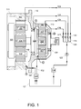
- Figure 1 shows a schematic section view of a gear unit according to an advantageous, exemplifying embodiment of the invention.
- the gear unit disclosed in figure 1 is a planetary gear unit comprising two planet-gear stages.
- the first planet-gear stage comprises a planet-wheel carrier 101, a gear ring 102, planet wheels 103, and a sun gear shaft 104.
- the second planet-gear stage comprises a planet-wheel carrier 105, a gear ring 106, planet wheels 107, and a sun gear shaft 108.
- the planet-wheel carrier 101 of the first planet-gear stage constitutes a part of a mechanical interface structure arranged to receive the mechanical power from a suitable prime mover. Therefore, the planet-wheel carrier 101 of the first planet-gear stage is rotated by the prime mover.
- the gear ring 102 is stationary.
- the sun gear shaft 104 of the first planet-gear stage is connected to the planet-wheel carrier 105 of the second planet-gear stage. Therefore, the planet-wheel carrier 105 of the second planet-gear stage is rotated by the sun gear shaft 104 of the first planet-gear stage.
- the gear ring 106 is stationary.
- the sun gear shaft 108 of the second planet-gear stage may be connected to a rotor of a generator, for example. In the gear unit shown in figure 1 , the sun gear shaft 108 of the second planet-gear stage is floating on support of the planet-wheels 107 of the second planet-gear stage.
- the sun gear shaft 104 of the first planet-gear stage is floating on support of the planet-wheels 104 of the first planet-gear stage and on support of the planet-wheel carrier 105 of the second planet-gear stage. It is, however, also possible that one or both of the sun gear shafts is/are bearing-mounted.
- the stationary gear ring 102 forms part of the frame of the first gear stage
- the stationary gear ring 106 form part of the frame of the second gear stage.
- the frame of the gear unit which in the embodiment of figure 1 comprises frame parts 111, 112 and 113 in addition to the gear rings 102 and 106, may be manufactured as a single entity, in a single casting, for example.
- This kind of single frame piece for the gear unit enhances the structural strength of the frame, and allows for better conveying of the forces from within the gear unit to the frame of the unit and from there to suitable external mechanical fastening structures.
- the gear unit of figure 1 also has a lubrication system for lubricating bearings 109, 110, and the gears of the gear stages.
- the lubrication system comprises a lubrication fluid tank which in this case is a lubrication oil tank 121, a lubrication pump 122, lubrication channeling 123-126 for feeding the lubrication oil into the gear unit, controllable valves 127-130 for controlling the amount of lubrication oil fed to the gear unit, lubrication oil channeling 131, 132 for draining lubrication oil from the gear unit, a lubrication oil cooling element 123, and a lubrication oil filter element 134.
- the lubrication system of the gear unit may also comprise other parts and elements such as lubrication oil pre-heating elements.
- the gear unit also comprises temperature sensors A-D.
- the temperature sensor A measures the temperature of the bearing 109
- the temperature sensor B measures the temperature of the bearing 110
- the temperature sensor C measures the temperature of the lubrication oil used to lubricate the second gear stage
- the temperature sensor D measures the temperature of the lubrication oil used to lubricate the first gear stage.
- the temperature sensors used may be thermo couples, Pt100s, Pt 1000s or temperature transducers, for example.
- the controllable valves 127-130 are controlled on basis of the temperature measurement data from the temperature sensors A-D so, that the volume of lubrication oil passing through the controllable valves 127-130 is increased or decreased. In this way a greater portion of the lubrication oil can be fed to the gear stage and/or bearing with higher temperature(s), and smaller portion of the lubrication oil can be fed to the gear stage and/or bearing with lower temperature.
- the controlling of the controllable valves 127-130 may be advantageously carried out by an automatic controlling system.
- the gear unit of figure 2 is also a planetary gear unit where the controlling of the lubrication system is formed in accordance of another embodiment of the present invention.
- valves 207-209 controls the proportions of lubrication oil directed to the first and second gear stage of the gear unit via lubrication channels 203 and 204.
- the second valve group consisting of valves 210-212, controls the proportions of lubrication oil directed to the bearings 109 and 110 of the gear unit via lubrication channels 206 and 205.
- closing any of the valves 207-212 affects the whole lubrication system.
- closing of valve 207 increases pressure difference in channel 213, 203, which causes increase of lubrication fluid flow in lubrication channels 205 and 206.
- the on/off -type valves 207-209 and 210-212 are closed and opened on basis of the temperature measurement data from the temperature sensors A-D.
- the temperature data from temperature sensors A and B is used to direct greater portion of lubrication oil to the bearing with higher temperature by opening and closing the valves 207-209 of the first valve group.
- the temperature data from temperature sensors C and D is used to direct greater portion of lubrication oil to the gear stage with higher temperature by opening and closing the valves 210-212 of the second valve group.
- the controlling of the on/off valves 207-209 and 210-212 on basis of the measured temperature data may be advantageously carried out by an automatic controlling system.
- the lubrication oil pump 201 comprises an electric motor, and the oil pump is equipped with frequency controller 202, which enables controlling of the rotational speed of the oil pump. This way the oil pressure within the lubrication system can be varied.
- controlling of the proportions of lubrication oil directed to different parts of the gear unit can also be achieved by use of controllable rotation speed oil pump together with choker arrangements within the lubrication channeling.
- gear units comprise, but are not restricted to, different type of planetary gear units and different type of bevel gear units, for example.
Landscapes
- Engineering & Computer Science (AREA)
- General Engineering & Computer Science (AREA)
- Mechanical Engineering (AREA)
- General Details Of Gearings (AREA)
Claims (8)
- Procédé de commande de la lubrification d'une unité d'engrenage, procédé dans lequel la température d'un fluide de lubrification circulant dans un conduit de lubrification (123-126) d'une unité d'engrenage est mesurée, caractérisé en ce que la température du fluide de lubrification est mesurée à au moins deux emplacements de l'unité d'engrenage, et une proportion plus grande du fluide de lubrification est dirigée vers l'emplacement plus chaud des au moins deux emplacements, et la proportion correspondante plus petite du fluide de lubrification est dirigée vers l'emplacement plus froid des au moins deux emplacements.
- Procédé selon la revendication 1, dans lequel la proportion du fluide de lubrification dirigée vers des emplacements différents est commandée au moins partiellement par au moins une vanne (127-130).
- Procédé selon la revendication 1 ou 2, dans lequel la proportion de fluide de lubrification dirigé vers différents emplacements est commandée au moins partiellement par la vitesse de rotation d'une pompe de fluide de lubrification (122).
- Unité d'engrenage comprenant :un premier arbre (104) et un deuxième arbre (103) pour la connexion à un système mécanique externe,au moins un étage d'engrenage (105-107) entre les premier et deuxième arbres ;un conduit (123-126) pour amener le fluide de lubrification à se diriger à travers au moins un étage d'engrenage précité et des paliers (109-110) de l'unité d'engrenage ;
caractérisée en ce qu'elle comprend en outre deux ou plusieurs capteurs de température (A-D) pour mesurer la température du fluide de lubrification d'au moins deux emplacements de l'unité d'engrenage et pour fournir au moins deux signaux de température représentatifs de celle-ci,et en ce que le conduit (123-126) comprend au moins une vanne (127-130) apte à être contrôlée pour changer la distribution de l'écoulement du fluide de lubrification entre des branches du conduit, et l'unité d'engrenage comprend un dispositif de commande pour commander au moins une vanne apte à être contrôlée (127-130) sur la base des au moins deux signaux de température de manière à augmenter la proportion du fluide de lubrification s'écoulant à l'emplacement plus chaud des au moins deux emplacements de l'engrenage et, d'une manière correspondante, pour diminuer la proportion du fluide de lubrification s'écoulant vers l'emplacement plus froid des au moins deux emplacements de l'unité d'engrenage. - Unité d'engrenage selon la revendication 4, dans laquelle au moins une vanne apte à être contrôlée (127-130) est une vanne numérique ayant deux positions possibles: ouverte et fermée.
- Unité d'engrenage selon la revendication 4, dans laquelle au moins une vanne apte à être contrôlée (127-130) comprend deux ou plusieurs vannes numériques connectées en parallèle, chacune ayant deux positions : ouverte et fermée.
- Unité d'engrenage selon l'une quelconque des revendications 4 à 6, dans laquelle chacune des au moins une vanne apte à être contrôlée (127-130) est une vanne à commande électrique.
- Unité d'engrenage selon la revendication 4, dans laquelle l'unité d'engrenage comprend une pompe de fluide de lubrification (122) pour amener le fluide de lubrification à s'écouler dans le conduit, et le dispositif de commande est agencé pour commander la vitesse de rotation de la pompe du fluide de lubrification au moins partiellement sur la base de la position d'au moins une vanne apte à être contrôlée précitée (127-130).
Priority Applications (9)
| Application Number | Priority Date | Filing Date | Title |
|---|---|---|---|
| ES11182334.0T ES2479692T3 (es) | 2011-09-22 | 2011-09-22 | Un procedimiento para controlar la lubricación de una transmisión y una transmisión |
| DK11182334T DK2573429T3 (da) | 2011-09-22 | 2011-09-22 | Fremgangsmåde til styring af smøringen af en drevenhed, og en drevenhed |
| EP20110182334 EP2573429B1 (fr) | 2011-09-22 | 2011-09-22 | Procédé de contrôle d'une pompe de lubrification d'une unité d'engrenage et unité d'engrenage |
| CA2790512A CA2790512C (fr) | 2011-09-22 | 2012-09-20 | Une methode pour controler la lubrification d'un engrenage et engrenage |
| US13/624,504 US20130074629A1 (en) | 2011-09-22 | 2012-09-21 | Method for controlling lubrication of a gear unit and a gear unit |
| CN201210449186.XA CN103062379B (zh) | 2011-09-22 | 2012-09-21 | 用于控制齿轮单元的润滑的方法以及齿轮单元 |
| BR102012024134-0A BR102012024134B1 (pt) | 2011-09-22 | 2012-09-24 | Método para controlar a lubrificação de uma unidade de engrenagem e uma unidade de engrenagem |
| KR1020120106133A KR101848299B1 (ko) | 2011-09-22 | 2012-09-24 | 기어유닛의 윤활을 제어하는 방법 및 기어유닛 |
| HK13106409.7A HK1179325B (en) | 2013-05-30 | A method for controlling lubrication of a gear unit and a gear unit |
Applications Claiming Priority (1)
| Application Number | Priority Date | Filing Date | Title |
|---|---|---|---|
| EP20110182334 EP2573429B1 (fr) | 2011-09-22 | 2011-09-22 | Procédé de contrôle d'une pompe de lubrification d'une unité d'engrenage et unité d'engrenage |
Publications (2)
| Publication Number | Publication Date |
|---|---|
| EP2573429A1 EP2573429A1 (fr) | 2013-03-27 |
| EP2573429B1 true EP2573429B1 (fr) | 2014-04-23 |
Family
ID=44907735
Family Applications (1)
| Application Number | Title | Priority Date | Filing Date |
|---|---|---|---|
| EP20110182334 Not-in-force EP2573429B1 (fr) | 2011-09-22 | 2011-09-22 | Procédé de contrôle d'une pompe de lubrification d'une unité d'engrenage et unité d'engrenage |
Country Status (8)
| Country | Link |
|---|---|
| US (1) | US20130074629A1 (fr) |
| EP (1) | EP2573429B1 (fr) |
| KR (1) | KR101848299B1 (fr) |
| CN (1) | CN103062379B (fr) |
| BR (1) | BR102012024134B1 (fr) |
| CA (1) | CA2790512C (fr) |
| DK (1) | DK2573429T3 (fr) |
| ES (1) | ES2479692T3 (fr) |
Families Citing this family (12)
| Publication number | Priority date | Publication date | Assignee | Title |
|---|---|---|---|---|
| EP2573388B1 (fr) * | 2011-09-22 | 2018-11-07 | Moventas Gears Oy | Procédé de contrôle d'une pompe de lubrification d'une unité d'engrenage et unité d'engrenage |
| CN103821673B (zh) * | 2013-11-25 | 2016-06-22 | 华北电力大学(保定) | 一种基于结构分析的风机齿轮箱振动传感器配置方法 |
| CN104006121A (zh) * | 2014-05-21 | 2014-08-27 | 中山市雅太电器有限公司 | 行星齿轮变速箱及设置有行星齿轮变速箱的船用推进器 |
| EP3332103B1 (fr) | 2015-08-07 | 2022-09-14 | Sikorsky Aircraft Corporation | Systèmes de lubrification destinés à des transmissions |
| CN106837554B (zh) * | 2017-02-16 | 2019-04-23 | 中国航发沈阳发动机研究所 | 一种发动机传动系统多喷点供油油量分配方法 |
| CN108240545B (zh) * | 2018-03-16 | 2023-06-16 | 中铁隧道局集团有限公司 | 一种移动式隧道掘进机多功能液压泵站 |
| CN108980323B (zh) * | 2018-08-24 | 2024-05-14 | 南京高速齿轮制造有限公司 | 大兆瓦级风电主齿轮箱风量控制润滑系统 |
| DE102020122218A1 (de) | 2020-08-25 | 2022-03-03 | Rolls-Royce Deutschland Ltd & Co Kg | Verfahren und Steuergerät zum Ermitteln von Lagertemperaturen von Gleitlagern von Planetenrädern im Betrieb eines Planetengetriebes |
| DE102020122212A1 (de) | 2020-08-25 | 2022-03-03 | Rolls-Royce Deutschland Ltd & Co Kg | Planetengetriebe und Gasturbinentriebwerk |
| CN112377604B (zh) * | 2020-12-01 | 2021-12-14 | 浙江恒齿传动股份有限公司 | 一种智能型减速机 |
| EP4124780A1 (fr) * | 2021-07-30 | 2023-02-01 | General Electric Company | Système d'alimentation en huile avec pompe à vide pour boîte de vitesses de système d'entraînement |
| CN117386792B (zh) * | 2023-10-16 | 2025-07-29 | 东风汽车集团股份有限公司 | 润滑流量的控制方法及设备 |
Family Cites Families (19)
| Publication number | Priority date | Publication date | Assignee | Title |
|---|---|---|---|---|
| DE3904952C1 (fr) * | 1989-02-16 | 1990-07-26 | Willy Vogel Ag, 1000 Berlin, De | |
| DE4122889C1 (fr) * | 1991-07-11 | 1992-12-17 | Bitzer Kuehlmaschinenbau Gmbh & Co Kg, 7032 Sindelfingen, De | |
| US5711615A (en) * | 1993-03-18 | 1998-01-27 | Barmag Ag | Antifriction bearing |
| JPH11337449A (ja) * | 1998-05-27 | 1999-12-10 | Hitachi Ltd | 歯車装置 |
| US6092628A (en) * | 1998-09-28 | 2000-07-25 | Caterpillar, Inc. | Apparatus and method for controlling temperature of fluid in a differential assembly |
| DE19912328A1 (de) | 1999-03-19 | 2000-09-21 | Zahnradfabrik Friedrichshafen | Vorrichtung zur Ölführung in einem Getriebe eines Kraftfahrzeuges |
| GB2382117B (en) * | 2001-10-05 | 2005-07-20 | Hansen Transmissions Int | Wind turbine gear unit lubrication |
| GB2388634A (en) * | 2002-05-15 | 2003-11-19 | Dana Automotive Ltd | Engine lubrication system having dual/auxiliary pump operation |
| DE102005032633A1 (de) * | 2005-07-13 | 2007-01-25 | Robert Bosch Gmbh | Verfahren zur Beeinflussung der Temperatur eines elektromechanischen Bauteils und Vorrichtung zur Durchführung des Verfahrens |
| ATE453783T1 (de) * | 2005-10-14 | 2010-01-15 | Renault Trucks | Schmiersystem und solch ein system umfassender verbrennungsmotor |
| SE530241C2 (sv) * | 2006-10-03 | 2008-04-08 | Scania Cv Ab | Arrangemang för att kyla olja i en växellåda i ett fordon |
| JP2008291897A (ja) * | 2007-05-23 | 2008-12-04 | Nsk Warner Kk | 発進クラッチの潤滑制御方法及び潤滑制御装置 |
| JP5011052B2 (ja) * | 2007-10-03 | 2012-08-29 | 株式会社日立ニコトランスミッション | 歯車装置 |
| DE102009019814A1 (de) * | 2009-05-02 | 2010-11-04 | Bayerische Motoren Werke Aktiengesellschaft | Getriebe für Fahrzeuge |
| US20120241258A1 (en) * | 2011-03-23 | 2012-09-27 | Pradip Radhakrishnan Subramaniam | Lubricant supply system and method for controlling gearbox lubrication |
| EP2573388B1 (fr) * | 2011-09-22 | 2018-11-07 | Moventas Gears Oy | Procédé de contrôle d'une pompe de lubrification d'une unité d'engrenage et unité d'engrenage |
| DK2573428T3 (en) * | 2011-09-22 | 2017-04-03 | Moventas Gears Oy | Gear unit and method for controlling a gear unit lubrication pump |
| DK2573391T3 (en) * | 2011-09-22 | 2019-01-21 | Moventas Gears Oy | Method and arrangement for controlling the lubrication of an exchange |
| US8919299B2 (en) * | 2011-12-19 | 2014-12-30 | Chrysler Group Llc | System and method to control automotive powertrain component temperature |
-
2011
- 2011-09-22 EP EP20110182334 patent/EP2573429B1/fr not_active Not-in-force
- 2011-09-22 ES ES11182334.0T patent/ES2479692T3/es active Active
- 2011-09-22 DK DK11182334T patent/DK2573429T3/da active
-
2012
- 2012-09-20 CA CA2790512A patent/CA2790512C/fr active Active
- 2012-09-21 US US13/624,504 patent/US20130074629A1/en not_active Abandoned
- 2012-09-21 CN CN201210449186.XA patent/CN103062379B/zh not_active Expired - Fee Related
- 2012-09-24 BR BR102012024134-0A patent/BR102012024134B1/pt not_active IP Right Cessation
- 2012-09-24 KR KR1020120106133A patent/KR101848299B1/ko not_active Expired - Fee Related
Also Published As
| Publication number | Publication date |
|---|---|
| CA2790512A1 (fr) | 2013-03-22 |
| CN103062379B (zh) | 2016-08-10 |
| HK1179325A1 (en) | 2013-09-27 |
| BR102012024134B1 (pt) | 2021-12-21 |
| BR102012024134A8 (pt) | 2016-03-15 |
| ES2479692T3 (es) | 2014-07-24 |
| EP2573429A1 (fr) | 2013-03-27 |
| CN103062379A (zh) | 2013-04-24 |
| BR102012024134A2 (pt) | 2014-08-26 |
| US20130074629A1 (en) | 2013-03-28 |
| KR20130032291A (ko) | 2013-04-01 |
| KR101848299B1 (ko) | 2018-04-12 |
| DK2573429T3 (da) | 2014-07-21 |
| CA2790512C (fr) | 2019-10-15 |
Similar Documents
| Publication | Publication Date | Title |
|---|---|---|
| CA2790512C (fr) | Une methode pour controler la lubrification d'un engrenage et engrenage | |
| EP2573388B1 (fr) | Procédé de contrôle d'une pompe de lubrification d'une unité d'engrenage et unité d'engrenage | |
| US8869940B2 (en) | Dual temperature oil control system and method for a wind turbine gearbox | |
| EP2573391B1 (fr) | Procédé et agencement pour contrôler la lubrification d'un système d'engrenage | |
| EP3227584B1 (fr) | Système de lubrification et procédé pour commander le système de lubrification | |
| CN103836168A (zh) | 行星齿轮装置 | |
| US10309518B2 (en) | Gear unit and a method for heating lubricant oil of a gear unit | |
| JP2020078977A (ja) | 動力伝達装置の冷却装置 | |
| CN104913035A (zh) | 变速器润滑系统 | |
| US20130049371A1 (en) | Oil supply in renewable energy turbine generator | |
| US20130011263A1 (en) | System and method for lubricant flow control | |
| US8629591B2 (en) | Electromechanical device | |
| US9879532B2 (en) | Adaptation of a hydraulic motor | |
| HK1179325B (en) | A method for controlling lubrication of a gear unit and a gear unit | |
| US20130343888A1 (en) | Wind turbine and a method of operating a wind turbine | |
| TWI330701B (en) | Planetengetriebe | |
| CN108980323A (zh) | 大兆瓦级风电主齿轮箱风量控制润滑系统 | |
| HK1179321B (en) | A method for controlling lubrication of a gear unit and a gear unit | |
| HK1179321A (en) | A method for controlling lubrication of a gear unit and a gear unit | |
| JP7815824B2 (ja) | 回転体装置 | |
| JP2011526345A (ja) | 円錐形の摩擦リング伝達装置 |
Legal Events
| Date | Code | Title | Description |
|---|---|---|---|
| PUAI | Public reference made under article 153(3) epc to a published international application that has entered the european phase |
Free format text: ORIGINAL CODE: 0009012 |
|
| AK | Designated contracting states |
Kind code of ref document: A1 Designated state(s): AL AT BE BG CH CY CZ DE DK EE ES FI FR GB GR HR HU IE IS IT LI LT LU LV MC MK MT NL NO PL PT RO RS SE SI SK SM TR |
|
| AX | Request for extension of the european patent |
Extension state: BA ME |
|
| REG | Reference to a national code |
Ref country code: HK Ref legal event code: DE Ref document number: 1179325 Country of ref document: HK |
|
| 17P | Request for examination filed |
Effective date: 20130828 |
|
| RBV | Designated contracting states (corrected) |
Designated state(s): AL AT BE BG CH CY CZ DE DK EE ES FI FR GB GR HR HU IE IS IT LI LT LU LV MC MK MT NL NO PL PT RO RS SE SI SK SM TR |
|
| GRAP | Despatch of communication of intention to grant a patent |
Free format text: ORIGINAL CODE: EPIDOSNIGR1 |
|
| INTG | Intention to grant announced |
Effective date: 20131115 |
|
| GRAS | Grant fee paid |
Free format text: ORIGINAL CODE: EPIDOSNIGR3 |
|
| GRAA | (expected) grant |
Free format text: ORIGINAL CODE: 0009210 |
|
| AK | Designated contracting states |
Kind code of ref document: B1 Designated state(s): AL AT BE BG CH CY CZ DE DK EE ES FI FR GB GR HR HU IE IS IT LI LT LU LV MC MK MT NL NO PL PT RO RS SE SI SK SM TR |
|
| REG | Reference to a national code |
Ref country code: GB Ref legal event code: FG4D |
|
| REG | Reference to a national code |
Ref country code: CH Ref legal event code: EP |
|
| REG | Reference to a national code |
Ref country code: AT Ref legal event code: REF Ref document number: 664057 Country of ref document: AT Kind code of ref document: T Effective date: 20140515 |
|
| REG | Reference to a national code |
Ref country code: IE Ref legal event code: FG4D |
|
| REG | Reference to a national code |
Ref country code: DE Ref legal event code: R096 Ref document number: 602011006344 Country of ref document: DE Effective date: 20140605 |
|
| REG | Reference to a national code |
Ref country code: DK Ref legal event code: T3 Effective date: 20140716 |
|
| REG | Reference to a national code |
Ref country code: ES Ref legal event code: FG2A Ref document number: 2479692 Country of ref document: ES Kind code of ref document: T3 Effective date: 20140724 |
|
| REG | Reference to a national code |
Ref country code: HK Ref legal event code: GR Ref document number: 1179325 Country of ref document: HK |
|
| REG | Reference to a national code |
Ref country code: AT Ref legal event code: MK05 Ref document number: 664057 Country of ref document: AT Kind code of ref document: T Effective date: 20140423 |
|
| REG | Reference to a national code |
Ref country code: NL Ref legal event code: VDEP Effective date: 20140423 |
|
| REG | Reference to a national code |
Ref country code: LT Ref legal event code: MG4D |
|
| PG25 | Lapsed in a contracting state [announced via postgrant information from national office to epo] |
Ref country code: GR Free format text: LAPSE BECAUSE OF FAILURE TO SUBMIT A TRANSLATION OF THE DESCRIPTION OR TO PAY THE FEE WITHIN THE PRESCRIBED TIME-LIMIT Effective date: 20140724 Ref country code: IS Free format text: LAPSE BECAUSE OF FAILURE TO SUBMIT A TRANSLATION OF THE DESCRIPTION OR TO PAY THE FEE WITHIN THE PRESCRIBED TIME-LIMIT Effective date: 20140823 Ref country code: CY Free format text: LAPSE BECAUSE OF FAILURE TO SUBMIT A TRANSLATION OF THE DESCRIPTION OR TO PAY THE FEE WITHIN THE PRESCRIBED TIME-LIMIT Effective date: 20140423 Ref country code: LT Free format text: LAPSE BECAUSE OF FAILURE TO SUBMIT A TRANSLATION OF THE DESCRIPTION OR TO PAY THE FEE WITHIN THE PRESCRIBED TIME-LIMIT Effective date: 20140423 Ref country code: NO Free format text: LAPSE BECAUSE OF FAILURE TO SUBMIT A TRANSLATION OF THE DESCRIPTION OR TO PAY THE FEE WITHIN THE PRESCRIBED TIME-LIMIT Effective date: 20140723 Ref country code: BG Free format text: LAPSE BECAUSE OF FAILURE TO SUBMIT A TRANSLATION OF THE DESCRIPTION OR TO PAY THE FEE WITHIN THE PRESCRIBED TIME-LIMIT Effective date: 20140723 Ref country code: NL Free format text: LAPSE BECAUSE OF FAILURE TO SUBMIT A TRANSLATION OF THE DESCRIPTION OR TO PAY THE FEE WITHIN THE PRESCRIBED TIME-LIMIT Effective date: 20140423 |
|
| PG25 | Lapsed in a contracting state [announced via postgrant information from national office to epo] |
Ref country code: HR Free format text: LAPSE BECAUSE OF FAILURE TO SUBMIT A TRANSLATION OF THE DESCRIPTION OR TO PAY THE FEE WITHIN THE PRESCRIBED TIME-LIMIT Effective date: 20140423 Ref country code: PL Free format text: LAPSE BECAUSE OF FAILURE TO SUBMIT A TRANSLATION OF THE DESCRIPTION OR TO PAY THE FEE WITHIN THE PRESCRIBED TIME-LIMIT Effective date: 20140423 Ref country code: RS Free format text: LAPSE BECAUSE OF FAILURE TO SUBMIT A TRANSLATION OF THE DESCRIPTION OR TO PAY THE FEE WITHIN THE PRESCRIBED TIME-LIMIT Effective date: 20140423 Ref country code: AT Free format text: LAPSE BECAUSE OF FAILURE TO SUBMIT A TRANSLATION OF THE DESCRIPTION OR TO PAY THE FEE WITHIN THE PRESCRIBED TIME-LIMIT Effective date: 20140423 Ref country code: SE Free format text: LAPSE BECAUSE OF FAILURE TO SUBMIT A TRANSLATION OF THE DESCRIPTION OR TO PAY THE FEE WITHIN THE PRESCRIBED TIME-LIMIT Effective date: 20140423 Ref country code: LV Free format text: LAPSE BECAUSE OF FAILURE TO SUBMIT A TRANSLATION OF THE DESCRIPTION OR TO PAY THE FEE WITHIN THE PRESCRIBED TIME-LIMIT Effective date: 20140423 |
|
| PG25 | Lapsed in a contracting state [announced via postgrant information from national office to epo] |
Ref country code: PT Free format text: LAPSE BECAUSE OF FAILURE TO SUBMIT A TRANSLATION OF THE DESCRIPTION OR TO PAY THE FEE WITHIN THE PRESCRIBED TIME-LIMIT Effective date: 20140825 |
|
| REG | Reference to a national code |
Ref country code: DE Ref legal event code: R097 Ref document number: 602011006344 Country of ref document: DE |
|
| PG25 | Lapsed in a contracting state [announced via postgrant information from national office to epo] |
Ref country code: SK Free format text: LAPSE BECAUSE OF FAILURE TO SUBMIT A TRANSLATION OF THE DESCRIPTION OR TO PAY THE FEE WITHIN THE PRESCRIBED TIME-LIMIT Effective date: 20140423 Ref country code: EE Free format text: LAPSE BECAUSE OF FAILURE TO SUBMIT A TRANSLATION OF THE DESCRIPTION OR TO PAY THE FEE WITHIN THE PRESCRIBED TIME-LIMIT Effective date: 20140423 Ref country code: RO Free format text: LAPSE BECAUSE OF FAILURE TO SUBMIT A TRANSLATION OF THE DESCRIPTION OR TO PAY THE FEE WITHIN THE PRESCRIBED TIME-LIMIT Effective date: 20140423 |
|
| PLBE | No opposition filed within time limit |
Free format text: ORIGINAL CODE: 0009261 |
|
| STAA | Information on the status of an ep patent application or granted ep patent |
Free format text: STATUS: NO OPPOSITION FILED WITHIN TIME LIMIT |
|
| 26N | No opposition filed |
Effective date: 20150126 |
|
| PG25 | Lapsed in a contracting state [announced via postgrant information from national office to epo] |
Ref country code: MC Free format text: LAPSE BECAUSE OF FAILURE TO SUBMIT A TRANSLATION OF THE DESCRIPTION OR TO PAY THE FEE WITHIN THE PRESCRIBED TIME-LIMIT Effective date: 20140423 Ref country code: LU Free format text: LAPSE BECAUSE OF FAILURE TO SUBMIT A TRANSLATION OF THE DESCRIPTION OR TO PAY THE FEE WITHIN THE PRESCRIBED TIME-LIMIT Effective date: 20140922 |
|
| REG | Reference to a national code |
Ref country code: CH Ref legal event code: PL |
|
| REG | Reference to a national code |
Ref country code: DE Ref legal event code: R097 Ref document number: 602011006344 Country of ref document: DE Effective date: 20150126 |
|
| REG | Reference to a national code |
Ref country code: IE Ref legal event code: MM4A |
|
| PG25 | Lapsed in a contracting state [announced via postgrant information from national office to epo] |
Ref country code: CH Free format text: LAPSE BECAUSE OF NON-PAYMENT OF DUE FEES Effective date: 20140930 Ref country code: SI Free format text: LAPSE BECAUSE OF FAILURE TO SUBMIT A TRANSLATION OF THE DESCRIPTION OR TO PAY THE FEE WITHIN THE PRESCRIBED TIME-LIMIT Effective date: 20140423 Ref country code: LI Free format text: LAPSE BECAUSE OF NON-PAYMENT OF DUE FEES Effective date: 20140930 |
|
| PG25 | Lapsed in a contracting state [announced via postgrant information from national office to epo] |
Ref country code: IE Free format text: LAPSE BECAUSE OF NON-PAYMENT OF DUE FEES Effective date: 20140922 |
|
| PG25 | Lapsed in a contracting state [announced via postgrant information from national office to epo] |
Ref country code: SM Free format text: LAPSE BECAUSE OF FAILURE TO SUBMIT A TRANSLATION OF THE DESCRIPTION OR TO PAY THE FEE WITHIN THE PRESCRIBED TIME-LIMIT Effective date: 20140423 |
|
| PG25 | Lapsed in a contracting state [announced via postgrant information from national office to epo] |
Ref country code: MT Free format text: LAPSE BECAUSE OF FAILURE TO SUBMIT A TRANSLATION OF THE DESCRIPTION OR TO PAY THE FEE WITHIN THE PRESCRIBED TIME-LIMIT Effective date: 20140423 |
|
| PG25 | Lapsed in a contracting state [announced via postgrant information from national office to epo] |
Ref country code: TR Free format text: LAPSE BECAUSE OF FAILURE TO SUBMIT A TRANSLATION OF THE DESCRIPTION OR TO PAY THE FEE WITHIN THE PRESCRIBED TIME-LIMIT Effective date: 20140423 Ref country code: HU Free format text: LAPSE BECAUSE OF FAILURE TO SUBMIT A TRANSLATION OF THE DESCRIPTION OR TO PAY THE FEE WITHIN THE PRESCRIBED TIME-LIMIT; INVALID AB INITIO Effective date: 20110922 |
|
| REG | Reference to a national code |
Ref country code: FR Ref legal event code: PLFP Year of fee payment: 6 |
|
| REG | Reference to a national code |
Ref country code: FR Ref legal event code: PLFP Year of fee payment: 7 |
|
| PG25 | Lapsed in a contracting state [announced via postgrant information from national office to epo] |
Ref country code: MK Free format text: LAPSE BECAUSE OF FAILURE TO SUBMIT A TRANSLATION OF THE DESCRIPTION OR TO PAY THE FEE WITHIN THE PRESCRIBED TIME-LIMIT Effective date: 20140423 |
|
| REG | Reference to a national code |
Ref country code: FR Ref legal event code: PLFP Year of fee payment: 8 |
|
| PG25 | Lapsed in a contracting state [announced via postgrant information from national office to epo] |
Ref country code: AL Free format text: LAPSE BECAUSE OF FAILURE TO SUBMIT A TRANSLATION OF THE DESCRIPTION OR TO PAY THE FEE WITHIN THE PRESCRIBED TIME-LIMIT Effective date: 20140423 |
|
| PGFP | Annual fee paid to national office [announced via postgrant information from national office to epo] |
Ref country code: GB Payment date: 20220920 Year of fee payment: 12 Ref country code: FI Payment date: 20220921 Year of fee payment: 12 Ref country code: DK Payment date: 20220922 Year of fee payment: 12 Ref country code: DE Payment date: 20220920 Year of fee payment: 12 Ref country code: CZ Payment date: 20220915 Year of fee payment: 12 |
|
| PGFP | Annual fee paid to national office [announced via postgrant information from national office to epo] |
Ref country code: FR Payment date: 20220922 Year of fee payment: 12 Ref country code: BE Payment date: 20220920 Year of fee payment: 12 |
|
| PGFP | Annual fee paid to national office [announced via postgrant information from national office to epo] |
Ref country code: IT Payment date: 20220926 Year of fee payment: 12 Ref country code: ES Payment date: 20221122 Year of fee payment: 12 |
|
| REG | Reference to a national code |
Ref country code: DE Ref legal event code: R119 Ref document number: 602011006344 Country of ref document: DE |
|
| REG | Reference to a national code |
Ref country code: DK Ref legal event code: EBP Effective date: 20230930 |
|
| PG25 | Lapsed in a contracting state [announced via postgrant information from national office to epo] |
Ref country code: FI Free format text: LAPSE BECAUSE OF NON-PAYMENT OF DUE FEES Effective date: 20230922 Ref country code: CZ Free format text: LAPSE BECAUSE OF NON-PAYMENT OF DUE FEES Effective date: 20230922 |
|
| REG | Reference to a national code |
Ref country code: BE Ref legal event code: MM Effective date: 20230930 |
|
| GBPC | Gb: european patent ceased through non-payment of renewal fee |
Effective date: 20230922 |
|
| PG25 | Lapsed in a contracting state [announced via postgrant information from national office to epo] |
Ref country code: GB Free format text: LAPSE BECAUSE OF NON-PAYMENT OF DUE FEES Effective date: 20230922 |
|
| PG25 | Lapsed in a contracting state [announced via postgrant information from national office to epo] |
Ref country code: GB Free format text: LAPSE BECAUSE OF NON-PAYMENT OF DUE FEES Effective date: 20230922 Ref country code: FR Free format text: LAPSE BECAUSE OF NON-PAYMENT OF DUE FEES Effective date: 20230930 Ref country code: DE Free format text: LAPSE BECAUSE OF NON-PAYMENT OF DUE FEES Effective date: 20240403 |
|
| PG25 | Lapsed in a contracting state [announced via postgrant information from national office to epo] |
Ref country code: BE Free format text: LAPSE BECAUSE OF NON-PAYMENT OF DUE FEES Effective date: 20230930 |
|
| PG25 | Lapsed in a contracting state [announced via postgrant information from national office to epo] |
Ref country code: DK Free format text: LAPSE BECAUSE OF NON-PAYMENT OF DUE FEES Effective date: 20230930 |
|
| PG25 | Lapsed in a contracting state [announced via postgrant information from national office to epo] |
Ref country code: DK Free format text: LAPSE BECAUSE OF NON-PAYMENT OF DUE FEES Effective date: 20230930 |
|
| REG | Reference to a national code |
Ref country code: ES Ref legal event code: FD2A Effective date: 20241104 |
|
| PG25 | Lapsed in a contracting state [announced via postgrant information from national office to epo] |
Ref country code: IT Free format text: LAPSE BECAUSE OF NON-PAYMENT OF DUE FEES Effective date: 20230922 |
|
| PG25 | Lapsed in a contracting state [announced via postgrant information from national office to epo] |
Ref country code: IT Free format text: LAPSE BECAUSE OF NON-PAYMENT OF DUE FEES Effective date: 20230922 |
|
| PG25 | Lapsed in a contracting state [announced via postgrant information from national office to epo] |
Ref country code: ES Free format text: LAPSE BECAUSE OF NON-PAYMENT OF DUE FEES Effective date: 20230923 |
|
| PG25 | Lapsed in a contracting state [announced via postgrant information from national office to epo] |
Ref country code: ES Free format text: LAPSE BECAUSE OF NON-PAYMENT OF DUE FEES Effective date: 20230923 |