EP2573441A1 - T-Fitting - Google Patents
T-Fitting Download PDFInfo
- Publication number
- EP2573441A1 EP2573441A1 EP11182295A EP11182295A EP2573441A1 EP 2573441 A1 EP2573441 A1 EP 2573441A1 EP 11182295 A EP11182295 A EP 11182295A EP 11182295 A EP11182295 A EP 11182295A EP 2573441 A1 EP2573441 A1 EP 2573441A1
- Authority
- EP
- European Patent Office
- Prior art keywords
- welded
- pipes
- tubes
- penetration curve
- contour
- Prior art date
- Legal status (The legal status is an assumption and is not a legal conclusion. Google has not performed a legal analysis and makes no representation as to the accuracy of the status listed.)
- Withdrawn
Links
- 238000000034 method Methods 0.000 claims abstract description 26
- 230000035515 penetration Effects 0.000 claims description 52
- 238000010438 heat treatment Methods 0.000 claims description 43
- 230000002787 reinforcement Effects 0.000 claims description 14
- 238000004519 manufacturing process Methods 0.000 claims description 11
- 238000003466 welding Methods 0.000 claims description 8
- 239000004033 plastic Substances 0.000 claims description 5
- 239000012815 thermoplastic material Substances 0.000 claims description 4
- 230000003014 reinforcing effect Effects 0.000 claims description 3
- 239000002033 PVDF binder Substances 0.000 claims description 2
- 229920002981 polyvinylidene fluoride Polymers 0.000 claims description 2
- 238000005304 joining Methods 0.000 abstract description 3
- 238000003801 milling Methods 0.000 description 4
- 238000001746 injection moulding Methods 0.000 description 3
- 239000000463 material Substances 0.000 description 2
- 244000089486 Phragmites australis subsp australis Species 0.000 description 1
- 238000005266 casting Methods 0.000 description 1
- 238000010276 construction Methods 0.000 description 1
- 238000005260 corrosion Methods 0.000 description 1
- 230000007797 corrosion Effects 0.000 description 1
- 239000012530 fluid Substances 0.000 description 1
- 239000007789 gas Substances 0.000 description 1
- 239000010865 sewage Substances 0.000 description 1
- 238000010008 shearing Methods 0.000 description 1
- 239000000126 substance Substances 0.000 description 1
- XLYOFNOQVPJJNP-UHFFFAOYSA-N water Substances O XLYOFNOQVPJJNP-UHFFFAOYSA-N 0.000 description 1
Images



Classifications
-
- F—MECHANICAL ENGINEERING; LIGHTING; HEATING; WEAPONS; BLASTING
- F16—ENGINEERING ELEMENTS AND UNITS; GENERAL MEASURES FOR PRODUCING AND MAINTAINING EFFECTIVE FUNCTIONING OF MACHINES OR INSTALLATIONS; THERMAL INSULATION IN GENERAL
- F16L—PIPES; JOINTS OR FITTINGS FOR PIPES; SUPPORTS FOR PIPES, CABLES OR PROTECTIVE TUBING; MEANS FOR THERMAL INSULATION IN GENERAL
- F16L47/00—Connecting arrangements or other fittings specially adapted to be made of plastics or to be used with pipes made of plastics
- F16L47/26—Connecting arrangements or other fittings specially adapted to be made of plastics or to be used with pipes made of plastics for branching pipes; for joining pipes to walls; Adaptors therefor
- F16L47/32—Branch units, e.g. made in one piece, welded, riveted
-
- B—PERFORMING OPERATIONS; TRANSPORTING
- B29—WORKING OF PLASTICS; WORKING OF SUBSTANCES IN A PLASTIC STATE IN GENERAL
- B29C—SHAPING OR JOINING OF PLASTICS; SHAPING OF MATERIAL IN A PLASTIC STATE, NOT OTHERWISE PROVIDED FOR; AFTER-TREATMENT OF THE SHAPED PRODUCTS, e.g. REPAIRING
- B29C65/00—Joining or sealing of preformed parts, e.g. welding of plastics materials; Apparatus therefor
- B29C65/02—Joining or sealing of preformed parts, e.g. welding of plastics materials; Apparatus therefor by heating, with or without pressure
- B29C65/18—Joining or sealing of preformed parts, e.g. welding of plastics materials; Apparatus therefor by heating, with or without pressure using heated tools
- B29C65/20—Joining or sealing of preformed parts, e.g. welding of plastics materials; Apparatus therefor by heating, with or without pressure using heated tools with direct contact, e.g. using "mirror"
-
- B—PERFORMING OPERATIONS; TRANSPORTING
- B29—WORKING OF PLASTICS; WORKING OF SUBSTANCES IN A PLASTIC STATE IN GENERAL
- B29C—SHAPING OR JOINING OF PLASTICS; SHAPING OF MATERIAL IN A PLASTIC STATE, NOT OTHERWISE PROVIDED FOR; AFTER-TREATMENT OF THE SHAPED PRODUCTS, e.g. REPAIRING
- B29C66/00—General aspects of processes or apparatus for joining preformed parts
- B29C66/01—General aspects dealing with the joint area or with the area to be joined
- B29C66/05—Particular design of joint configurations
- B29C66/10—Particular design of joint configurations particular design of the joint cross-sections
- B29C66/11—Joint cross-sections comprising a single joint-segment, i.e. one of the parts to be joined comprising a single joint-segment in the joint cross-section
- B29C66/114—Single butt joints
-
- B—PERFORMING OPERATIONS; TRANSPORTING
- B29—WORKING OF PLASTICS; WORKING OF SUBSTANCES IN A PLASTIC STATE IN GENERAL
- B29C—SHAPING OR JOINING OF PLASTICS; SHAPING OF MATERIAL IN A PLASTIC STATE, NOT OTHERWISE PROVIDED FOR; AFTER-TREATMENT OF THE SHAPED PRODUCTS, e.g. REPAIRING
- B29C66/00—General aspects of processes or apparatus for joining preformed parts
- B29C66/01—General aspects dealing with the joint area or with the area to be joined
- B29C66/05—Particular design of joint configurations
- B29C66/10—Particular design of joint configurations particular design of the joint cross-sections
- B29C66/11—Joint cross-sections comprising a single joint-segment, i.e. one of the parts to be joined comprising a single joint-segment in the joint cross-section
- B29C66/116—Single bevelled joints, i.e. one of the parts to be joined being bevelled in the joint area
-
- B—PERFORMING OPERATIONS; TRANSPORTING
- B29—WORKING OF PLASTICS; WORKING OF SUBSTANCES IN A PLASTIC STATE IN GENERAL
- B29C—SHAPING OR JOINING OF PLASTICS; SHAPING OF MATERIAL IN A PLASTIC STATE, NOT OTHERWISE PROVIDED FOR; AFTER-TREATMENT OF THE SHAPED PRODUCTS, e.g. REPAIRING
- B29C66/00—General aspects of processes or apparatus for joining preformed parts
- B29C66/01—General aspects dealing with the joint area or with the area to be joined
- B29C66/05—Particular design of joint configurations
- B29C66/10—Particular design of joint configurations particular design of the joint cross-sections
- B29C66/11—Joint cross-sections comprising a single joint-segment, i.e. one of the parts to be joined comprising a single joint-segment in the joint cross-section
- B29C66/116—Single bevelled joints, i.e. one of the parts to be joined being bevelled in the joint area
- B29C66/1162—Single bevel to bevel joints, e.g. mitre joints
-
- B—PERFORMING OPERATIONS; TRANSPORTING
- B29—WORKING OF PLASTICS; WORKING OF SUBSTANCES IN A PLASTIC STATE IN GENERAL
- B29C—SHAPING OR JOINING OF PLASTICS; SHAPING OF MATERIAL IN A PLASTIC STATE, NOT OTHERWISE PROVIDED FOR; AFTER-TREATMENT OF THE SHAPED PRODUCTS, e.g. REPAIRING
- B29C66/00—General aspects of processes or apparatus for joining preformed parts
- B29C66/50—General aspects of joining tubular articles; General aspects of joining long products, i.e. bars or profiled elements; General aspects of joining single elements to tubular articles, hollow articles or bars; General aspects of joining several hollow-preforms to form hollow or tubular articles
- B29C66/51—Joining tubular articles, profiled elements or bars; Joining single elements to tubular articles, hollow articles or bars; Joining several hollow-preforms to form hollow or tubular articles
- B29C66/52—Joining tubular articles, bars or profiled elements
- B29C66/522—Joining tubular articles
- B29C66/5224—Joining tubular articles for forming fork-shaped connections, e.g. for making Y-shaped pieces
-
- B—PERFORMING OPERATIONS; TRANSPORTING
- B29—WORKING OF PLASTICS; WORKING OF SUBSTANCES IN A PLASTIC STATE IN GENERAL
- B29C—SHAPING OR JOINING OF PLASTICS; SHAPING OF MATERIAL IN A PLASTIC STATE, NOT OTHERWISE PROVIDED FOR; AFTER-TREATMENT OF THE SHAPED PRODUCTS, e.g. REPAIRING
- B29C66/00—General aspects of processes or apparatus for joining preformed parts
- B29C66/50—General aspects of joining tubular articles; General aspects of joining long products, i.e. bars or profiled elements; General aspects of joining single elements to tubular articles, hollow articles or bars; General aspects of joining several hollow-preforms to form hollow or tubular articles
- B29C66/51—Joining tubular articles, profiled elements or bars; Joining single elements to tubular articles, hollow articles or bars; Joining several hollow-preforms to form hollow or tubular articles
- B29C66/52—Joining tubular articles, bars or profiled elements
- B29C66/522—Joining tubular articles
- B29C66/5224—Joining tubular articles for forming fork-shaped connections, e.g. for making Y-shaped pieces
- B29C66/52241—Joining tubular articles for forming fork-shaped connections, e.g. for making Y-shaped pieces with two right angles, e.g. for making T-shaped pieces
-
- B—PERFORMING OPERATIONS; TRANSPORTING
- B29—WORKING OF PLASTICS; WORKING OF SUBSTANCES IN A PLASTIC STATE IN GENERAL
- B29C—SHAPING OR JOINING OF PLASTICS; SHAPING OF MATERIAL IN A PLASTIC STATE, NOT OTHERWISE PROVIDED FOR; AFTER-TREATMENT OF THE SHAPED PRODUCTS, e.g. REPAIRING
- B29C66/00—General aspects of processes or apparatus for joining preformed parts
- B29C66/70—General aspects of processes or apparatus for joining preformed parts characterised by the composition, physical properties or the structure of the material of the parts to be joined; Joining with non-plastics material
- B29C66/73—General aspects of processes or apparatus for joining preformed parts characterised by the composition, physical properties or the structure of the material of the parts to be joined; Joining with non-plastics material characterised by the intensive physical properties of the material of the parts to be joined, by the optical properties of the material of the parts to be joined, by the extensive physical properties of the parts to be joined, by the state of the material of the parts to be joined or by the material of the parts to be joined being a thermoplastic or a thermoset
- B29C66/739—General aspects of processes or apparatus for joining preformed parts characterised by the composition, physical properties or the structure of the material of the parts to be joined; Joining with non-plastics material characterised by the intensive physical properties of the material of the parts to be joined, by the optical properties of the material of the parts to be joined, by the extensive physical properties of the parts to be joined, by the state of the material of the parts to be joined or by the material of the parts to be joined being a thermoplastic or a thermoset characterised by the material of the parts to be joined being a thermoplastic or a thermoset
- B29C66/7392—General aspects of processes or apparatus for joining preformed parts characterised by the composition, physical properties or the structure of the material of the parts to be joined; Joining with non-plastics material characterised by the intensive physical properties of the material of the parts to be joined, by the optical properties of the material of the parts to be joined, by the extensive physical properties of the parts to be joined, by the state of the material of the parts to be joined or by the material of the parts to be joined being a thermoplastic or a thermoset characterised by the material of the parts to be joined being a thermoplastic or a thermoset characterised by the material of at least one of the parts being a thermoplastic
-
- B—PERFORMING OPERATIONS; TRANSPORTING
- B29—WORKING OF PLASTICS; WORKING OF SUBSTANCES IN A PLASTIC STATE IN GENERAL
- B29C—SHAPING OR JOINING OF PLASTICS; SHAPING OF MATERIAL IN A PLASTIC STATE, NOT OTHERWISE PROVIDED FOR; AFTER-TREATMENT OF THE SHAPED PRODUCTS, e.g. REPAIRING
- B29C66/00—General aspects of processes or apparatus for joining preformed parts
- B29C66/70—General aspects of processes or apparatus for joining preformed parts characterised by the composition, physical properties or the structure of the material of the parts to be joined; Joining with non-plastics material
- B29C66/73—General aspects of processes or apparatus for joining preformed parts characterised by the composition, physical properties or the structure of the material of the parts to be joined; Joining with non-plastics material characterised by the intensive physical properties of the material of the parts to be joined, by the optical properties of the material of the parts to be joined, by the extensive physical properties of the parts to be joined, by the state of the material of the parts to be joined or by the material of the parts to be joined being a thermoplastic or a thermoset
- B29C66/739—General aspects of processes or apparatus for joining preformed parts characterised by the composition, physical properties or the structure of the material of the parts to be joined; Joining with non-plastics material characterised by the intensive physical properties of the material of the parts to be joined, by the optical properties of the material of the parts to be joined, by the extensive physical properties of the parts to be joined, by the state of the material of the parts to be joined or by the material of the parts to be joined being a thermoplastic or a thermoset characterised by the material of the parts to be joined being a thermoplastic or a thermoset
- B29C66/7392—General aspects of processes or apparatus for joining preformed parts characterised by the composition, physical properties or the structure of the material of the parts to be joined; Joining with non-plastics material characterised by the intensive physical properties of the material of the parts to be joined, by the optical properties of the material of the parts to be joined, by the extensive physical properties of the parts to be joined, by the state of the material of the parts to be joined or by the material of the parts to be joined being a thermoplastic or a thermoset characterised by the material of the parts to be joined being a thermoplastic or a thermoset characterised by the material of at least one of the parts being a thermoplastic
- B29C66/73921—General aspects of processes or apparatus for joining preformed parts characterised by the composition, physical properties or the structure of the material of the parts to be joined; Joining with non-plastics material characterised by the intensive physical properties of the material of the parts to be joined, by the optical properties of the material of the parts to be joined, by the extensive physical properties of the parts to be joined, by the state of the material of the parts to be joined or by the material of the parts to be joined being a thermoplastic or a thermoset characterised by the material of the parts to be joined being a thermoplastic or a thermoset characterised by the material of at least one of the parts being a thermoplastic characterised by the materials of both parts being thermoplastics
-
- B—PERFORMING OPERATIONS; TRANSPORTING
- B29—WORKING OF PLASTICS; WORKING OF SUBSTANCES IN A PLASTIC STATE IN GENERAL
- B29C—SHAPING OR JOINING OF PLASTICS; SHAPING OF MATERIAL IN A PLASTIC STATE, NOT OTHERWISE PROVIDED FOR; AFTER-TREATMENT OF THE SHAPED PRODUCTS, e.g. REPAIRING
- B29C66/00—General aspects of processes or apparatus for joining preformed parts
- B29C66/80—General aspects of machine operations or constructions and parts thereof
- B29C66/81—General aspects of the pressing elements, i.e. the elements applying pressure on the parts to be joined in the area to be joined, e.g. the welding jaws or clamps
- B29C66/814—General aspects of the pressing elements, i.e. the elements applying pressure on the parts to be joined in the area to be joined, e.g. the welding jaws or clamps characterised by the design of the pressing elements, e.g. of the welding jaws or clamps
- B29C66/8141—General aspects of the pressing elements, i.e. the elements applying pressure on the parts to be joined in the area to be joined, e.g. the welding jaws or clamps characterised by the design of the pressing elements, e.g. of the welding jaws or clamps characterised by the surface geometry of the part of the pressing elements, e.g. welding jaws or clamps, coming into contact with the parts to be joined
- B29C66/81411—General aspects of the pressing elements, i.e. the elements applying pressure on the parts to be joined in the area to be joined, e.g. the welding jaws or clamps characterised by the design of the pressing elements, e.g. of the welding jaws or clamps characterised by the surface geometry of the part of the pressing elements, e.g. welding jaws or clamps, coming into contact with the parts to be joined characterised by its cross-section, e.g. transversal or longitudinal, being non-flat
-
- B—PERFORMING OPERATIONS; TRANSPORTING
- B29—WORKING OF PLASTICS; WORKING OF SUBSTANCES IN A PLASTIC STATE IN GENERAL
- B29C—SHAPING OR JOINING OF PLASTICS; SHAPING OF MATERIAL IN A PLASTIC STATE, NOT OTHERWISE PROVIDED FOR; AFTER-TREATMENT OF THE SHAPED PRODUCTS, e.g. REPAIRING
- B29C66/00—General aspects of processes or apparatus for joining preformed parts
- B29C66/80—General aspects of machine operations or constructions and parts thereof
- B29C66/81—General aspects of the pressing elements, i.e. the elements applying pressure on the parts to be joined in the area to be joined, e.g. the welding jaws or clamps
- B29C66/814—General aspects of the pressing elements, i.e. the elements applying pressure on the parts to be joined in the area to be joined, e.g. the welding jaws or clamps characterised by the design of the pressing elements, e.g. of the welding jaws or clamps
- B29C66/8145—General aspects of the pressing elements, i.e. the elements applying pressure on the parts to be joined in the area to be joined, e.g. the welding jaws or clamps characterised by the design of the pressing elements, e.g. of the welding jaws or clamps characterised by the constructional aspects of the pressing elements, e.g. of the welding jaws or clamps
- B29C66/81451—General aspects of the pressing elements, i.e. the elements applying pressure on the parts to be joined in the area to be joined, e.g. the welding jaws or clamps characterised by the design of the pressing elements, e.g. of the welding jaws or clamps characterised by the constructional aspects of the pressing elements, e.g. of the welding jaws or clamps being adaptable to the surface of the joint
-
- B—PERFORMING OPERATIONS; TRANSPORTING
- B29—WORKING OF PLASTICS; WORKING OF SUBSTANCES IN A PLASTIC STATE IN GENERAL
- B29C—SHAPING OR JOINING OF PLASTICS; SHAPING OF MATERIAL IN A PLASTIC STATE, NOT OTHERWISE PROVIDED FOR; AFTER-TREATMENT OF THE SHAPED PRODUCTS, e.g. REPAIRING
- B29C66/00—General aspects of processes or apparatus for joining preformed parts
- B29C66/01—General aspects dealing with the joint area or with the area to be joined
- B29C66/05—Particular design of joint configurations
- B29C66/301—Three-dimensional joints, i.e. the joined area being substantially non-flat
-
- B—PERFORMING OPERATIONS; TRANSPORTING
- B29—WORKING OF PLASTICS; WORKING OF SUBSTANCES IN A PLASTIC STATE IN GENERAL
- B29C—SHAPING OR JOINING OF PLASTICS; SHAPING OF MATERIAL IN A PLASTIC STATE, NOT OTHERWISE PROVIDED FOR; AFTER-TREATMENT OF THE SHAPED PRODUCTS, e.g. REPAIRING
- B29C66/00—General aspects of processes or apparatus for joining preformed parts
- B29C66/70—General aspects of processes or apparatus for joining preformed parts characterised by the composition, physical properties or the structure of the material of the parts to be joined; Joining with non-plastics material
- B29C66/71—General aspects of processes or apparatus for joining preformed parts characterised by the composition, physical properties or the structure of the material of the parts to be joined; Joining with non-plastics material characterised by the composition of the plastics material of the parts to be joined
-
- B—PERFORMING OPERATIONS; TRANSPORTING
- B29—WORKING OF PLASTICS; WORKING OF SUBSTANCES IN A PLASTIC STATE IN GENERAL
- B29L—INDEXING SCHEME ASSOCIATED WITH SUBCLASS B29C, RELATING TO PARTICULAR ARTICLES
- B29L2031/00—Other particular articles
- B29L2031/24—Pipe joints or couplings
- B29L2031/246—T-joints
-
- Y—GENERAL TAGGING OF NEW TECHNOLOGICAL DEVELOPMENTS; GENERAL TAGGING OF CROSS-SECTIONAL TECHNOLOGIES SPANNING OVER SEVERAL SECTIONS OF THE IPC; TECHNICAL SUBJECTS COVERED BY FORMER USPC CROSS-REFERENCE ART COLLECTIONS [XRACs] AND DIGESTS
- Y10—TECHNICAL SUBJECTS COVERED BY FORMER USPC
- Y10T—TECHNICAL SUBJECTS COVERED BY FORMER US CLASSIFICATION
- Y10T156/00—Adhesive bonding and miscellaneous chemical manufacture
- Y10T156/10—Methods of surface bonding and/or assembly therefor
- Y10T156/1052—Methods of surface bonding and/or assembly therefor with cutting, punching, tearing or severing
- Y10T156/1062—Prior to assembly
- Y10T156/1066—Cutting to shape joining edge surfaces only
Definitions
- the invention relates to a welded T-fitting made of thermoplastic material and a method for its production.
- T-fittings are used in pipelines to create pipe outlets or branches.
- thermoplastic materials are increasingly being used in pipeline construction.
- fluids such as gas, water, sewage or chemicals are transported in such lines.
- T-fittings are manufactured by injection molding. This is especially suitable for pipelines or T-fittings that do not exceed a certain dimension. Since on the one hand the economy of this method is given only from a certain number of fittings to be produced which is rarely the case for larger dimensions and on the other hand, you come across a certain wall thickness dimension rheologically to the limits of feasibility. The injection molding process is only partially suitable for large dimensions.
- the US 5'551'733 discloses a T-fitting made by injection molding. To reinforce the fitting, cross-like struts were placed along the lateral surface, which were incorporated directly into the casting mold. This gives the T-fitting a higher rigidity and allows a higher pressure load capacity.
- Another method for producing a plastic T-fitting is to weld tubes cut at 45 ° obliquely.
- two welds are required, which in turn is a great disadvantage for the pressure resistance of the T-fitting and must therefore be expected with a reduction factor of the compressive strength of 0.6.
- This reduction factor there is the possibility to add additional gain, which in turn is associated with high costs and great effort.
- a method for producing a welded T-fitting which forms by aligning a hollow rod at the two outer ends of the aligned nozzle.
- the outer contour is at a place correspondingly intersected around there to produce a planar bearing surface for welding the outgoing nozzle.
- the EP 1 431 649 B1 discloses such a method wherein the illustrated method increases the compressive strength of the T-fitting with an additionally mounted reinforcing ring.
- Such a method brings the disadvantage of high material consumption by the revision of the hollow rod with it, as well as the additional expense of the subsequent attachment of a reinforcement.
- the object of the present invention is to propose an apparatus and a method which increases the pressure resistance of a welded T-fitting without generating much material loss in the manufacture of the fitting and without the need for additional reinforcements.
- the course of this approximate penetration curve corresponds to the contour of the radius of the main line, that is, the line or pipe section to which the outgoing pipe is welded, which exclusively in welding where the pipes to be welded together have different diameters.
- the curve is welded along the fürdringungskurve, wherein the curve does not extend to the apex but is rounded by a radius, since tapered contours are not suitable for pressure-loaded components.
- a radius is used for rounding which corresponds to one fifth of the radius of the pipes to be welded together.
- a contour is provided at the location of their contact surfaces, ie at the branching tube end face and at the main line in a corresponding recess, be it by milling or otherwise a processing that corresponds to the approximate penetration curve ,
- the contact surfaces are heated to a heating mirror.
- a heating mirror it is also possible to use a flexible heating mat, which ideally conforms to the contour of the approximate penetration curve and thereby ensures the heating of the contact surfaces.
- the contact surfaces are kept in contact with the heating mirror or the heating mat.
- the heating mirror as well as the heating mat must be in contact with the entire contact surface of the tubes for optimal heat transfer. The heating of the two pipes to be welded together preferably proceeds simultaneously.
- the heating mirror is preferably designed such that on one side of the heating mirror is a matching contour for optimum contact of the contact surface of the branching pipe and the opposite side the heating mirror is formed so that the heating mirror is applied optimally to the contact surface of the recess of the main line.
- the heating mirror must have the contour of the approximate penetration of the pipes to be welded in order to rest along the entire surface of the contour of the approximate penetration curve.
- Such a procedure is usually applied to main pipe diameters of at least 400 mm, regardless of the diameter of the branch connections.
- An embodiment of the invention is that a further tube is pushed over the pipes to be welded together as reinforcement, to which also the contour of the approximate penetration curve is milled, both in the recess of the main line and on the front side of the branching pipe.
- the reinforced tubes are heated at the contact surfaces by means of the heating mirror or the heating mat.
- the reinforcement also serves as a wall thickness compensation, that is, if the pipes to be welded have too large differences in wall thickness, it is possible to select the pipes used as reinforcement according to their wall thickness to more or less the same wall thicknesses of the reinforced pipes during welding to have available.
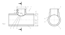
- Fig. 1 shows a welded T-fitting 1 in which the branching pipe 3 is at a 90 ° angle to the main line 2 and perpendicular to the main line 2 is joined together.
- the diameter d2 of the branch 3 does not correspond to the diameter d1 of the main line 2.
- pipes 2, 3 in Fig.1 welded together which have different diameters d1, d2.
- the wall thicknesses e1, e3 are approximately the same thickness in the region of the weld, resulting in the same joining pressure conditions.
- increased strength is given by the widespread wall thickness.
- a longitudinal section of a T-fitting 1 is shown in which the tubes to be welded together 2, 3 have the same diameter d1, d2, which is why the penetration curve 4, two converging in the apex 9 straight line corresponds. Since pointed converging straight lines or welding contours are not ideal in order to achieve high compressive strength, the apex 9 is rounded by a radius Ra2.
- the radius Ra2 corresponds to one-tenth of the same-sized pipe diameter d1, d2 or one fifth of the radius Ra1.
- the welding along the approximate penetration curve 5 also ensures in this embodiment of the T-fitting 1 with the same pipe diameter d1, d2 better compressive strength than is known from the prior art.
- FIG. 3 represents an amplified T-fitting 1, wherein the tubes 7, 8 are pushed over the pipes to be welded before 2, 3 and then the contours of the approaching fürdringungskurve 5 on the tubes 2, 3 and at the same time in the same operation on the slipped reinforcing tubes. 7 8 are milled. Due to the reinforcements, an additional increase in compressive strength is achieved.
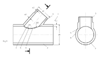
- Fig. 4 shows a T-fitting 1 in which the pipes to be welded 2, 3 are not joined together at a 90 ° angle. Also in such T-fittings, in which the tubes are joined together at any angle, is welded along the approximate penetration curve 5 and the tubes accordingly prepared or attached the appropriate contour.
- the branch 3 or the end face of the branch 3 as well as the cutout of the main line 2 have the corresponding contour of the approaching penetration curve 5 in order to subsequently join them together.
- the contour can not be defined by only one radius, but at least two radii Ra4, Ra5 are necessary to define an approximate penetration curve 5, along which the tubes 2.3 be welded.
- the theoretically determined penetration curve specifies the approximate course of the approximate penetration curve. By defined radii, such as Ra4 and Ra5, which are placed on the theoretical mondringungskurve, the approximate fürdringungskurve arises.
- FIG. 5 the individual steps of the manufacturing process of a welded T-fitting 1 are shown.
- the first figure illustrates the attachment, preferably by milling, the approximate fürdringungskurve 5 to the front of the branch 3 and the production of the recess in the main line 2 of the contour of the approximate fürdringungskurve 5.
- pipes 2, 3 by the over pushed tubes 7, 8 have a gain.
- the milling of the tubes 2, 3, 7, 8 need not be as in Fig.
- the branch 3 and the main line 2 can also be processed separately and are treated in parallel only during the welding process or heating.
- the heating of the contour of the approximate penetration curve 5 by means of a heating mirror 10 which also has the shape or contour of the approximate penetration curve 5.
- one side of the heating mirror 10 is preferably formed such that the approximate penetration curve 5 of the end face of the branch 3 can optimally abut it to allow optimum heat transfer. This means that as far as possible no free spaces or cavities between the heating mirror 10 and the contact surface of the pipe to be welded 2, 3, 7, 8 arise.
- the other side of the heating mirror 10 has the shape of the contour of the recess of the main line 2, to there also a good heat transfer To achieve complete concern of the heating mirror 10.
- a heating mirror 10 which has both contours, it is possible for the heating of both tubes to be carried out simultaneously with only one heating mirror 10. Ideal for this is the use of a flexible heating mat. After the heating phase, the heating mirror is removed and the two tubes 2, 3 including reinforcement 7, 8 pressed together, whereby the weld along the approximate penetration curve 5 is formed.
Landscapes
- Engineering & Computer Science (AREA)
- Mechanical Engineering (AREA)
- General Engineering & Computer Science (AREA)
- Lining Or Joining Of Plastics Or The Like (AREA)
Abstract
Description
- Die Erfindung betrifft ein geschweisstes T-Fitting aus thermoplastischem Kunststoff sowie ein Verfahren zu dessen Herstellung.
- T-Fittings werden in Rohrleitung zur Erzeugung von Rohrabgängen bzw. Abzweigungen eingesetzt. Aus Gewichts- und Korrosionsgründen wird im Rohrleitungsbau vermehrt thermoplastischer Kunststoff verwendet. Vorzugsweise werden Fluide wie bspw. Gas, Wasser, Abwasser oder auch Chemikalien in solchen Leitungen transportiert.
- Aus dem Stand der Technik sind unterschiedliche Verfahren zur Herstellung von T-Fittings aus Kunststoff bekannt.
In der Regel werden T-Fittings durch das Spritzgiessverfahren hergestellt. Dieses eignet sich vor allem für Rohrleitungen bzw. T-Fittings die eine bestimmte Dimension nicht überschreiten. Da einerseits die Wirtschaftlichkeit dieses Verfahrens erst ab einer gewissen Stückzahl der herzustellenden Fittings gegeben ist was bei grösseren Dimensionen selten der Fall ist und andererseits stösst man auch ab einer gewissen Wandstärkendimension rheologisch an die Grenzen der Machbarkeit. Das Spritzgiessverfahren eignet sich für grosse Dimensionen nur bedingt. - Die
US 5'551'733 offenbart ein T-Fitting, welches durch das Spritzgiessverfahren hergestellt wurde. Zur Verstärkung des Fittings wurden entlang der Mantelfläche kreuzartige Streben angebracht, die direkt in die Gussform mit eingearbeitet wurden. Dadurch erhält das T-Fitting eine höhere Steifigkeit und ermöglicht eine höhere Druckbelastbarkeit. - Ein weiteres Verfahren zur Herstellung eines Kunststoff-T-Fittings besteht darin, 45° schräg abgeschnittene Rohre miteinander zu verschweissen. Dazu werden zwei Schweissungen benötigt, was wiederum für die Druckbeständigkeit des T-Fittings von grossem Nachteil ist und dadurch mit einem Abminderungsfaktor der Druckbelastbarkeit von 0.6 gerechnet werden muss. Um diesen Abminderungsfaktor zu kompensieren besteht die Möglichkeit eine zusätzliche Verstärkung anzubringen, was wiederum mit hohen Kosten und grossem Aufwand verbunden ist.
- Aus dem Stand der Technik ist zur Herstellung eines geschweissten T-Fittings ein Verfahren bekannt, welches durch das Abdrehen einer Hohlstange an den beiden äusseren Enden die fluchtenden Stutzen bildet. In der Mitte der Hohlstange wird die Aussenkontur an einer Stelle entsprechend überfrässt um dort eine planare Auflagefläche zur Anschweissung des abgehenden Stutzens zu erzeugen. Die
EP 1 431 649 B1 offenbart ein solches Verfahren, wobei das dargestellte Verfahren durch einen zusätzlich montierten Verstärkungsring die Druckfestigkeit des T-Fittings erhöht.
Ein solches Verfahren bringt den Nachteil des hohen Materialverbrauchs durch die Überarbeitung der Hohlstange mit sich, sowie den zusätzlichen Aufwand des nachträglichen Anbringens einer Verstärkung. - Aufgabe der vorliegenden Erfindung ist es einer Vorrichtung und ein Verfahren vorzuschlagen, welches die Druckfestigkeit eines geschweissten T-Fittings erhöht ohne bei der Herstellung des Fittings viel Materialverlust zu generieren und ohne die Notwendigkeit zusätzlicher Verstärkungen.
- Diese Aufgabe wird erfindungsgemäss dadurch gelöst, dass die zusammenzufügenden Rohre entlang ihrer annähernden Durchdringungskurve verschweisst werden.
- Dadurch, dass die zusammenzufügenden Rohre entlang ihrer Durchdringungskurve verschweisst werden, verbessert sich die Druckbelastbarkeit. Die nach dem Stand der Technik geschweissten T-Fittings weisen einen Abminderungsfaktor der Druckbelastbarkeit von 0.6 auf. Durch das erfindungsgemässe Verfahren wird die Druckbelastbarkeit ohne Anbringen zusätzlichen Verstärkungen deutlich verbessert. Bei genauer Analyse hat sich gezeigt, dass es möglich ist die Rohre mit einer der Durchdringungskurve annähernden Kontur zu verschweissen und dass dadurch die Druckbelastbarkeit gegenüber einer Schweissnaht, die genau der Durchdringungskurve folgt nicht abnimmt.
Die annähernde Durchdringungskurve verläuft bei unterschiedlichen Rohrdurchmessern entlang der zusammenzuschweissenden Rohre vorzugsweise der Kontur des Radius der Hauptleitung und bei gleichen Rohrdurchmessenen der zusammenzuschweissenden Rohre der Durchdringungskurve, welche im Scheitelpunkt durch einen Radius verrundeten ist. - Der Verlauf dieser annähernden Durchdringungskurve entspricht der Kontur des Radius der Hauptleitung, das heisst, der Leitung bzw. des Rohrstücks an die das abgehende Rohr angeschweisst wird, wobei ausschliesslich bei Verschweissungen bei denen die miteinander zu verschweissenden Rohre unterschiedliche Durchmesser aufweisen. Im Falle, dass Rohre miteinander verschweisst werden, die denselben Durchmesser aufweisen, wird entlang der Durchdringungskurve geschweisst, wobei die Kurve nicht bis in den Scheitelpunkt verläuft sondern durch einen Radius verrundet ist, da spitz zusammenlaufende Konturen sich für druckbelastete Bauteile nicht eignen. Vorzugsweise wird zur Verrundung ein Radius verwendet der einem Fünftel des Radius der zusammenzuschweissenden Rohre entspricht.
- Damit die Rohre entlang ihrer annähernden Durchdringungskurve verschweisst werden können, wird an der Stelle ihrer Kontaktflächen, das heisst beim abzweigenden Rohr stirnseitig und bei der Hauptleitung in einer entsprechenden Aussparung eine Kontur angebracht, sei es durch fräsen oder sonst eine Bearbeitung, die der annähernden Durchdringungskurve entspricht.
- Um die Kontaktflächen auf die gewünschte Temperatur zu bringen, um anschliessend die Kunststoffrohre miteinander zu verschweissen, werden die Kontaktflächen an einem Heizspiegel erwärmt. Als Variante zum Heizspiegel ist es auch möglich eine flexible Heizmatte zu verwenden, die sich ideal der Kontur der annähernden Durchdringungskurve anschmiegt und dadurch das Erwärmen der Kontaktflächen gewährleistet. Bis zur Erreichung der gewünschten Temperatur bzw. Elastizität werden die Kontaktflächen in Berührung mit dem Heizspiegel bzw. der Heizmatte gehalten. Der Heizspiegel wie auch die Heizmatte muss zur optimalen Wärmeübertragung an der kompletten Kontaktfläche der Rohre anliegen. Die Erwärmung der beiden miteinander zu verschweissenden Rohre läuft vorzugsweise gleichzeitig ab. Zudem ist der Heizspiegel vorzugsweise so ausgestaltet, dass auf der einen Seite des Heizspiegels eine passende Kontur zur optimalen Berührung der Kontaktfläche des abzweigenden Rohres vorliegt und die gegenüberliegende Seite des Heizspiegels so ausgebildet ist, dass der Heizspiegel optimal an der Kontaktfläche der Aussparung der Hauptleitung anliegt.
Dadurch wird ermöglicht, dass die Kontaktflächen gleichzeitig mit nur einem Heizspiegel bzw. Heizmatte erwärmt werden. Dennoch ist auch eine Erwärmung der miteinander zu verschweissenden Kontaktflächen mit zwei separaten Heizspiegeln bzw. Heizmatten denkbar. Damit eine optimale Wärmeübertragung gewährleistet ist, muss der Heizspiegel die Kontur der annähernden Durchdringung der zu verschweissenden Rohre aufweisen, um entlang der gesamten Fläche der Kontur der annähernden Durchdringungskurve anzuliegen. - Ein solches Verfahren wir in der Regel erst bei Hauptrohrleitungsdurchmessern angewendet die mindestens 400 mm aufweisen, unabhängig von den Durchmessern der Abzweigungsanschlüssen.
- Vorzugsweise sind dir zu verschweissenden Rohre aus demselben Kunststoff, speziell gut eignet sich PE, PP, PB PA oder PVDF.
- Eine Ausgestaltung der Erfindung besteht darin, dass über die zusammenzuschweissenden Rohre als Verstärkung ein weiteres Rohr geschoben wird, an welches ebenfalls die Kontur der annähernden Durchdringungskurve gefräst wird, sowohl bei der Ausnehmung der Hauptleitung als auch an der Stirnseite des abzweigenden Rohres. Als weiteren Schritt werden die verstärkten Rohre an den Kontaktflächen mittels des Heizspiegels oder der Heizmatte erwärmt.
Die Verstärkung dient ebenso als Wandstärkenausgleich, das heisst, wenn die zu verschweissenden Rohre zu grosse Unterschiede bezüglich ihrer Wandstärke aufweisen, besteht die Möglichkeit, die Rohre die als Verstärkung eingesetzt werden entsprechend ihrer Wandstärke auszuwählen, um mehr oder weniger dieselben Wandstärken der verstärkten Rohre beim Verschweissen vorliegen zu haben. - Ausführungsbeispiele der Erfindung werden anhand der Figuren beschrieben, wobei sich die Erfindung nicht nur auf die Ausführungsbeispiele beschränkt. Es zeigen:
- Fig. 1
- einen Längsschnitt sowie eine Schnittansicht entsprechend der Schnittlinien eines geschweissten T-Fittings mit unterschiedlichen Rohrdurchmessern der zu verschweissenden Rohre,
- Fig. 2
- einen Längsschnitt sowie eine Schnittansicht entsprechend der Schnittlinien eines geschweissten T-Fittings mit gleichen Rohrdurchmesser der zu verschweissenden Rohre,
- Fig. 3
- einen Längsschnitt sowie eine Schnittansicht entsprechend der Schnittlinien eines geschweissten T-Fittings mit einer Verstärkung,
- Fig. 4
- einen Längsschnitt sowie eine Schnittansicht entsprechend der Schnittlinien eines geschweissten T-Fittings mit unterschiedlichen Rohrdurchmessern der zu verschweissenden Rohre, wobei das abzweigende Rohr nicht lotrecht von der Hauptleitung abzweigt und
- Fig. 5
- die einzelnen Produktionsschritte des Herstellverfahrens wobei die einzelnen Komponenten im Längsschnitt dargestellt sind.
-
Fig. 1 zeigt ein verschweisstes T-Fitting 1 bei welchem die abzweigende Rohrleitung 3 unter einem 90° Winkel zur Hauptleitung 2 verläuft bzw. lotrecht mit der Hauptleitung 2 zusammengefügt ist. Der Durchmesser d2 der Abzweigung 3 entspricht nicht dem Durchmesser d1 der Hauptleitung 2. Es werden demzufolge Rohre 2, 3 inFig.1 miteinander verschweisst, die unterschiedliche Durchmesser d1, d2 aufweisen. Zur Bildung einer guten Schweissnaht ist es von Vorteil, dass die Wandstärken e1, e3 im Bereich der Schweissnaht etwa gleich dick sind, wodurch gleiche Fügedruckverhältnisse entstehen. Zudem ist durch die verbreitete Wandstärke eine erhöhte Festigkeit gegeben. Deshalb ist es Vorteilhaft die Wandstärken der zusammenzufügenden Rohre anzugleichen bzw. anzupassen in dem bspw. eine Zunahme der Wandstärke e3 in der Abzweigung 3 vorgesehen ist, wie inFig. 1 dargestellt. Die theoretische Durchdringungskurve 4, die sich beim zusammenfügen der beiden Rohrleitungen 2, 3 ergeben würden, ist inFig. 1 durch die gestrichelte Linie 4 erkennbar. Die annähernde Durchdringungskurve 5 wird durch die Kontur des Radius Ra1 der dem Radius Ra1 der Hauptrohrleitung 2 entspricht erzielt. Das bringt den Vorteil mit sich, dass die annähernde Durchdringungskurve 5 einfach herzustellen ist und dieselbe Druckbelastbarkeit aufweist, wie wenn das Fitting 1 genau der Durchdringungskurve 4 entlang geschweisst werden würde. Die innere Durchdringungskurve 6 entsteht durch die Herstellung der annähernden Durchdringungskurve 5 und ergibt sich somit automatisch. Wie schon zuvor erwähnt wird durch das Verscheissen des T-Fittings 1 entlang der annähernden Durchdringungskurve 5 eine höhere Druckbelastbarkeit erreicht. Aus dem Stand der Technik waren bisher nur geschweisste T-Fittings bekannt, die nur einer Druckbelastbarkeit stand halten, die 0.6-mal der Druckbelastbarkeit auf die entsprechende Rohrdimension entspricht, da sie nicht einer annähernden Durchdringungskurve geschweisst werden sondern entlang gerade verlaufenden Kanten. Um eine höhere Druckbelastbarkeit zu erzielen mussten entsprechende Verstärkungen angebracht werden. Beim erfindungsgemässen Verfahren zur Herstellung eins T-Fittings ist eine höhere Druckbelastbarkeit gegeben da entlang der annährenden Durchdringungskurve 5 geschweisst wird. Zudem besteht ein weiterer Vorteil darin dass die annähernde Durchdringungskurve 5 durch eine einfache Teilkreiskontur herzustellen ist und trotzdem die hohe Druckbelastbarkeit erreicht.
InFig. 2 wird ein Längschnitt eines T-Fittings 1 dargestellt bei dem die miteinander zu verschweissenden Rohre 2, 3 denselben Durchmesser d1, d2 aufweisen, weshalb die Durchdringungskurve 4, zwei im Scheitelpunkt 9 zusammenlaufenden Geraden entspricht. Da spitz zusammenlaufende Geraden bzw. Schweiss-Konturen nicht ideal sind um eine hohe Druckbelastbarkeit zu erzielen, wird der Scheitelpunkt 9 durch einen Radius Ra2 verrundet. Der Radius Ra2 entspricht einem Zehntel der gleich dimensionierten Rohrdurchmesser d1, d2 bzw. einen Fünftel des Radius Ra1. Die Schweissung entlang der annähernden Durchdringungskurve 5 gewährleistet auch bei dieser Ausführungsform des T-Fittings 1 mit denselben Rohrdurchmesser d1, d2 einen bessere Druckbelastbarkeit als es aus dem Stand der Technik bekannt ist.
Fig. 3 stellt ein verstärktes T-Fitting 1 dar, wobei die Rohre 7, 8 zuvor über die zu verschweissenden Rohre 2, 3 geschoben werden und anschliessend die Konturen der annährenden Durchdringungskurve 5 an den Rohren 2, 3 sowie gleichzeitig im selben Arbeitsgang an den übergestülpten Verstärkungsrohren 7, 8 gefräst werden.
Durch die Verstärkungen wird eine zusätzliche Erhöhung der Druckbelastbarkeit erzielt.
Fig. 4 zeigt ein T-Fitting 1 bei dem die zu verschweissenden Rohre 2, 3 nicht unter einem 90° Winkel zusammengefügt werden. Auch bei solchen T-Fittings, bei denen die Rohre unter beliebigen Winkeln zusammengefügt werden, wird entlang der annähernden Durchdringungskurve 5 geschweisst und die Rohre entsprechend präpariert bzw. die entsprechende Kontur angebracht. Wodurch die Abzweigung 3 bzw. die Stirnfläche der Abzweigung 3 wie auch die Aussparung der Hauptleitung 2 die entsprechende Kontur der annährende Durchdringungskurve 5 aufweisen um sie anschiessend zusammenzufügen. Wobei die annähernde Durchdringungskurve 5, bei Rohren die nicht unter 90° zusammengeschweisst werden, sich die Kontur nicht durch nur einen Radius definieren lässt, sondern mindestens zwei Radien Ra4, Ra5 notwendig sind um eine annähernde Durchdringungskurve 5 festzulegen, entlang der die Rohre 2,3 verschweisst werden. Die theoretisch ermittelte Durchdringungskurve gibt den ungefähren Verlauf der annähernden Durchdringungskurve vor. Durch definierte Radien, wie Ra4 und Ra5, die an die theoretische Durchdringungskurve gelegt werden, entsteht die annähernde Durchdringungskurve. Ideal ist es dafür möglichst wenig aneinandergereihte Radien zu benötigen, jedoch ist es wichtig, dass die annähernde Durchdringungskurve nahe an der theoretischen Durchdringungskurve liegt.
InFig. 5 werden die einzelnen Schritte des Herstellverfahrens eines geschweissten T-Fittings 1 aufgezeigt. Die erste Abbildung verdeutlicht das Anbringen, vorzugsweise durch Fräsen, der annähernden Durchdringungskurve 5 an die Stirnseite der Abzweigung 3 sowie die Fertigung der Aussparung in der Hauptleitung 2 der Kontur der annähernden Durchdringungskurve 5. Wobei die inFig. 5 abgebildeten Rohre 2, 3 durch die darüber geschobenen Rohre 7, 8 eine Verstärkung aufweisen. Das Fräsen der Rohre 2, 3, 7,8 muss selbstverständlich nicht wie inFig. 5 dargestellt parallel verlaufen, die Abzweigung 3 sowie die Hauptleitung 2 können auch separat bearbeitet werden und werden erst beim Schweissprozess bzw. Erwärmen parallel behandelt. Anschliessen, dargestellt durch die zweite Abbildung, erfolgt das Erwärmen der Kontur der annähernden Durchdringungskurve 5, mittels eines Heizspiegels 10 der ebenfalls die Form bzw. Kontur der annähernden Durchdringungskurve 5 aufweist. Wobei die eine Seite des Heizspiegels 10 vorzugsweise derart ausgebildet ist, dass die annährende Durchdringungskurve 5 der Stirnseite der Abzweigung 3 optimal daran anliegen kann, um eine optimale Wärmeübertragung zu ermöglichen. Das heisst, dass möglichst keine Freiräume bzw. Hohlräume zwischen Heizspiegel 10 und der Kontaktfläche des zu verschweissenden Rohres 2, 3, 7, 8 entstehen. Zudem ist es von Vorteil, wenn die andere Seite des Heizspiegels 10 die Form der Kontur der Aussparung der Hauptleitung 2 aufweist, um auch dort eine gute Wärmeübertragung durch vollständiges Anliegen des Heizspiegels 10 zu erzielen. Ebenso wird durch einen Heizspiegel 10 der beide Konturen aufweist ermöglicht, dass die Erwärmung beider Rohre gleichzeitig mit nur einem Heizspiegel 10 durchgeführt werden kann. Ideal dafür ist auch der Einsatz einer biegbaren Heizmatte. Nach der Erwärmungsphase wird der Heizspiegel entfernt und die beiden Rohr 2, 3 inkl. Verstärkung 7, 8 zusammengepresst, wodurch die Schweissnaht entlang der annähernden Durchdringungskurve 5 entsteht. -
- 1
- T-Fitting
- 2
- Hauptleitung
- 3
- Abzweigung
- 4
- Durchdringungskurve
- 5
- Annähernde Durchdringungskurve
- 6
- Innere annähernde Durchdringungskurve
- 7
- Verstärkung
- 8
- Verstärkung
- 9
- Scheitelpunkt
- 10
- Heizspiegel
- 11
- Fräser
- d1
- Durchmesser Hauptrohrleitung
- d2
- Durchmesser Abzweigung
- e1
- Wandstärke Hauptleitung
- e2
- Wandstärke Abzweigung
- e3
- verbreiterte Wandstärke Abzweigung
- Ra1
- Radius der annähernden Durchdringungskurve bei T-Fitting mit ungleichen Rohrdurchmessern sowie Radius der Hauptleitung
- Ra2
- Verrundungsradius der annähernden Durchdringungskurve bei T-Fitting mit gleichen Rohrdurchmessern
- Ra3
- einer der Radien der annähernden Durchdringungskurve bei nicht lotrecht verschweissten Rohren
- Ra4
- einer der Radien der annähernden Durchdringungskurve bei nicht lotrecht verschweissten Rohren
Claims (15)
- Verfahren zur Herstellung eines geschweissten T-Fittings aus thermoplastischem Kunststoffe, dadurch gekennzeichnet, dass die zusammenzufügenden Rohre (2, 3) entlang ihrer annähernden Durchdringungskurve (5) verschweisst werden.
- Verfahren nach Anspruch 1, dadurch gekennzeichnet, dass die annähernde Durchdringungskurve (5) bei unterschiedlichen Rohrdurchmessern (d1, d2) der zusammenzuschweissenden Rohre (2, 3) vorzugsweise der Kontur des Radius (Ra1) der Hauptleitung (2) und bei gleichen Rohrdurchmessenen (d1, d2) der zusammenzuschweissenden Rohre (2, 3) der Durchdringungskurve (4), welche im Scheitelpunkt (9) durch einen Radius (Ra2) verrundeten ist, entspricht.
- Verfahren nach einem der Ansprüche 1 oder 2, dadurch gekennzeichnet, dass der Radius (Ra2) der Verrundung des Scheitelpunkts (9) einem Fünftel des Radius (Ra1) der zu verschweissenden Rohre (2, 3) entspricht.
- Verfahren nach einem der Ansprüche 1 bis 3, dadurch gekennzeichnet, dass an die zu verschweissenden Kontaktflächen der Rohre (2, 3) eine Kontur, die der annährenden Durchdringungskurve (5) der zusammenzufügenden Rohre (2, 3) entspricht, geformt wird.
- Verfahren nach einem der Ansprüche 1 bis 4, dadurch gekennzeichnet, dass das Erwärmen der Kontaktflächen mittels eines Heizspiegels (10) vorgenommen wird.
- Verfahren nach einem der Ansprüche 1 bis 5, dadurch gekennzeichnet, dass das Erwärmen der Kontaktflächen mittels einer flexiblen Heizmatte vorgenommen wird.
- Verfahren nach einem der Ansprüche 3 bis 6, dadurch gekennzeichnet, dass das Erwärmen der Kontaktflächen der miteinander zu verschweissenden Rohre (2, 3) gleichzeitig erfolgt.
- Verfahren nach einem der Ansprüche 4 oder 6, dadurch gekennzeichnet, dass der Heizspiegel (10) die Kontur der annähernden Durchdringungskurve (5) aufweist.
- Verfahren nach einem der Ansprüche 4 bis 7, dadurch gekennzeichnet, dass derselbe Heizspiegel (10) bzw. dieselbe flexible Heizmatte sowohl für die Kontur des abzweigenden Rohres (3) wie auch für die Kontaktflächen der Ausnehmung der Hauptleitung (2) eingesetzt wird.
- Verfahren nach einem der vorangehenden Ansprüche, dadurch gekennzeichnet dass, die Hauptleitung (2) einen Mindestaussendurchmesser (d1) von 400 mm aufweist.
- Verfahren nach einem der vorangehenden Ansprüche, dadurch gekennzeichnet, dass die zu verschweissenden Rohre (2, 3) aus demselben Kunststoff hergestellt sind vorzugsweise aus PE, PP, PB PA oder PVDF.
- Verfahren nach einem der vorangehenden Ansprüche, dadurch gekennzeichnet, dass eine Verstärkung (7, 8) der Wandstärke entlang des Umfangs der Rohre (2, 3) im Bereich der Schweissnaht angebracht wird.
- Verfahren nach Anspruch 12, dadurch gekennzeichnet, dass Rohre (7, 8) zur Verstärkung des T-Fittings (1) vor dem Verschweissen montiert werden.
- Verfahren nach Anspruch 13, dadurch gekennzeichnet, dass an die Rohre (7, 8) zur Verstärkung sowie an die Rohre (2, 3) der Hauptleitung oder Abzweigung (2,3) gleichzeitig im selben Arbeitsgang die Kontur der annähernden Durchdringungskurve gefräst wird.
- Geschweisster T-Fitting aus thermoplastischem Kunststoffe, dadurch gekennzeichnet, dass die zusammenzufügenden Rohre (2, 3) entlang ihrer annähernden Durchdringungskurve (5) geschweisst sind, wobei die annähernde Durchdringungskurve (5) bei unterschiedlichen Rohrdurchmessern (d1, d2) der zusammenzuschweissenden Rohre (2, 3) vorzugsweise der Kontur des Radius (Ra1) der Hauptleitung (2) und bei gleichen Rohrdurchmessenen (d1, d2) der zusammenzuschweissenden Rohre (2, 3) der Durchdringungskurve (4) welche im Scheitelpunkt (9) durch einen Radius (Ra2) verrundeten ist, entspricht.
Priority Applications (4)
| Application Number | Priority Date | Filing Date | Title |
|---|---|---|---|
| EP11182295A EP2573441A1 (de) | 2011-09-22 | 2011-09-22 | T-Fitting |
| RU2012137063/06A RU2012137063A (ru) | 2011-09-22 | 2012-08-30 | Т-образный фитинг |
| US13/623,496 US20130076022A1 (en) | 2011-09-22 | 2012-09-20 | Pipe tee |
| CN2012103537885A CN103016887A (zh) | 2011-09-22 | 2012-09-21 | 三通管 |
Applications Claiming Priority (1)
| Application Number | Priority Date | Filing Date | Title |
|---|---|---|---|
| EP11182295A EP2573441A1 (de) | 2011-09-22 | 2011-09-22 | T-Fitting |
Publications (1)
| Publication Number | Publication Date |
|---|---|
| EP2573441A1 true EP2573441A1 (de) | 2013-03-27 |
Family
ID=44674548
Family Applications (1)
| Application Number | Title | Priority Date | Filing Date |
|---|---|---|---|
| EP11182295A Withdrawn EP2573441A1 (de) | 2011-09-22 | 2011-09-22 | T-Fitting |
Country Status (4)
| Country | Link |
|---|---|
| US (1) | US20130076022A1 (de) |
| EP (1) | EP2573441A1 (de) |
| CN (1) | CN103016887A (de) |
| RU (1) | RU2012137063A (de) |
Cited By (4)
| Publication number | Priority date | Publication date | Assignee | Title |
|---|---|---|---|---|
| CN104033684A (zh) * | 2014-06-11 | 2014-09-10 | 永高股份有限公司 | 热熔焊接式pe分集水器 |
| WO2018192696A1 (de) | 2017-04-20 | 2018-10-25 | Contitech Elastomer-Beschichtungen Gmbh | Flexibles isolationsmaterial |
| CN116604228A (zh) * | 2023-05-09 | 2023-08-18 | 宁波易焊智能科技有限公司 | 三通智能焊接方法 |
| CN116618965A (zh) * | 2023-06-06 | 2023-08-22 | 洛阳船舶材料研究所(中国船舶集团有限公司第七二五研究所) | 一种铜镍合金卡压式三通制造方法 |
Families Citing this family (6)
| Publication number | Priority date | Publication date | Assignee | Title |
|---|---|---|---|---|
| CN103398258B (zh) * | 2013-07-04 | 2015-06-03 | 广东联塑科技实业有限公司 | 一种缓解塑料三通管件内相贯线应力集中的结构 |
| CN105465528B (zh) * | 2016-01-29 | 2019-12-31 | 四川新明塑业有限公司 | 一种大口径塑料三通管的制作方法 |
| US10392765B1 (en) * | 2018-04-02 | 2019-08-27 | Jeremy Hohnbaum | Flap gate drainage systems |
| CN112404888A (zh) * | 2020-09-23 | 2021-02-26 | 浙江德利福科技股份有限公司 | 一种不锈钢三通管的成型工艺 |
| US11345094B1 (en) * | 2021-04-02 | 2022-05-31 | Andrew J. Mayer | Sidewall fusion method for fusing branch outlets to host plastic pipe and apparatus for use therein |
| CN116021127A (zh) * | 2022-12-01 | 2023-04-28 | 航天工程装备(苏州)有限公司 | 一种三通及其制作方法 |
Citations (5)
| Publication number | Priority date | Publication date | Assignee | Title |
|---|---|---|---|---|
| DE1019516B (de) * | 1954-04-07 | 1957-11-14 | Esslingen Maschf | Schweissverbindung von Rohren mit zylindrischen Gefaessen |
| GB1147385A (en) * | 1966-01-21 | 1969-04-02 | Hans Keller | Pipe branch pieces and methods for making the same |
| DE1911194A1 (de) * | 1969-03-05 | 1970-09-24 | Kunststoffwerk Hoehn Gmbh | Verfahren zum nachtraeglichen Verstaerken von Abzweigstuecken fuer Rohrleitungen aus thermoplastischen Kunststoffen |
| US5551733A (en) | 1992-07-13 | 1996-09-03 | Vindex Tubemakers Pty. Limited | Plastic pipe branch fitting with reinforcing ribs |
| EP1431649B1 (de) | 2002-12-18 | 2008-04-02 | REINERT. RITZ GmbH | T-Stück aus Kunststoff |
Family Cites Families (4)
| Publication number | Priority date | Publication date | Assignee | Title |
|---|---|---|---|---|
| US4174248A (en) * | 1975-10-14 | 1979-11-13 | Phillips Petroleum Company | Process and apparatus for connecting plastic pipes |
| FR2690036B1 (fr) * | 1992-04-10 | 1998-10-09 | Gaz De France | Filet formant resistance, son application au soudage de tubes aboutes et au raccordement transversal de canalisations, ensembles ainsi constitues et prise de branchement electrosoudable ainsi equipee. |
| US6047757A (en) * | 1998-03-10 | 2000-04-11 | Global Utility Technologies Ltd. | Angled sidewall fusing apparatus |
| ITMI20012257A1 (it) * | 2001-10-26 | 2003-04-26 | Nupi S P A | Tubo multistrato con estremita' saldabile testa a testa e metodo di saldatura di un tubo multistrato |
-
2011
- 2011-09-22 EP EP11182295A patent/EP2573441A1/de not_active Withdrawn
-
2012
- 2012-08-30 RU RU2012137063/06A patent/RU2012137063A/ru not_active Application Discontinuation
- 2012-09-20 US US13/623,496 patent/US20130076022A1/en not_active Abandoned
- 2012-09-21 CN CN2012103537885A patent/CN103016887A/zh active Pending
Patent Citations (5)
| Publication number | Priority date | Publication date | Assignee | Title |
|---|---|---|---|---|
| DE1019516B (de) * | 1954-04-07 | 1957-11-14 | Esslingen Maschf | Schweissverbindung von Rohren mit zylindrischen Gefaessen |
| GB1147385A (en) * | 1966-01-21 | 1969-04-02 | Hans Keller | Pipe branch pieces and methods for making the same |
| DE1911194A1 (de) * | 1969-03-05 | 1970-09-24 | Kunststoffwerk Hoehn Gmbh | Verfahren zum nachtraeglichen Verstaerken von Abzweigstuecken fuer Rohrleitungen aus thermoplastischen Kunststoffen |
| US5551733A (en) | 1992-07-13 | 1996-09-03 | Vindex Tubemakers Pty. Limited | Plastic pipe branch fitting with reinforcing ribs |
| EP1431649B1 (de) | 2002-12-18 | 2008-04-02 | REINERT. RITZ GmbH | T-Stück aus Kunststoff |
Cited By (5)
| Publication number | Priority date | Publication date | Assignee | Title |
|---|---|---|---|---|
| CN104033684A (zh) * | 2014-06-11 | 2014-09-10 | 永高股份有限公司 | 热熔焊接式pe分集水器 |
| WO2018192696A1 (de) | 2017-04-20 | 2018-10-25 | Contitech Elastomer-Beschichtungen Gmbh | Flexibles isolationsmaterial |
| DE102017206654A1 (de) | 2017-04-20 | 2018-10-25 | Contitech Elastomer-Beschichtungen Gmbh | Flexibles Isolationsmaterial |
| CN116604228A (zh) * | 2023-05-09 | 2023-08-18 | 宁波易焊智能科技有限公司 | 三通智能焊接方法 |
| CN116618965A (zh) * | 2023-06-06 | 2023-08-22 | 洛阳船舶材料研究所(中国船舶集团有限公司第七二五研究所) | 一种铜镍合金卡压式三通制造方法 |
Also Published As
| Publication number | Publication date |
|---|---|
| RU2012137063A (ru) | 2014-03-10 |
| US20130076022A1 (en) | 2013-03-28 |
| CN103016887A (zh) | 2013-04-03 |
Similar Documents
| Publication | Publication Date | Title |
|---|---|---|
| EP2670664B1 (de) | Gebogenes doppelwandiges rohr und herstellungsverfahren des gebogenen doppelwandigen rohres | |
| EP2489918B1 (de) | Modulares Fitting | |
| EP3448653B1 (de) | Einfüllrohr für einen kraftstofftank | |
| WO2016005128A1 (de) | Rohrkupplung | |
| DE102009049941A1 (de) | Rohrstück und daraus gebildete Kapillarrohrmatte | |
| EP2958731B1 (de) | Vorrichtung und verfahren zur herstellung von kunststoffrohren | |
| DE1030124B (de) | Leitungsrohr aus Kunststoff und Verfahren zu seiner Herstellung | |
| DE69510770T2 (de) | Rohrverbindung und Verfahren zur seiner Herstellung | |
| EP1650486B1 (de) | T-Stück | |
| DE69921187T2 (de) | Verfahren zum herstellen einer anordnung zur verbindung von doppelwandigen kunststoffrohren | |
| DE2650371A1 (de) | Kupplungsrohrteil aus kunststoff und verfahren zu seiner herstellung | |
| DE10259143B3 (de) | T-Stück | |
| DE10138600B4 (de) | Anordnung sowie Verfahren zum Tiefziehen von Kunststoff-Metall-Kunststoff-Mehrschichtrohren | |
| DE3404294C1 (de) | Rohrteil aus einem thermoplastischen Kunststoff | |
| DE102014111381B4 (de) | Verfahren zur Nachumhüllung eines Rohrformteils | |
| EP2878429B1 (de) | Kunststoffformteil | |
| DE102007056822B4 (de) | Rohrabzweigelement aus Kunststoff und Verfahren zur Herstellung | |
| DE10358845B4 (de) | Verfahren zum Herstellen von kurzen gebogenen Rohrstücken | |
| DE2363727A1 (de) | Schweissbare rohrfittings aus kunststoff | |
| EP1859874B1 (de) | Schwimmer zur Herstellung von mindestens einwandigen Sicherheitsrohren, diese insbesondere zur Verwendung als Bremsleitungen, sowie Verfahren zur Herstellung eines solchen Schwimmers | |
| AT518536B1 (de) | Rohr mit Bund und Losflansch | |
| DE202004013061U1 (de) | Spritzgussteil zur Herstellung einer Rohrleitung | |
| DE10043824A1 (de) | Verfahren zur Verbindung dünnwandiger Rohre und Verbindung dünnwandiger Rohre | |
| DE3034592A1 (de) | Armaturenkappen-bausatz | |
| DE7345296U (de) | Schweissbarer rohrfitting aus kunststoff |
Legal Events
| Date | Code | Title | Description |
|---|---|---|---|
| PUAI | Public reference made under article 153(3) epc to a published international application that has entered the european phase |
Free format text: ORIGINAL CODE: 0009012 |
|
| AK | Designated contracting states |
Kind code of ref document: A1 Designated state(s): AL AT BE BG CH CY CZ DE DK EE ES FI FR GB GR HR HU IE IS IT LI LT LU LV MC MK MT NL NO PL PT RO RS SE SI SK SM TR |
|
| AX | Request for extension of the european patent |
Extension state: BA ME |
|
| 17P | Request for examination filed |
Effective date: 20130927 |
|
| RBV | Designated contracting states (corrected) |
Designated state(s): AL AT BE BG CH CY CZ DE DK EE ES FI FR GB GR HR HU IE IS IT LI LT LU LV MC MK MT NL NO PL PT RO RS SE SI SK SM TR |
|
| RIC1 | Information provided on ipc code assigned before grant |
Ipc: F16L 47/32 20060101AFI20131021BHEP |
|
| GRAP | Despatch of communication of intention to grant a patent |
Free format text: ORIGINAL CODE: EPIDOSNIGR1 |
|
| INTG | Intention to grant announced |
Effective date: 20140117 |
|
| STAA | Information on the status of an ep patent application or granted ep patent |
Free format text: STATUS: THE APPLICATION IS DEEMED TO BE WITHDRAWN |
|
| 18D | Application deemed to be withdrawn |
Effective date: 20140528 |