EP2573464A2 - Sections de combustion de turbines à gaz avec des assemblages d'écrans convectifs - Google Patents
Sections de combustion de turbines à gaz avec des assemblages d'écrans convectifs Download PDFInfo
- Publication number
- EP2573464A2 EP2573464A2 EP12175214A EP12175214A EP2573464A2 EP 2573464 A2 EP2573464 A2 EP 2573464A2 EP 12175214 A EP12175214 A EP 12175214A EP 12175214 A EP12175214 A EP 12175214A EP 2573464 A2 EP2573464 A2 EP 2573464A2
- Authority
- EP
- European Patent Office
- Prior art keywords
- case
- liner
- combustion
- section
- air
- Prior art date
- Legal status (The legal status is an assumption and is not a legal conclusion. Google has not performed a legal analysis and makes no representation as to the accuracy of the status listed.)
- Granted
Links
- 238000002485 combustion reaction Methods 0.000 title claims abstract description 86
- 230000000712 assembly Effects 0.000 title description 5
- 238000000429 assembly Methods 0.000 title description 5
- 239000000446 fuel Substances 0.000 claims abstract description 24
- 239000000203 mixture Substances 0.000 claims abstract description 8
- 238000012546 transfer Methods 0.000 claims description 10
- 239000007789 gas Substances 0.000 description 18
- 238000001816 cooling Methods 0.000 description 3
- RTAQQCXQSZGOHL-UHFFFAOYSA-N Titanium Chemical compound [Ti] RTAQQCXQSZGOHL-UHFFFAOYSA-N 0.000 description 2
- 239000000567 combustion gas Substances 0.000 description 2
- 230000008878 coupling Effects 0.000 description 2
- 238000010168 coupling process Methods 0.000 description 2
- 238000005859 coupling reaction Methods 0.000 description 2
- 238000000605 extraction Methods 0.000 description 2
- 239000000463 material Substances 0.000 description 2
- 230000005855 radiation Effects 0.000 description 2
- 239000010936 titanium Substances 0.000 description 2
- 229910052719 titanium Inorganic materials 0.000 description 2
- 229910000851 Alloy steel Inorganic materials 0.000 description 1
- 229910000990 Ni alloy Inorganic materials 0.000 description 1
- 230000009286 beneficial effect Effects 0.000 description 1
- 230000008602 contraction Effects 0.000 description 1
- 238000013461 design Methods 0.000 description 1
- 238000011161 development Methods 0.000 description 1
- 238000010790 dilution Methods 0.000 description 1
- 239000012895 dilution Substances 0.000 description 1
- 239000012530 fluid Substances 0.000 description 1
- 238000009434 installation Methods 0.000 description 1
- 238000004519 manufacturing process Methods 0.000 description 1
- 230000007246 mechanism Effects 0.000 description 1
- 238000010791 quenching Methods 0.000 description 1
- 238000011160 research Methods 0.000 description 1
- 239000010959 steel Substances 0.000 description 1
- 230000008646 thermal stress Effects 0.000 description 1
- 238000011144 upstream manufacturing Methods 0.000 description 1
Images


Classifications
-
- F—MECHANICAL ENGINEERING; LIGHTING; HEATING; WEAPONS; BLASTING
- F23—COMBUSTION APPARATUS; COMBUSTION PROCESSES
- F23R—GENERATING COMBUSTION PRODUCTS OF HIGH PRESSURE OR HIGH VELOCITY, e.g. GAS-TURBINE COMBUSTION CHAMBERS
- F23R3/00—Continuous combustion chambers using liquid or gaseous fuel
- F23R3/002—Wall structures
Definitions
- the following description generally relates to gas turbine engines, and more particularly relates to temperature control of cases within the combustion section of gas turbine engines.
- a gas turbine engine may be used to power various types of vehicles and systems.
- a particular type of gas turbine engine that may be used to power aircraft is a turbofan gas turbine engine.
- a turbofan gas turbine engine conventionally includes, for example, five major sections: a fan section, a compressor section, a combustor section, a turbine section, and an exhaust section.
- the fan section is typically positioned at the inlet section of the engine and includes a fan that induces air from the surrounding environment into the engine and accelerates a fraction of this air toward the compressor section. The remaining fraction of air induced into the fan section is accelerated into and through a bypass plenum and out the exhaust section.
- the compressor section raises the pressure of the air it receives from the fan section, and the resulting compressed air then enters the combustor section, where a ring of fuel nozzles injects a steady stream of fuel into a combustion chamber formed between inner and outer liners.
- the fuel and air mixture is ignited to form combustion gases, which drive rotors in the turbine section for power extraction.
- the gases then exit the engine at the exhaust section.
- Known combustors include inner and outer liners positioned within inner and outer cases.
- the inner and outer liners define an annular combustion chamber in which the fuel and air mixture is combusted.
- the inner liner and inner case define an inner plenum adjacent to one side of the combustion chamber, and the outer liner and outer case define an outer plenum adjacent to the other side of the combustion chamber.
- a portion of the airflow entering the combustion section is channeled through the plenums in an attempt to cool the liners and to subsequently enter the combustion chamber through the liners.
- the temperature of the plenum air may cause issues for the cases surrounding the liners. Over time, these elevated temperatures relative to the cases may result in thermal stresses and strains and other issues in the cases.
- a combustion section for a gas turbine engine.
- the combustion section includes a first liner; a second liner forming a combustion chamber with the first liner, the combustion chamber configured to receive an air-fuel mixture for combustion therein; a first case circumscribing the first liner and forming a first plenum with the first liner; and a convection shield assembly positioned between the first liner and the first case.
- an engine section includes combustion section with a first combustion liner; and a second combustion liner forming a combustion chamber with the first combustion liner, the combustion chamber configured to receive an air-fuel mixture for combustion therein; a turbine section configured to receive combustion gases produced within the combustion chamber; a first case circumscribing the first combustion liner and at least a portion of the turbine section, the first case forming a first plenum with the first combustion liner and the turbine section; and a convection shield assembly positioned between the first combustion liner and turbine section and the first case.
- FIG. 1 is a cross-sectional view of a gas turbine engine in accordance with an exemplary embodiment
- FIG. 2 is a cross-sectional view of an engine section in the gas turbine engine of FIG. 1 in accordance with an exemplary embodiment
- FIG. 3 is a cross-sectional view of an outer convection shield assembly and outer case of the engine section of FIG. 2 in accordance with an exemplary embodiment
- FIG. 4 is a partial, more-detailed cross-sectional view of the outer convection shield assembly and outer case of FIG. 3 in accordance with an exemplary embodiment.
- a combustion section includes a convection shield assembly interposed between the outer combustor case and the outer combustor liner.
- the convection shield assembly protects the combustor case from the high temperature air flowing through the plenums during operation.
- FIG. 1 is a cross-sectional view of a gas turbine engine 100 according to an exemplary embodiment.
- the gas turbine engine 100 can form part of, for example, an auxiliary power unit for an aircraft or a propulsion system for an aircraft.
- the gas turbine engine 100 may be disposed in an engine nacelle 110 and may include a fan section 120, a compressor section 130, a combustion section 140, a turbine section 150, and an exhaust section 160.
- the fan section 120 may include a fan 122, which draws in and accelerates air. A fraction of the accelerated air exhausted from the fan 122 is directed through a bypass section 170 to provide a forward thrust. The remaining fraction of air exhausted from the fan 122 is directed into the compressor section 130.
- the compressor section 130 may include a series of compressors 132, which raise the pressure of the air directed into it from the fan 122.
- the compressors 132 may direct the compressed air into the combustion section 140.
- the combustion section 140 which includes an annular combustor 208, the high pressure air is mixed with fuel and combusted. The combusted air is then directed into the turbine section 150.
- the combustion section 140 may include convection shield assemblies that protect combustor cases from the elevated temperatures associated with the air from the compressor section 130.
- the turbine section 150 may include a series of turbines 152, which may be disposed in axial flow series.
- the combusted air from the combustion section 140 expands through the turbines 152 and causes them to rotate.
- the air is then exhausted through a propulsion nozzle 162 disposed in the exhaust section 160, providing additional forward thrust.
- the turbines 152 rotate to thereby drive equipment in the gas turbine engine 100 via concentrically disposed shafts or spools.
- the turbines 152 may drive the compressor 132 via one or more shafts 154.
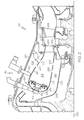
- FIG. 2 is a more detailed cross-sectional view of the combustion section 140 of FIG. 1 .
- a portion of the turbine section 150 is also shown downstream of the combustion section 140 (e.g., collectively forming an engine section).
- the depicted combustion section 140 is an annular-type combustion section, any other type of combustor, such as a can combustor, can be provided.
- the depicted combustion section 140 may be, for example, a rich burn, quick quench, lean burn (RQL) combustor section.
- the combustion section 140 comprises a radially inner case 202 and a radially outer case 204 concentrically arranged with respect to the inner case 202.
- the inner and outer cases 202 and 204 circumscribe the axially extending engine centerline 200 to define an annular pressure vessel 206.
- the combustion section 140 also includes the combustor 208 residing within the annular pressure vessel 206.
- the combustor 208 is defined by an outer liner 210 and an inner liner 212 that is circumscribed by the outer liner 210 to define an annular combustion chamber 214.
- the liners 210 and 212 cooperate with and are aligned relative to one another within cases 202 and 204 to define respective outer and inner air plenums 216 and 218.
- the outer liner 210 and outer case 204 define the outer plenum 216
- the inner liner 212 and the inner case 202 define the inner plenum 218.
- the inner liner 212 and outer liner 210 may be dual-walled liners or single-walled liners.
- the outer liner 210 and inner liner 212 may include one or more air admission holes 250 and 252 for admitting air into the combustion chamber 214 to support the combustion process.
- the outer liner 210 and inner liner 212 may further include effusion cooling holes for admitting a layer of air on the interior surfaces of the outer and inner liners 210 and 212 (e.g., within the combustion chamber 214).
- the combustor 208 additionally includes a front end assembly 220 with a shroud assembly 222, fuel injectors 224, and fuel injector guides 226.
- One fuel injector 224 and one fuel injector guide 226 are shown in the partial cross-sectional view of FIG. 2 .
- the combustor 208 includes a number of circumferentially distributed fuel injectors 224.
- Each fuel injector 224 is secured to the outer case 204 and projects through a shroud port 228.
- Each fuel injector 224 introduces a swirling, intimately blended fuel and air mixture that supports combustion in the combustion chamber 214.
- a fuel igniter 230 extends through the outer case 204 and the outer plenum 216 and is coupled to the outer liner 210.
- igniter 230 can be provided in the combustor 208, although only one is illustrated in FIG. 2 .
- the igniter 230 is arranged downstream from the fuel injector 224 and is positioned to ignite the fuel and air mixture within the combustion chamber 214.
- a flow of air from the compressor section 130 exits a high pressure diffuser and deswirler at a relatively high velocity and is directed into the annular pressure vessel 206 of the combustor 208.
- the compressed air flows through the plenums 216 and 218 and subsequently into the combustion chamber 214 through openings in the liners 210 and 212.
- a portion of the compressed air may enter the combustion chamber 214 at relatively upstream positions as primary air and another portion of the compressed air may enter the combustion chamber 214 at relatively downstream positions as dilution air.
- a portion of the air flowing through the plenums 216 and 218 may also be used to cool the liners 210 and 212.
- air flowing through the plenums 216 and 218 may be used for impingement and/or effusion cooling of the liners 210 and 212.
- the air in the combustion chamber 214 is mixed with fuel from the fuel injector 224 and combusted after being ignited by the igniter 230.
- the combusted air exits the combustion chamber 214 and is delivered to the turbine section 150.
- the turbine section 150 generally includes a turbine flow path for receiving the combustion air from the combustion chamber 214.
- the turbine flow path may be defined by inner platforms 262 and an outer turbine shroud 264 that radially confine the combustion air as it is directed through airfoils 266 for energy extraction.
- the outer case 204 and the outer plenum 216 additionally circumscribe at least a portion of the turbine section 150, for example, the turbine shroud 264.
- the combustion section 140 further includes convection shield assembly 270.
- a convection shield assembly 270 is mounted adjacent to the outer case 204 to protect the outer case 204 from the gases within the outer plenum 216.
- another (or inner) convection shield assembly may be mounted adjacent to the inner case 202 to protect the inner case 202 from the gases within the inner plenum 218
- the plenum air may still have a higher temperature than recommended for the case 204.
- the case 204 is titanium, and the plenum air may have temperatures of around 1000°F. Extended exposure to such temperatures may cause undesirable issues for some cases 204. This is particularly an issue with the plenum air, which may have high velocity, high density, and high pressure, thereby resulting in relatively high heat transfer coefficients.
- the convection shield assembly 270 provides protection for the case 202 from the plenum air.
- the convection shield assembly 270 may be formed from HASTX, Incone1718, or Incone11625.
- the convection shield assembly 270 isolates the case 204 from the plenum air to prevent convective heat transfer between the plenum air and the case 204.
- convective heat transfer is the transfer of heat from one component to another by the movement of fluids, such as air, which is in contrast to thermal radiation and/or conductive heat transfer.
- the combustion liners of the engine may be about 1200°F and the plenum air will be about 1000°F.
- the convection shield assembly isolates the case 204 from the plenum air to prevent convective heat transfer between the plenum air and the case 204.
- the convection shield assembly 270 also extends beyond the forward end of the turbine section 150 to protect the case 204 from the temperature of the plenum air in this section as well.
- the convection shield assembly 270 may enable the case 204 to maintain temperatures of more than 100°F or 200°F less than the temperature of the plenum air.
- the convection shield assembly 270 and case 204 may have a thermal resistance that is approximately two orders of magnitude greater than a case 204 has on its own.
- the manufacturing, design, and operating options for the combustion section 140 are enhanced.
- the case 204 may be manufactured from a lighter material, such as titanium, which may not otherwise have the durability characteristics of heavier materials, such as steel or nickel alloys.
- the combustion section 140 may be able to operate at higher temperatures than previous operating limits. Additional details of the shield assembly 270 are discussed below.
- FIG. 3 is a cross-sectional view of the convection shield assembly 270 and outer case 204 of the combustion section 140 of FIG. 2 in accordance with an exemplary embodiment.
- the outer case 204 generally extends in an axial direction and is typically an annular structure.
- a first end 302 includes a radial flange 304 for coupling to the compressor section 130 ( FIG. 1 ), and a second end 312 includes another radial flange 314 for coupling to the turbine section 150 ( FIG. 1 ).
- Openings 322 and 324 are defined in the outer case 204 to respectively accommodate the fuel injector 224 and fuel igniter 230 ( FIG. 2 ).
- Other flanges, protrusions, and/or openings may be provided as necessary or desired to accommodate other components of the combustion section 140.
- the convection shield assembly 270 has a shape that generally mirrors that of the outer case 204. As such, the convection shield assembly 270 generally extends in an axial direction and is typically an annular structure. In particular, the convection shield assembly 270 extends from a first (or forward) end 370 adjacent the first end 302 of the outer case 204 to a second (or aft) end 372 adjacent the second end 312 of the outer case 204. Additionally, the convection shield assembly 270 may have openings 382 and 384 that match the openings 322 and 324 in the outer case 204.
- the convection shield assembly 270 may be continuous except for portions that accommodate flanges, protrusions, and/or openings in the outer case 204. In other embodiments, the convection shield assembly 270 may be in sections or tiles.
- FIG. 4 is a partial, more-detailed cross-sectional view of the convection shield assembly 270 and outer case 204 of FIG. 3 in accordance with an exemplary embodiment.
- FIG. 4 is a view at the first end 302 of the outer case 204.
- the convection shield assembly 270 is offset from the outer case 204 by a distance 402.
- the distance 402 is relatively small, although sufficient to at least partially prevent convective heat transfer from the plenum air to the outer case 204.
- the distance 402 is greater than zero, although, for example, less than an inch, less than half an inch, or less than a tenth of an inch.
- the distance 402 may be, for example, about 0.02 inches. Due to the relatively small distance 402 between the outer case 204 and the convection shield assembly 270, the convection shield assembly 270 generally does not interfere with the aerodynamic properties of the plenum air and particularly does not interfere with the cooling arrangements for the liners 210.
- the convection shield assembly 270 may be mounted on the outer case 204 in any suitable manner.
- the convection shield assembly 270 is mounted on the outer case 204 with a bolt 410.
- the mounting arrangements may enable thermal growth or contraction of the convection shield assembly 270, particularly in an axial direction.
- Other installation mechanisms may also be provided.
- an axi-symmetric slot or local tabs may be provided at each end of the convection shield assembly 270 to cooperate with tabs or flanges in the case 204.
- exemplary embodiments discussed herein provide improved thermal management of the combustion sections of gas turbines engines.
- the convection shield assemblies enable operating conditions with higher temperatures and/or increased durability for the combustion cases in a cost-effective and reliable manner, for example, without complicated active mechanical arrangements and/or without heavy or expensive components.
- Different configurations and arrangements of the shield assemblies may be provided as necessary in dependence on the desired temperature of the respective case.
- an annular combustor section is described above, the convection shield assemblies may be used with other combustor arrangements, such as can combustors.
- Exemplary embodiments may find beneficial uses in many industries, including aerospace and particularly in high performance aircraft, as well as automotive and electrical generation.
Landscapes
- Engineering & Computer Science (AREA)
- Chemical & Material Sciences (AREA)
- Combustion & Propulsion (AREA)
- Mechanical Engineering (AREA)
- General Engineering & Computer Science (AREA)
- Turbine Rotor Nozzle Sealing (AREA)
Applications Claiming Priority (1)
| Application Number | Priority Date | Filing Date | Title |
|---|---|---|---|
| US13/237,685 US20130067932A1 (en) | 2011-09-20 | 2011-09-20 | Combustion sections of gas turbine engines with convection shield assemblies |
Publications (3)
| Publication Number | Publication Date |
|---|---|
| EP2573464A2 true EP2573464A2 (fr) | 2013-03-27 |
| EP2573464A3 EP2573464A3 (fr) | 2013-12-25 |
| EP2573464B1 EP2573464B1 (fr) | 2015-03-04 |
Family
ID=46508252
Family Applications (1)
| Application Number | Title | Priority Date | Filing Date |
|---|---|---|---|
| EP12175214.1A Not-in-force EP2573464B1 (fr) | 2011-09-20 | 2012-07-05 | Sections de combustion de turbines à gaz avec des assemblages d'écrans convectifs |
Country Status (2)
| Country | Link |
|---|---|
| US (1) | US20130067932A1 (fr) |
| EP (1) | EP2573464B1 (fr) |
Cited By (3)
| Publication number | Priority date | Publication date | Assignee | Title |
|---|---|---|---|---|
| US9957816B2 (en) | 2014-05-29 | 2018-05-01 | General Electric Company | Angled impingement insert |
| US10422235B2 (en) | 2014-05-29 | 2019-09-24 | General Electric Company | Angled impingement inserts with cooling features |
| US10690055B2 (en) | 2014-05-29 | 2020-06-23 | General Electric Company | Engine components with impingement cooling features |
Families Citing this family (3)
| Publication number | Priority date | Publication date | Assignee | Title |
|---|---|---|---|---|
| EP3181866B1 (fr) * | 2015-12-16 | 2018-07-04 | Airbus Operations, S.L. | Moteur à turbine à gaz pour un avion |
| US10711640B2 (en) * | 2017-04-11 | 2020-07-14 | Raytheon Technologies Corporation | Cooled cooling air to blade outer air seal passing through a static vane |
| US20180291760A1 (en) * | 2017-04-11 | 2018-10-11 | United Technologies Corporation | Cooling air chamber for blade outer air seal |
Family Cites Families (14)
| Publication number | Priority date | Publication date | Assignee | Title |
|---|---|---|---|---|
| US2670600A (en) * | 1947-06-17 | 1954-03-02 | Bristol Aeroplane Co Ltd | Air distribution system for flame tubes of gas turbine engines |
| US2676460A (en) * | 1950-03-23 | 1954-04-27 | United Aircraft Corp | Burner construction of the can-an-nular type having means for distributing airflow to each can |
| US2702454A (en) * | 1951-06-07 | 1955-02-22 | United Aircraft Corp | Transition piece providing a connection between the combustion chambers and the turbine nozzle in gas turbine power plants |
| US3722216A (en) * | 1971-01-04 | 1973-03-27 | Gen Electric | Annular slot combustor |
| US5165226A (en) * | 1991-08-09 | 1992-11-24 | Pratt & Whitney Canada, Inc. | Single vortex combustor arrangement |
| US5269468A (en) * | 1992-06-22 | 1993-12-14 | General Electric Company | Fuel nozzle |
| FR2723177B1 (fr) * | 1994-07-27 | 1996-09-06 | Snecma | Chambre de combustion comportant une double paroi |
| US5598696A (en) * | 1994-09-20 | 1997-02-04 | Parker-Hannifin Corporation | Clip attached heat shield |
| US5901548A (en) * | 1996-12-23 | 1999-05-11 | General Electric Company | Air assist fuel atomization in a gas turbine engine |
| US6149075A (en) * | 1999-09-07 | 2000-11-21 | General Electric Company | Methods and apparatus for shielding heat from a fuel nozzle stem of fuel nozzle |
| FR2885168A1 (fr) * | 2005-04-27 | 2006-11-03 | Snecma Moteurs Sa | Dispositif d'etancheite pour une enceinte d'une turbomachine, et moteur d'aeronef equipe de celui-ci |
| GB2432198B (en) * | 2005-11-15 | 2007-10-03 | Rolls Royce Plc | Sealing arrangement |
| US7500364B2 (en) * | 2005-11-22 | 2009-03-10 | Honeywell International Inc. | System for coupling flow from a centrifugal compressor to an axial combustor for gas turbines |
| GB2434199B (en) * | 2006-01-14 | 2011-01-05 | Alstom Technology Ltd | Combustor liner with heat shield |
-
2011
- 2011-09-20 US US13/237,685 patent/US20130067932A1/en not_active Abandoned
-
2012
- 2012-07-05 EP EP12175214.1A patent/EP2573464B1/fr not_active Not-in-force
Non-Patent Citations (1)
| Title |
|---|
| None |
Cited By (3)
| Publication number | Priority date | Publication date | Assignee | Title |
|---|---|---|---|---|
| US9957816B2 (en) | 2014-05-29 | 2018-05-01 | General Electric Company | Angled impingement insert |
| US10422235B2 (en) | 2014-05-29 | 2019-09-24 | General Electric Company | Angled impingement inserts with cooling features |
| US10690055B2 (en) | 2014-05-29 | 2020-06-23 | General Electric Company | Engine components with impingement cooling features |
Also Published As
| Publication number | Publication date |
|---|---|
| US20130067932A1 (en) | 2013-03-21 |
| EP2573464A3 (fr) | 2013-12-25 |
| EP2573464B1 (fr) | 2015-03-04 |
Similar Documents
| Publication | Publication Date | Title |
|---|---|---|
| EP2330350B1 (fr) | Chambres de combustion à double paroi dotées d'allumeurs refroidis par projection | |
| EP2325563B1 (fr) | Chambre de combustion à double paroi dotée de joint de revêtement amélioré | |
| EP3922829B1 (fr) | Chambre de combustion de turbine à gaz comprenant une chemise munie de trous de refroidissement à travers une structure transversale | |
| EP2971668B1 (fr) | Refroidissement actif de bossages d'oeillet pour un panneau de chambre de combustion d'un moteur à turbine à gaz | |
| EP3071816B1 (fr) | Refroidissement d'une structure à parois multiples d'un moteur à turbine | |
| US20140190171A1 (en) | Combustors with hybrid walled liners | |
| JP7109884B2 (ja) | ガスタービンの流れスリーブの取り付け | |
| EP3047128B1 (fr) | Variation contrôlée de la chute de pression par refroidissement par effusion dans une chambre de combustion à double paroi d'une turbine à gaz | |
| US20160201908A1 (en) | Vena contracta swirling dilution passages for gas turbine engine combustor | |
| EP2932070B1 (fr) | Bouclier thermique de chambre de combustion de moteur à turbine à gaz avec efficacité de refroidissement pelliculaire accrue | |
| US10655855B2 (en) | Gas turbine engine wall assembly with support shell contour regions | |
| US11112117B2 (en) | Fuel nozzle cooling structure | |
| EP2573464B1 (fr) | Sections de combustion de turbines à gaz avec des assemblages d'écrans convectifs | |
| EP3039346A1 (fr) | Passages de dilution profilés pour chambre à combustion de turbine à gaz | |
| US20100012750A1 (en) | Fuel nozzle centerbody and method of assembling the same | |
| US11662096B2 (en) | Combustor swirler to pseudo-dome attachment and interface with a CMC dome | |
| EP3643968B1 (fr) | Structure de section chaude à double paroi d'un moteur à turbine à gaz | |
| US11828466B2 (en) | Combustor swirler to CMC dome attachment | |
| EP2045527A2 (fr) | Ensembles de dôme à facettes pour chambres de combustion de turbines à gaz |
Legal Events
| Date | Code | Title | Description |
|---|---|---|---|
| PUAI | Public reference made under article 153(3) epc to a published international application that has entered the european phase |
Free format text: ORIGINAL CODE: 0009012 |
|
| 17P | Request for examination filed |
Effective date: 20120705 |
|
| AK | Designated contracting states |
Kind code of ref document: A2 Designated state(s): AL AT BE BG CH CY CZ DE DK EE ES FI FR GB GR HR HU IE IS IT LI LT LU LV MC MK MT NL NO PL PT RO RS SE SI SK SM TR |
|
| AX | Request for extension of the european patent |
Extension state: BA ME |
|
| PUAL | Search report despatched |
Free format text: ORIGINAL CODE: 0009013 |
|
| AK | Designated contracting states |
Kind code of ref document: A3 Designated state(s): AL AT BE BG CH CY CZ DE DK EE ES FI FR GB GR HR HU IE IS IT LI LT LU LV MC MK MT NL NO PL PT RO RS SE SI SK SM TR |
|
| AX | Request for extension of the european patent |
Extension state: BA ME |
|
| RIC1 | Information provided on ipc code assigned before grant |
Ipc: F23R 3/00 20060101AFI20131118BHEP Ipc: F01D 25/26 20060101ALI20131118BHEP |
|
| 17Q | First examination report despatched |
Effective date: 20131204 |
|
| GRAP | Despatch of communication of intention to grant a patent |
Free format text: ORIGINAL CODE: EPIDOSNIGR1 |
|
| INTG | Intention to grant announced |
Effective date: 20141016 |
|
| GRAS | Grant fee paid |
Free format text: ORIGINAL CODE: EPIDOSNIGR3 |
|
| GRAA | (expected) grant |
Free format text: ORIGINAL CODE: 0009210 |
|
| AK | Designated contracting states |
Kind code of ref document: B1 Designated state(s): AL AT BE BG CH CY CZ DE DK EE ES FI FR GB GR HR HU IE IS IT LI LT LU LV MC MK MT NL NO PL PT RO RS SE SI SK SM TR |
|
| REG | Reference to a national code |
Ref country code: GB Ref legal event code: FG4D |
|
| REG | Reference to a national code |
Ref country code: CH Ref legal event code: EP |
|
| REG | Reference to a national code |
Ref country code: IE Ref legal event code: FG4D |
|
| REG | Reference to a national code |
Ref country code: AT Ref legal event code: REF Ref document number: 714228 Country of ref document: AT Kind code of ref document: T Effective date: 20150415 |
|
| REG | Reference to a national code |
Ref country code: DE Ref legal event code: R096 Ref document number: 602012005500 Country of ref document: DE Effective date: 20150416 |
|
| REG | Reference to a national code |
Ref country code: AT Ref legal event code: MK05 Ref document number: 714228 Country of ref document: AT Kind code of ref document: T Effective date: 20150304 Ref country code: NL Ref legal event code: VDEP Effective date: 20150304 |
|
| PG25 | Lapsed in a contracting state [announced via postgrant information from national office to epo] |
Ref country code: HR Free format text: LAPSE BECAUSE OF FAILURE TO SUBMIT A TRANSLATION OF THE DESCRIPTION OR TO PAY THE FEE WITHIN THE PRESCRIBED TIME-LIMIT Effective date: 20150304 Ref country code: SE Free format text: LAPSE BECAUSE OF FAILURE TO SUBMIT A TRANSLATION OF THE DESCRIPTION OR TO PAY THE FEE WITHIN THE PRESCRIBED TIME-LIMIT Effective date: 20150304 Ref country code: ES Free format text: LAPSE BECAUSE OF FAILURE TO SUBMIT A TRANSLATION OF THE DESCRIPTION OR TO PAY THE FEE WITHIN THE PRESCRIBED TIME-LIMIT Effective date: 20150304 Ref country code: NO Free format text: LAPSE BECAUSE OF FAILURE TO SUBMIT A TRANSLATION OF THE DESCRIPTION OR TO PAY THE FEE WITHIN THE PRESCRIBED TIME-LIMIT Effective date: 20150604 Ref country code: LT Free format text: LAPSE BECAUSE OF FAILURE TO SUBMIT A TRANSLATION OF THE DESCRIPTION OR TO PAY THE FEE WITHIN THE PRESCRIBED TIME-LIMIT Effective date: 20150304 Ref country code: FI Free format text: LAPSE BECAUSE OF FAILURE TO SUBMIT A TRANSLATION OF THE DESCRIPTION OR TO PAY THE FEE WITHIN THE PRESCRIBED TIME-LIMIT Effective date: 20150304 |
|
| REG | Reference to a national code |
Ref country code: LT Ref legal event code: MG4D |
|
| PG25 | Lapsed in a contracting state [announced via postgrant information from national office to epo] |
Ref country code: LV Free format text: LAPSE BECAUSE OF FAILURE TO SUBMIT A TRANSLATION OF THE DESCRIPTION OR TO PAY THE FEE WITHIN THE PRESCRIBED TIME-LIMIT Effective date: 20150304 Ref country code: AT Free format text: LAPSE BECAUSE OF FAILURE TO SUBMIT A TRANSLATION OF THE DESCRIPTION OR TO PAY THE FEE WITHIN THE PRESCRIBED TIME-LIMIT Effective date: 20150304 Ref country code: GR Free format text: LAPSE BECAUSE OF FAILURE TO SUBMIT A TRANSLATION OF THE DESCRIPTION OR TO PAY THE FEE WITHIN THE PRESCRIBED TIME-LIMIT Effective date: 20150605 Ref country code: RS Free format text: LAPSE BECAUSE OF FAILURE TO SUBMIT A TRANSLATION OF THE DESCRIPTION OR TO PAY THE FEE WITHIN THE PRESCRIBED TIME-LIMIT Effective date: 20150304 |
|
| PG25 | Lapsed in a contracting state [announced via postgrant information from national office to epo] |
Ref country code: NL Free format text: LAPSE BECAUSE OF FAILURE TO SUBMIT A TRANSLATION OF THE DESCRIPTION OR TO PAY THE FEE WITHIN THE PRESCRIBED TIME-LIMIT Effective date: 20150304 |
|
| PG25 | Lapsed in a contracting state [announced via postgrant information from national office to epo] |
Ref country code: SK Free format text: LAPSE BECAUSE OF FAILURE TO SUBMIT A TRANSLATION OF THE DESCRIPTION OR TO PAY THE FEE WITHIN THE PRESCRIBED TIME-LIMIT Effective date: 20150304 Ref country code: PT Free format text: LAPSE BECAUSE OF FAILURE TO SUBMIT A TRANSLATION OF THE DESCRIPTION OR TO PAY THE FEE WITHIN THE PRESCRIBED TIME-LIMIT Effective date: 20150706 Ref country code: EE Free format text: LAPSE BECAUSE OF FAILURE TO SUBMIT A TRANSLATION OF THE DESCRIPTION OR TO PAY THE FEE WITHIN THE PRESCRIBED TIME-LIMIT Effective date: 20150304 Ref country code: RO Free format text: LAPSE BECAUSE OF FAILURE TO SUBMIT A TRANSLATION OF THE DESCRIPTION OR TO PAY THE FEE WITHIN THE PRESCRIBED TIME-LIMIT Effective date: 20150304 Ref country code: CZ Free format text: LAPSE BECAUSE OF FAILURE TO SUBMIT A TRANSLATION OF THE DESCRIPTION OR TO PAY THE FEE WITHIN THE PRESCRIBED TIME-LIMIT Effective date: 20150304 |
|
| PG25 | Lapsed in a contracting state [announced via postgrant information from national office to epo] |
Ref country code: PL Free format text: LAPSE BECAUSE OF FAILURE TO SUBMIT A TRANSLATION OF THE DESCRIPTION OR TO PAY THE FEE WITHIN THE PRESCRIBED TIME-LIMIT Effective date: 20150304 Ref country code: IS Free format text: LAPSE BECAUSE OF FAILURE TO SUBMIT A TRANSLATION OF THE DESCRIPTION OR TO PAY THE FEE WITHIN THE PRESCRIBED TIME-LIMIT Effective date: 20150704 |
|
| REG | Reference to a national code |
Ref country code: DE Ref legal event code: R097 Ref document number: 602012005500 Country of ref document: DE |
|
| RAP2 | Party data changed (patent owner data changed or rights of a patent transferred) |
Owner name: HONEYWELL INTERNATIONAL INC. |
|
| PG25 | Lapsed in a contracting state [announced via postgrant information from national office to epo] |
Ref country code: IT Free format text: LAPSE BECAUSE OF FAILURE TO SUBMIT A TRANSLATION OF THE DESCRIPTION OR TO PAY THE FEE WITHIN THE PRESCRIBED TIME-LIMIT Effective date: 20150304 |
|
| PLBE | No opposition filed within time limit |
Free format text: ORIGINAL CODE: 0009261 |
|
| STAA | Information on the status of an ep patent application or granted ep patent |
Free format text: STATUS: NO OPPOSITION FILED WITHIN TIME LIMIT |
|
| PG25 | Lapsed in a contracting state [announced via postgrant information from national office to epo] |
Ref country code: DK Free format text: LAPSE BECAUSE OF FAILURE TO SUBMIT A TRANSLATION OF THE DESCRIPTION OR TO PAY THE FEE WITHIN THE PRESCRIBED TIME-LIMIT Effective date: 20150304 |
|
| 26N | No opposition filed |
Effective date: 20151207 |
|
| PG25 | Lapsed in a contracting state [announced via postgrant information from national office to epo] |
Ref country code: MC Free format text: LAPSE BECAUSE OF FAILURE TO SUBMIT A TRANSLATION OF THE DESCRIPTION OR TO PAY THE FEE WITHIN THE PRESCRIBED TIME-LIMIT Effective date: 20150304 Ref country code: SI Free format text: LAPSE BECAUSE OF FAILURE TO SUBMIT A TRANSLATION OF THE DESCRIPTION OR TO PAY THE FEE WITHIN THE PRESCRIBED TIME-LIMIT Effective date: 20150304 |
|
| REG | Reference to a national code |
Ref country code: CH Ref legal event code: PL |
|
| PG25 | Lapsed in a contracting state [announced via postgrant information from national office to epo] |
Ref country code: LU Free format text: LAPSE BECAUSE OF FAILURE TO SUBMIT A TRANSLATION OF THE DESCRIPTION OR TO PAY THE FEE WITHIN THE PRESCRIBED TIME-LIMIT Effective date: 20150705 |
|
| REG | Reference to a national code |
Ref country code: IE Ref legal event code: MM4A |
|
| PG25 | Lapsed in a contracting state [announced via postgrant information from national office to epo] |
Ref country code: CH Free format text: LAPSE BECAUSE OF NON-PAYMENT OF DUE FEES Effective date: 20150731 Ref country code: LI Free format text: LAPSE BECAUSE OF NON-PAYMENT OF DUE FEES Effective date: 20150731 |
|
| REG | Reference to a national code |
Ref country code: FR Ref legal event code: ST Effective date: 20160331 |
|
| PG25 | Lapsed in a contracting state [announced via postgrant information from national office to epo] |
Ref country code: FR Free format text: LAPSE BECAUSE OF NON-PAYMENT OF DUE FEES Effective date: 20150731 |
|
| PG25 | Lapsed in a contracting state [announced via postgrant information from national office to epo] |
Ref country code: IE Free format text: LAPSE BECAUSE OF NON-PAYMENT OF DUE FEES Effective date: 20150705 |
|
| PG25 | Lapsed in a contracting state [announced via postgrant information from national office to epo] |
Ref country code: BE Free format text: LAPSE BECAUSE OF FAILURE TO SUBMIT A TRANSLATION OF THE DESCRIPTION OR TO PAY THE FEE WITHIN THE PRESCRIBED TIME-LIMIT Effective date: 20150304 |
|
| GBPC | Gb: european patent ceased through non-payment of renewal fee |
Effective date: 20160705 |
|
| PG25 | Lapsed in a contracting state [announced via postgrant information from national office to epo] |
Ref country code: MT Free format text: LAPSE BECAUSE OF FAILURE TO SUBMIT A TRANSLATION OF THE DESCRIPTION OR TO PAY THE FEE WITHIN THE PRESCRIBED TIME-LIMIT Effective date: 20150304 |
|
| PG25 | Lapsed in a contracting state [announced via postgrant information from national office to epo] |
Ref country code: SM Free format text: LAPSE BECAUSE OF FAILURE TO SUBMIT A TRANSLATION OF THE DESCRIPTION OR TO PAY THE FEE WITHIN THE PRESCRIBED TIME-LIMIT Effective date: 20150304 Ref country code: BG Free format text: LAPSE BECAUSE OF FAILURE TO SUBMIT A TRANSLATION OF THE DESCRIPTION OR TO PAY THE FEE WITHIN THE PRESCRIBED TIME-LIMIT Effective date: 20150304 Ref country code: HU Free format text: LAPSE BECAUSE OF FAILURE TO SUBMIT A TRANSLATION OF THE DESCRIPTION OR TO PAY THE FEE WITHIN THE PRESCRIBED TIME-LIMIT; INVALID AB INITIO Effective date: 20120705 Ref country code: GB Free format text: LAPSE BECAUSE OF NON-PAYMENT OF DUE FEES Effective date: 20160705 |
|
| PG25 | Lapsed in a contracting state [announced via postgrant information from national office to epo] |
Ref country code: CY Free format text: LAPSE BECAUSE OF FAILURE TO SUBMIT A TRANSLATION OF THE DESCRIPTION OR TO PAY THE FEE WITHIN THE PRESCRIBED TIME-LIMIT Effective date: 20150304 |
|
| PG25 | Lapsed in a contracting state [announced via postgrant information from national office to epo] |
Ref country code: TR Free format text: LAPSE BECAUSE OF FAILURE TO SUBMIT A TRANSLATION OF THE DESCRIPTION OR TO PAY THE FEE WITHIN THE PRESCRIBED TIME-LIMIT Effective date: 20150304 |
|
| PG25 | Lapsed in a contracting state [announced via postgrant information from national office to epo] |
Ref country code: MK Free format text: LAPSE BECAUSE OF FAILURE TO SUBMIT A TRANSLATION OF THE DESCRIPTION OR TO PAY THE FEE WITHIN THE PRESCRIBED TIME-LIMIT Effective date: 20150304 |
|
| PG25 | Lapsed in a contracting state [announced via postgrant information from national office to epo] |
Ref country code: AL Free format text: LAPSE BECAUSE OF FAILURE TO SUBMIT A TRANSLATION OF THE DESCRIPTION OR TO PAY THE FEE WITHIN THE PRESCRIBED TIME-LIMIT Effective date: 20150304 |
|
| PGFP | Annual fee paid to national office [announced via postgrant information from national office to epo] |
Ref country code: DE Payment date: 20190731 Year of fee payment: 8 |
|
| REG | Reference to a national code |
Ref country code: DE Ref legal event code: R119 Ref document number: 602012005500 Country of ref document: DE |
|
| PG25 | Lapsed in a contracting state [announced via postgrant information from national office to epo] |
Ref country code: DE Free format text: LAPSE BECAUSE OF NON-PAYMENT OF DUE FEES Effective date: 20210202 |
|
| P01 | Opt-out of the competence of the unified patent court (upc) registered |
Effective date: 20230525 |