EP2573465A2 - Brennkammer und Verfahren zur Konditionierung der Strömung durch eine Brennkammer - Google Patents
Brennkammer und Verfahren zur Konditionierung der Strömung durch eine Brennkammer Download PDFInfo
- Publication number
- EP2573465A2 EP2573465A2 EP12183805A EP12183805A EP2573465A2 EP 2573465 A2 EP2573465 A2 EP 2573465A2 EP 12183805 A EP12183805 A EP 12183805A EP 12183805 A EP12183805 A EP 12183805A EP 2573465 A2 EP2573465 A2 EP 2573465A2
- Authority
- EP
- European Patent Office
- Prior art keywords
- combustor
- adjacent
- end cover
- insert
- arcuate
- Prior art date
- Legal status (The legal status is an assumption and is not a legal conclusion. Google has not performed a legal analysis and makes no representation as to the accuracy of the status listed.)
- Withdrawn
Links
- 230000003750 conditioning effect Effects 0.000 title claims abstract description 28
- 238000000034 method Methods 0.000 title claims abstract description 18
- 239000012530 fluid Substances 0.000 claims abstract description 44
- 238000004891 communication Methods 0.000 claims abstract description 6
- 238000002485 combustion reaction Methods 0.000 description 15
- 239000000567 combustion gas Substances 0.000 description 7
- MWUXSHHQAYIFBG-UHFFFAOYSA-N nitrogen oxide Inorganic materials O=[N] MWUXSHHQAYIFBG-UHFFFAOYSA-N 0.000 description 7
- 239000007789 gas Substances 0.000 description 5
- 239000000446 fuel Substances 0.000 description 4
- 230000006870 function Effects 0.000 description 4
- 238000010793 Steam injection (oil industry) Methods 0.000 description 2
- 230000006378 damage Effects 0.000 description 2
- 238000013461 design Methods 0.000 description 2
- 230000001965 increasing effect Effects 0.000 description 2
- 230000002452 interceptive effect Effects 0.000 description 2
- 238000004519 manufacturing process Methods 0.000 description 2
- 238000012986 modification Methods 0.000 description 2
- 230000004048 modification Effects 0.000 description 2
- 230000035515 penetration Effects 0.000 description 2
- 239000013589 supplement Substances 0.000 description 2
- 230000007704 transition Effects 0.000 description 2
- 238000011144 upstream manufacturing Methods 0.000 description 2
- XLYOFNOQVPJJNP-UHFFFAOYSA-N water Substances O XLYOFNOQVPJJNP-UHFFFAOYSA-N 0.000 description 2
- IJGRMHOSHXDMSA-UHFFFAOYSA-N Atomic nitrogen Chemical compound N#N IJGRMHOSHXDMSA-UHFFFAOYSA-N 0.000 description 1
- 230000002411 adverse Effects 0.000 description 1
- 239000003570 air Substances 0.000 description 1
- 239000012080 ambient air Substances 0.000 description 1
- 230000000295 complement effect Effects 0.000 description 1
- 238000001816 cooling Methods 0.000 description 1
- 230000001066 destructive effect Effects 0.000 description 1
- 230000005611 electricity Effects 0.000 description 1
- 230000002708 enhancing effect Effects 0.000 description 1
- 239000000203 mixture Substances 0.000 description 1
- 230000037361 pathway Effects 0.000 description 1
- 238000010248 power generation Methods 0.000 description 1
- 230000009467 reduction Effects 0.000 description 1
- 238000012552 review Methods 0.000 description 1
- 230000009528 severe injury Effects 0.000 description 1
- 238000012360 testing method Methods 0.000 description 1
Images


Classifications
-
- F—MECHANICAL ENGINEERING; LIGHTING; HEATING; WEAPONS; BLASTING
- F23—COMBUSTION APPARATUS; COMBUSTION PROCESSES
- F23R—GENERATING COMBUSTION PRODUCTS OF HIGH PRESSURE OR HIGH VELOCITY, e.g. GAS-TURBINE COMBUSTION CHAMBERS
- F23R3/00—Continuous combustion chambers using liquid or gaseous fuel
- F23R3/02—Continuous combustion chambers using liquid or gaseous fuel characterised by the air-flow or gas-flow configuration
- F23R3/04—Air inlet arrangements
Definitions
- the present invention generally involves a combustor and method for conditioning flow through the combustor.
- one or more modular inserts may be installed inside the combustor to reduce the combustion dynamics and/or recirculation zones inside the combustor.
- Combustors are commonly used in industrial and power generation operations to ignite fuel to produce combustion gases having a high temperature and pressure.
- gas turbines typically include one or more combustors to generate power or thrust.
- a typical gas turbine used to generate electrical power includes an axial compressor at the front, one or more combustors around the middle, and a turbine at the rear.
- Ambient air may be supplied to the compressor, and rotating blades and stationary vanes in the compressor progressively impart kinetic energy to the working fluid (air) to produce a compressed working fluid at a highly energized state.
- the compressed working fluid exits the compressor and flows through one or more nozzles into a combustion chamber in each combustor where the compressed working fluid mixes with fuel and ignites to generate combustion gases having a high temperature and pressure.
- the combustion gases expand in the turbine to produce work. For example, expansion of the combustion gases in the turbine may rotate a shaft connected to a generator to produce electricity.
- combustion gas temperatures generally improve the thermodynamic efficiency of the combustor.
- higher combustion gas temperatures also promote flashback or flame holding conditions in which the combustion flame migrates towards the fuel being supplied by the nozzles, possibly causing severe damage to the nozzles in a relatively short amount of time.
- higher combustion gas temperatures generally increase the disassociation rate of diatomic nitrogen, increasing the production of nitrogen oxides (NO X ).
- a leaner fuel-working fluid stoichiometry and/or water or steam injection into the combustion chamber may reduce flame temperatures and NO X production.
- the leaner fuel mixture and/or water or steam injection may create vibrations and/or pressure pulses collectively referred to as combustion dynamics.
- Increased combustion dynamics may adversely affect the useful life of the combustor hardware and/or downstream components.
- high frequencies of combustion dynamics may produce pressure pulses inside the nozzles and/or combustion chamber that affect the stability of the combustion flame, reduce the design margins for flashback or flame holding, and/or increase undesirable emissions. Therefore, a combustor and method that conditions flow through the combustor to reduce combustion dynamics would be useful to enhancing the thermodynamic efficiency of the combustor, protecting the combustor from catastrophic damage, and/or reducing undesirable emissions over a wide range of combustor operating levels.
- the present invention resides in a combustor that includes an end cover and a casing adjacent to the end cover, wherein the end cover and casing at least partially define a volume inside the combustor.
- the combustor further includes an end cap that extends radially across at least a portion of the combustor, at least one nozzle arranged in the end cap to provide fluid communication through the end cap, and means for conditioning flow through the volume.
- the present invention resides in a combustor that includes an end cover and a casing adjacent to the end cover, wherein the end cover and casing at least partially define a volume inside the combustor.
- An end cap extends radially across at least a portion of the combustor, and at least one nozzle is arranged in the end cap to provide fluid communication through the end cap.
- the combustor further includes at least one of an annular insert adjacent to the end cover, a first arcuate insert adjacent to the end cover, or a second arcuate insert adjacent to the end cap, wherein the second arcuate insert has a convex surface.
- the present invention resides in a method for conditioning flow through a combustor.
- the method includes flowing a working fluid through a volume at least partially defined by an end cover, a casing, and an end cap that extends radially across at least a portion of the combustor and flowing the working fluid across an annular insert adjacent to the end cover.
- Various embodiments of the present invention include a combustor and method for conditioning flow through the combustor.
- one or more modular inserts may be installed inside the combustor to reduce the acoustic volume and/or recirculation zones inside the combustor, producing a corresponding decrease in the pressure drop across the combustor and/or dynamics produced by the combustor.
- the optimum location, number, size, and shape of the modular inserts may be readily determined by one of ordinary skill in the art through computational fluid dynamics calculations and/or validated in laboratory testing.
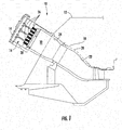
- Fig. 1 provides a simplified cross-section of an exemplary combustor 10, such as may be included in a gas turbine.
- a casing 12 and an end cover 14 may surround the combustor 10 to define a volume 16 inside the combustor 10, a volume that may also be referred to as the head end of the combustor 10.
- a working fluid may pass through flow holes 18 in an impingement sleeve 20 to flow along the outside of a transition piece 22 and a liner 24 to provide convective cooling to the transition piece 22 and liner 24.
- the working fluid When the working fluid reaches the head end or volume 16, the working fluid reverses direction to flow through one or more nozzles 26 radially arranged in an end cap 28.
- the end cap 28 extends radially across at least a portion of the combustor 10 and generally separates the head end or volume 16 from a combustion chamber 30.
- the one or more nozzles 26 extend through the end cap 28 to provide fluid communication through the end cap 28 to the combustion chamber 30 downstream from the end cap 28.
- upstream and downstream refer to the relative location of components in a fluid pathway. For example, component A is upstream from component B if a fluid flows from component A to component B. Conversely, component B is downstream from component A if component B receives a fluid flow from component A.
- the various embodiments of the present invention include means for conditioning flow through the volume 16.
- the function "conditioning flow through the volume” includes improving one or more features of the working fluid flowing through the head end.
- the function "conditioning flow through the volume” may include reducing the size of low flow regions or areas in the head end to reduce the differential pressure of the working fluid across the head end.
- the function "conditioning flow through the volume” may include reducing the acoustic volume of the head end to reduce combustion dynamics produced by the working fluid flowing through the head end.
- the structure for "conditioning flow through the volume” may include one or more modular inserts as shown, for example, in Figs. 2-4 .
- the means for conditioning flow may include one or more annular inserts 40 sized to circumferentially extend around the end cover 14.
- the annular insert 40 may include one or more scalloped features 42 that create a desired pattern on the end cover 14 to optimally reduce the acoustic volume of the head end while not interfering with penetrations through the end cover 14.
- the annular insert 40 may further include one or more angled or concave surfaces 44 to reduce the size of low flow regions and/or reduce the pressure drop of the working fluid across the head end.
- the means for conditioning flow may include one or more arcuate inserts 50, alone or in combination with the annular insert 40, as shown in Figs. 2-4 .
- the arcuate insert 50 may circumferentially extend around the annular insert 40 and/or end cover 14. In this manner, the dimensions of the arcuate insert 50 may be adjusted as necessary to supplement or optimize the conditioning provided by the annular insert 40.
- multiple arcuate inserts 50 may be strategically arranged in low flow regions around the end cover 14 and/or nozzles 26 to reduce the size of the low flow regions and/or reduce the pressure drop across the head end without excessively reducing the acoustic volume of the head end.
- the arcuate inserts 50 may include one or more angled or sloped surfaces 52, as shown in Fig. 2 , concave surfaces 54, as shown in Fig. 3 , and/or convex surfaces 56, as shown in Fig. 4 .
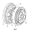
- Figs. 5-7 provide perspective views of various embodiments of the combustor head end with the modular inserts shown in Figs. 2-4 , respectively.
- the annular insert 40 circumferentially extends around the end cover 14, and the scalloped features 42 allow the annular insert 40 to reduce the acoustic volume of the head end while not interfering with penetrations through the end cover 14.
- the annular insert 40 is generally located adjacent to or proximate to the end cover 14 and may be bolted, clamped, or otherwise attached to at least one of the casing 12 and/or the end cover 14 to fixedly hold the annular insert 40 in place.
- the arcuate insert 50 circumferentially extends around the end cover 14 to supplement or optimize the conditioning provided by the annular insert 40.
- the multiple arcuate inserts 50 are strategically arranged in low flow regions around the end cover 14 and/or nozzles 26 to reduce the size of the low flow regions and/or reduce the pressure drop across the head end without excessively reducing the acoustic volume of the head end. In each embodiment shown in Figs.
- the arcuate inserts 50 are adjacent to or proximate to the annular insert 40 and may be bolted, clamped, or otherwise attached to at least one of the casing 12, end cover 14, and/or annular insert 40 to fixedly hold the arcuate inserts 50 in place.
- the arcuate inserts 50 may be installed adjacent to or proximate to the end cover 14 without the use of the annular insert 40.
- the structure for "conditioning flow through the volume” may include one or more modular inserts as shown, for example, in Figs. 8 and 9 .
- the means for conditioning flow may include one or more arcuate inserts 60 configured to fit between one or more nozzles 26 on or adjacent to the end cap 28.
- the arcuate inserts 60 may include concave sides 62 to fit between, conform to, and/or complement the shape of the nozzles 26.
- the arcuate inserts 60 may include a convex surface 64 to assist in distributing working fluid to adjacent nozzles 26.
- the thickness of the arcuate inserts 60 may be adjusted to optimally reduce the acoustic volume of the head end, and the concave sides 62 and convex surface 64 may enhance working fluid flow through into the nozzles 26, reduce the size of low flow regions adjacent to the nozzles 26, and/or reduce the pressure drop of the working fluid across the head end.
- Fig. 10 provides a perspective view of the combustor head end with the modular inserts shown in Figs. 2 and 8 .
- the means for conditioning flow through the volume includes the arcuate insert 50 shown in Fig. 2 , without the annular insert 40, with the arcuate insert 50 adjacent to the end cover 14.
- the means for conditioning flow also includes the arcuate inserts 60 shown in Fig. 8 adjacent to the end cap 28.
- arcuate insert 50 adjacent to the end cover 14 and the arcuate inserts 60 adjacent to the end cap 28 reduces the size of low flow regions in the volume 16 and between adjacent nozzles 26 and/or reduces the pressure drop of the working fluid across the head end to reduce combustion dynamics associated with the working fluid flow through the head end.
- the various embodiments of the present invention shown in Figs. 2-10 may also provide a method for conditioning flow through the combustor 10.
- the method generally includes flowing the working fluid through the volume 16 at least partially defined by the end cover 14, the casing 12, and the end cap 28 and flowing the working fluid across one or more of the modular inserts shown in Figs. 2-4 .
- the method may include flowing the working fluid across the annular insert 40 adjacent to the end cover 14, as shown specifically in Figs. 5-7 .
- the method may include flowing the working fluid across the arcuate inserts 50 adjacent to the annular insert 40, as shown specifically in Figs. 5-7 , or adjacent to the end cover 14, as shown specifically in Fig. 10 .
- the method may include flowing the working fluid across the arcuate inserts 60 adjacent to the end cap 28, as shown specifically in Figs. 9 and 10 .
- Figs. 2-10 provide one or more technical advantages to enhance flow through the combustor 10.
- the modular nature of the various inserts shown in Figs. 2-4 and 8 allow various combinations of the modular inserts to optimally adjust one or more of the size of low flow regions, the differential pressure of the working fluid across the head end, and/or the acoustic volume of the head end to reduce combustion dynamics produced by the working fluid flowing through the head end.
- the reduction or removal of destructive dynamics may enhance the thermodynamic efficiency of the combustor 10, protect the combustor 10 from catastrophic damage, and/or reduce undesirable emissions over a wide range of combustor 10 operating levels.
Landscapes
- Engineering & Computer Science (AREA)
- Chemical & Material Sciences (AREA)
- Combustion & Propulsion (AREA)
- Mechanical Engineering (AREA)
- General Engineering & Computer Science (AREA)
- Gas Burners (AREA)
Applications Claiming Priority (1)
| Application Number | Priority Date | Filing Date | Title |
|---|---|---|---|
| US13/237,064 US20130067923A1 (en) | 2011-09-20 | 2011-09-20 | Combustor and method for conditioning flow through a combustor |
Publications (1)
| Publication Number | Publication Date |
|---|---|
| EP2573465A2 true EP2573465A2 (de) | 2013-03-27 |
Family
ID=46888310
Family Applications (1)
| Application Number | Title | Priority Date | Filing Date |
|---|---|---|---|
| EP12183805A Withdrawn EP2573465A2 (de) | 2011-09-20 | 2012-09-11 | Brennkammer und Verfahren zur Konditionierung der Strömung durch eine Brennkammer |
Country Status (3)
| Country | Link |
|---|---|
| US (1) | US20130067923A1 (de) |
| EP (1) | EP2573465A2 (de) |
| CN (1) | CN103017201A (de) |
Families Citing this family (2)
| Publication number | Priority date | Publication date | Assignee | Title |
|---|---|---|---|---|
| US9670846B2 (en) | 2013-07-29 | 2017-06-06 | General Electric Company | Enhanced mixing tube elements |
| US9500367B2 (en) | 2013-11-11 | 2016-11-22 | General Electric Company | Combustion casing manifold for high pressure air delivery to a fuel nozzle pilot system |
Family Cites Families (4)
| Publication number | Priority date | Publication date | Assignee | Title |
|---|---|---|---|---|
| DE19627760C2 (de) * | 1996-07-10 | 2001-05-03 | Mtu Aero Engines Gmbh | Brenner mit Zerstäuberdüse |
| EP1096201A1 (de) * | 1999-10-29 | 2001-05-02 | Siemens Aktiengesellschaft | Brenner |
| DE10219354A1 (de) * | 2002-04-30 | 2003-11-13 | Rolls Royce Deutschland | Gasturbinenbrennkammer mit gezielter Kraftstoffeinbringung zur Verbesserung der Homogenität des Kraftstoff-Luft-Gemisches |
| GB2444737B (en) * | 2006-12-13 | 2009-03-04 | Siemens Ag | Improvements in or relating to burners for a gas turbine engine |
-
2011
- 2011-09-20 US US13/237,064 patent/US20130067923A1/en not_active Abandoned
-
2012
- 2012-09-11 EP EP12183805A patent/EP2573465A2/de not_active Withdrawn
- 2012-09-20 CN CN2012103502829A patent/CN103017201A/zh active Pending
Non-Patent Citations (1)
| Title |
|---|
| None |
Also Published As
| Publication number | Publication date |
|---|---|
| US20130067923A1 (en) | 2013-03-21 |
| CN103017201A (zh) | 2013-04-03 |
Similar Documents
| Publication | Publication Date | Title |
|---|---|---|
| EP2629017B1 (de) | Brennkammer | |
| US8904798B2 (en) | Combustor | |
| EP2559946B1 (de) | System und Verfahren zur Verringerung der Verbrennungsdynamik in einem Brennkammer | |
| EP2578944B1 (de) | Brennkammer und Verfahren zur Versorgung einer Brennkammer mit Brennstoff | |
| EP2584266B1 (de) | Brennkammer und Verfahren zur Konditionierung der Strömung durch eine Brennkammer | |
| US9353950B2 (en) | System for reducing combustion dynamics and NOx in a combustor | |
| EP2573469B1 (de) | Brennkammer zur Versorgung einer Brennkammer mit Brennstoff | |
| EP2634488B1 (de) | System und Verfahren zur Verringerung der Verbrennungsdynamik in einer Turbomaschine | |
| EP2578939B1 (de) | Brennkammer und Verfahren zur Strömungsversorgung einer Brennkammer | |
| EP2634487A2 (de) | System und Verfahren zur Verringerung der Verbrennungsdynamik in einer Turbomaschine | |
| US9249734B2 (en) | Combustor | |
| EP3315866B1 (de) | Brennkammeranordnung mit montierter hilfskomponente | |
| EP3220051A1 (de) | Gebündelte rohrbrennstoffdüse mit vibrationsdämpfung | |
| EP2679775A1 (de) | Überleitkanal für eine Gasturbine | |
| EP3220053A1 (de) | Halterung für axial gestuften kraftstoffeinspritzer und montageverfahren | |
| EP3220049B1 (de) | Gasturbinenbrennkammer mit wandkühlleitblechen | |
| EP2573465A2 (de) | Brennkammer und Verfahren zur Konditionierung der Strömung durch eine Brennkammer | |
| EP2532964A2 (de) | System zur Konditionierung des Durchflusses durch eine Brennkammer | |
| EP3220048A1 (de) | Brennkammerwandkühlung | |
| EP2532957A2 (de) | System zur Konditionierung des Durchflusses durch eine Düse |
Legal Events
| Date | Code | Title | Description |
|---|---|---|---|
| PUAI | Public reference made under article 153(3) epc to a published international application that has entered the european phase |
Free format text: ORIGINAL CODE: 0009012 |
|
| AK | Designated contracting states |
Kind code of ref document: A2 Designated state(s): AL AT BE BG CH CY CZ DE DK EE ES FI FR GB GR HR HU IE IS IT LI LT LU LV MC MK MT NL NO PL PT RO RS SE SI SK SM TR |
|
| AX | Request for extension of the european patent |
Extension state: BA ME |
|
| STAA | Information on the status of an ep patent application or granted ep patent |
Free format text: STATUS: THE APPLICATION IS DEEMED TO BE WITHDRAWN |
|
| 18D | Application deemed to be withdrawn |
Effective date: 20160401 |