EP2573545B1 - Procédé d'inspection de filière - Google Patents
Procédé d'inspection de filière Download PDFInfo
- Publication number
- EP2573545B1 EP2573545B1 EP11783559.5A EP11783559A EP2573545B1 EP 2573545 B1 EP2573545 B1 EP 2573545B1 EP 11783559 A EP11783559 A EP 11783559A EP 2573545 B1 EP2573545 B1 EP 2573545B1
- Authority
- EP
- European Patent Office
- Prior art keywords
- porous alumina
- parameter
- alumina layer
- color
- mold
- Prior art date
- Legal status (The legal status is an assumption and is not a legal conclusion. Google has not performed a legal analysis and makes no representation as to the accuracy of the status listed.)
- Active
Links
Images


Classifications
-
- G—PHYSICS
- G01—MEASURING; TESTING
- G01N—INVESTIGATING OR ANALYSING MATERIALS BY DETERMINING THEIR CHEMICAL OR PHYSICAL PROPERTIES
- G01N21/00—Investigating or analysing materials by the use of optical means, i.e. using sub-millimetre waves, infrared, visible or ultraviolet light
- G01N21/17—Systems in which incident light is modified in accordance with the properties of the material investigated
- G01N21/25—Colour; Spectral properties, i.e. comparison of effect of material on the light at two or more different wavelengths or wavelength bands
- G01N21/29—Colour; Spectral properties, i.e. comparison of effect of material on the light at two or more different wavelengths or wavelength bands using visual detection
-
- G—PHYSICS
- G01—MEASURING; TESTING
- G01J—MEASUREMENT OF INTENSITY, VELOCITY, SPECTRAL CONTENT, POLARISATION, PHASE OR PULSE CHARACTERISTICS OF INFRARED, VISIBLE OR ULTRAVIOLET LIGHT; COLORIMETRY; RADIATION PYROMETRY
- G01J3/00—Spectrometry; Spectrophotometry; Monochromators; Measuring colours
- G01J3/46—Measurement of colour; Colour measuring devices, e.g. colorimeters
-
- G—PHYSICS
- G01—MEASURING; TESTING
- G01B—MEASURING LENGTH, THICKNESS OR SIMILAR LINEAR DIMENSIONS; MEASURING ANGLES; MEASURING AREAS; MEASURING IRREGULARITIES OF SURFACES OR CONTOURS
- G01B11/00—Measuring arrangements characterised by the use of optical techniques
- G01B11/02—Measuring arrangements characterised by the use of optical techniques for measuring length, width or thickness
- G01B11/06—Measuring arrangements characterised by the use of optical techniques for measuring length, width or thickness for measuring thickness ; e.g. of sheet material
- G01B11/0616—Measuring arrangements characterised by the use of optical techniques for measuring length, width or thickness for measuring thickness ; e.g. of sheet material of coating
- G01B11/0625—Measuring arrangements characterised by the use of optical techniques for measuring length, width or thickness for measuring thickness ; e.g. of sheet material of coating with measurement of absorption or reflection
- G01B11/0633—Measuring arrangements characterised by the use of optical techniques for measuring length, width or thickness for measuring thickness ; e.g. of sheet material of coating with measurement of absorption or reflection using one or more discrete wavelengths
-
- G—PHYSICS
- G01—MEASURING; TESTING
- G01B—MEASURING LENGTH, THICKNESS OR SIMILAR LINEAR DIMENSIONS; MEASURING ANGLES; MEASURING AREAS; MEASURING IRREGULARITIES OF SURFACES OR CONTOURS
- G01B21/00—Measuring arrangements or details thereof, where the measuring technique is not covered by the other groups of this subclass, unspecified or not relevant
- G01B21/02—Measuring arrangements or details thereof, where the measuring technique is not covered by the other groups of this subclass, unspecified or not relevant for measuring length, width, or thickness
- G01B21/08—Measuring arrangements or details thereof, where the measuring technique is not covered by the other groups of this subclass, unspecified or not relevant for measuring length, width, or thickness for measuring thickness
-
- G—PHYSICS
- G01—MEASURING; TESTING
- G01J—MEASUREMENT OF INTENSITY, VELOCITY, SPECTRAL CONTENT, POLARISATION, PHASE OR PULSE CHARACTERISTICS OF INFRARED, VISIBLE OR ULTRAVIOLET LIGHT; COLORIMETRY; RADIATION PYROMETRY
- G01J3/00—Spectrometry; Spectrophotometry; Monochromators; Measuring colours
- G01J3/46—Measurement of colour; Colour measuring devices, e.g. colorimeters
- G01J3/465—Measurement of colour; Colour measuring devices, e.g. colorimeters taking into account the colour perception of the eye; using tristimulus detection
-
- G—PHYSICS
- G01—MEASURING; TESTING
- G01N—INVESTIGATING OR ANALYSING MATERIALS BY DETERMINING THEIR CHEMICAL OR PHYSICAL PROPERTIES
- G01N21/00—Investigating or analysing materials by the use of optical means, i.e. using sub-millimetre waves, infrared, visible or ultraviolet light
- G01N21/84—Systems specially adapted for particular applications
- G01N21/88—Investigating the presence of flaws or contamination
- G01N21/8803—Visual inspection
-
- G—PHYSICS
- G01—MEASURING; TESTING
- G01N—INVESTIGATING OR ANALYSING MATERIALS BY DETERMINING THEIR CHEMICAL OR PHYSICAL PROPERTIES
- G01N21/00—Investigating or analysing materials by the use of optical means, i.e. using sub-millimetre waves, infrared, visible or ultraviolet light
- G01N21/84—Systems specially adapted for particular applications
- G01N21/88—Investigating the presence of flaws or contamination
- G01N21/95—Investigating the presence of flaws or contamination characterised by the material or shape of the object to be examined
- G01N21/956—Inspecting patterns on the surface of objects
-
- G—PHYSICS
- G01—MEASURING; TESTING
- G01N—INVESTIGATING OR ANALYSING MATERIALS BY DETERMINING THEIR CHEMICAL OR PHYSICAL PROPERTIES
- G01N2201/00—Features of devices classified in G01N21/00
- G01N2201/06—Illumination; Optics
- G01N2201/063—Illuminating optical parts
- G01N2201/0634—Diffuse illumination
Definitions
- the present invention relates to a mold inspection method.
- the "mold” includes molds that are for use in various processing methods (stamping and casting), and is sometimes referred to as a stamper.
- the "mold” can also be used for printing (including nanoimprinting).
- Display devices for use in TVs, cell phones, etc., and optical elements, such as camera lenses, etc. usually adopt an antireflection technique in order to reduce the surface reflection and increase the amount of light transmitted therethrough. This is because, when light is transmitted through the interface between media of different refractive indices, e.g., when light is incident on the interface between air and glass, the amount of transmitted light decreases due to, for example, Fresnel reflection, thus deteriorating the visibility.
- the two-dimensional size of a raised portion of an uneven pattern which performs an antireflection function is not less than 10 nm and less than 500 nm.
- This method utilizes the principles of a so-called moth-eye structure.
- the refractive index for light that is incident on the substrate is continuously changed along the depth direction of the recessed portions or raised portions, from the refractive index of a medium on which the light is incident to the refractive index of the substrate, whereby reflection of a wavelength band that is subject to antireflection is prevented.
- the moth-eye structure is advantageous in that it is capable of performing an antireflection function with small incident angle dependence over a wide wavelength band, as well as that it is applicable to a number of materials, and that an uneven pattern can be directly formed in a substrate. As such, a high-performance antireflection film (or antireflection surface) can be provided at a low cost.
- Patent Documents 2 to 4 As the method of forming a moth-eye structure, using an anodized porous alumina layer which is obtained by means of anodization of aluminum has been receiving attention (Patent Documents 2 to 4).
- anodized porous alumina layer which is obtained by means of anodization of aluminum is briefly described.
- a method of forming a porous structure by means of anodization has been receiving attention as a simple method for making nanometer-scale micropores (very small recessed portions) in the shape of a circular column in a regular arrangement.
- An aluminum base is immersed in an acidic electrolytic solution of sulfuric acid, oxalic acid, phosphoric acid, or the like, or an alkaline electrolytic solution, and this is used as an anode in application of a voltage, which causes oxidation and dissolution.
- the oxidation and the dissolution concurrently advance over a surface of the aluminum base to form an oxide film which has micropores over its surface.
- micropores which are in the shape of a circular column, are oriented vertical to the oxide film and exhibit a self-organized regularity under certain conditions (voltage, electrolyte type, temperature, etc.).
- this anodized porous alumina layer is expected to be applied to a wide variety of functional materials.
- a porous alumina layer formed under specific conditions includes cells in the shape of a generally regular hexagon which are in a closest packed two-dimensional arrangement when seen in a direction perpendicular to the film surface. Each of the cells has a micropore at its center. The arrangement of the micropores is periodic. The cells are formed as a result of local dissolution and growth of a coating. The dissolution and growth of the coating concurrently advance at the bottom of the micropores which is referred to as a barrier layer. As known, the size of the cells, i.e., the interval between adjacent micropores (the distance between the centers), is approximately twice the thickness of the barrier layer, and is approximately proportional to the voltage that is applied during the anodization.
- micropores depends on the type, concentration, temperature, etc., of the electrolytic solution but is, usually, about 1/3 of the size of the cells (the length of the longest diagonal of the cell when seen in a direction vertical to the film surface).
- Such micropores of the porous alumina may constitute an arrangement which has a high regularity (periodicity) under specific conditions, an arrangement with a regularity degraded to some extent depending on the conditions, or an irregular (non-periodic) arrangement.
- Patent Document 2 discloses a method of producing an antireflection film (antireflection surface) with the use of a stamper which has an anodized porous alumina film over its surface.
- Patent Document 3 discloses the technique of forming tapered recesses with continuously changing pore diameters by repeating anodization of aluminum and a pore diameter increasing process.
- Patent Document 4 discloses, in Patent Document 4, the technique of forming an antireflection film with the use of an alumina layer in which very small recessed portions have stepped lateral surfaces.
- the antireflection film (antireflection surface) can be provided with an antiglare function.
- the two-dimensional size of a raised portion of the uneven structure which is capable of performing the antiglare function is not less than 1 ⁇ m and less than 100 ⁇ m.
- Utilizing an anodized porous aluminum film can facilitate the manufacture of a mold which is used for formation of a moth-eye structure over a surface (hereinafter, "moth-eye mold”).
- a mold which is used for formation of a moth-eye structure over a surface
- FIG. 2 and 4 when the surface of the anodized aluminum film as formed is used as a mold without any modification, a large effect of reducing the manufacturing cost is achieved.
- the structure of the surface of a moth-eye mold which is capable of forming a moth-eye structure is herein referred to as "inverted moth-eye structure".
- a known antireflection film production method with the use of a moth-eye mold uses a photocurable resin. Firstly, a photocurable resin is applied over a substrate. Then, an uneven surface of a moth-eye mold which has undergone a mold release treatment is pressed against the photocurable resin in vacuum. Thereafter, the uneven structure is filled with the photocurable resin. Then, the photocurable resin in the uneven structure is irradiated with ultraviolet light so that the photocurable resin is cured. Thereafter, the moth-eye mold is separated from the substrate, whereby a cured layer of the photocurable resin to which the uneven structure of the moth-eye mold has been transferred is formed over the surface of the substrate.
- the method of producing an antireflection film with the use of the photocurable resin is disclosed in, for example, Patent Document 4.
- the uneven structure at the surface of a moth-eye mold is a minute structure of less than 1 ⁇ m.
- a SEM scanning electron microscope
- D int the distance between adjacent recessed portions
- D p the two-dimensional size of recessed portions
- t p the thickness of a porous alumina layer
- the present invention was conceived for the purpose of solving the above problems.
- One of the major objects of the present invention is to provide a method for nondestructively and readily inspecting, in the step of forming a surface which has a minute uneven structure whose D p is less than 1 ⁇ m, such as a surface of a moth-eye mold, whether or not the minute uneven structure at the surface is within a predetermined range.
- a mold inspection method of the present invention is a method comprising the steps of: (a) providing, based on a relationship between first parameter values indicative of thicknesses of porous alumina layers and color parameter values indicative of colors of light reflected from porous alumina layers, a first color information which represents a tolerance range of the first parameter for porous alumina layers having an uneven structure with structure parameters within the tolerance range; (b) providing the mold which is an inspection subject, the mold having a porous alumina layer over its surface; (c) obtaining a color parameter which is indicative of a color of reflected light from the porous alumina layer of the inspection subject mold; and (d) determining a suitability of the first parameter of the inspection subject mold based on the obtained color parameter and the first color information.
- the color parameter includes X or Y of tristimulus values X, Y and Z.
- step (a) includes expressing the relationship of the first parameter and X or Y as an approximation formula.
- step (c) includes measuring a spectral reflectance of the porous alumina layer of the inspection subject mold.
- step (c) includes obtaining the color parameter from each of a plurality of different positions over a surface of the porous alumina layer
- step (d) includes determining a suitability of the first parameter of the inspection subject mold based on the color parameter obtained from each of the plurality of different positions and the first color information.
- the mold inspection method further includes the step of: (e) determining a suitability of the first parameter of the inspection subject mold based on a relationship between a position over a surface of the porous alumina layer and the first parameter.
- the mold inspection method further includes the steps of: (f) providing, based on a relationship between a second parameter that is indicative of an occupancy of the plurality of minute recessed portions of the porous alumina layer and a color parameter that is indicative of a color of reflected light from the porous alumina layer, second color information which represents a tolerance of the second parameter of a porous alumina layer which has an uneven structure that is within a tolerance; and (g) determining a validity of the second parameter of the inspection subject mold based on the obtained color parameter and the second color information.
- step (a) and step (d) may be replaced by step (f) and step (g).
- the second color information provided in step (f) includes X or Y of the tristimulus values X, Y and Z
- the color parameter obtained in step (c) includes X or Y of the tristimulus values X, Y and Z.
- Step (f) includes the step of expressing the relationship between the second parameter and X or Y as an approximation formula.
- the present invention provides a method for nondestructively and readily inspecting whether or not a minute uneven structure whose two-dimensional size is less than 1 ⁇ m, such as a surface of a moth-eye mold, is within a predetermined range.
- a mold inspection method of an embodiment of the present invention is described with reference to the drawings.
- a method for inspecting a moth-eye mold which has a porous alumina layer for production of an antireflection film is exemplified, but the present invention is not limited to this example.
- the present invention is also applicable to inspection of a surface of the porous alumina layer which has a minute uneven structure whose two-dimensional size viewed in a direction normal to the surface (D p ) is less than 1 ⁇ m.
- FIG. 1 is a cross-sectional SEM image of the porous alumina layer that is used in production of an antireflection film. Further, a schematic structure of this porous alumina layer 6 is shown in FIGS. 2(a) and 2(b) .
- the porous alumina layer 6 has a large number of minute recessed portions 8.
- the porous alumina layer 6 is obtained by performing anodization and etching on a surface of an aluminum base (or aluminum film) 4 as will be described later.
- the cross-sectional shape of the minute recessed portions of the porous alumina layer that is used in production of an antireflection film is generally conical. It is preferred that the two-dimensional size of the minute recessed portions 8 (opening diameter: D p ) is not less than 10 nm and less than 500 nm, and the depth of the minute recessed portions 8 (D depth ) is generally not less than 10 nm and less than 1000 nm (1 ⁇ m). It is also preferred that the bottom portion of the minute recessed portions 8 is tapered (with the deepest part of the bottom portion being pointed). Further, it is preferred that the minute recessed portions 8 are in a closely packed arrangement.
- the shape of the minute recessed portions 8 of the porous alumina layer 6 when viewed in a direction normal to the porous alumina layer 6 is a circle
- adjacent circles overlap each other, and a saddle portion is formed between adjacent ones of the minute recessed portions 8 .
- the two-dimensional size of the minute recessed portions 8 , D p is equal to the average adjoining distance D int .
- an aluminum film (about 1 ⁇ m thick) deposited on a glass substrate was anodized with a forming voltage of 80 V for 60 seconds using a 0.1 M oxalic acid aqueous solution (18°C) as the electrolytic solution and thereafter immersed in a 2 mass% phosphoric acid aqueous solution (30°C) as the etching solution for 90 minutes, whereby an anodized layer formed in the previous anodization step was removed.
- the minute uneven structure of the first-formed porous alumina layer is unstable in many cases, and therefore, it is preferred, for improvement of reproducibility, that the first-formed porous alumina layer is removed, and thereafter, another porous alumina layer is formed.
- the anodization step (5 cycles) and the etching step (4 cycles) were alternately repeated using the aforementioned electrolytic solution (at the same temperature) and the aforementioned etching solution (at the same temperature).
- the duration of one cycle of the anodization step was 25 seconds, and the duration of one cycle of the etching step was 19 minutes (these conditions were the same as those of Sample C which will be described below).
- the anodization duration is increased, the depth of the minute recessed portions increases.
- the etching duration is increased, the opening diameter of the minute recessed portions increases.
- the structure of the minute recessed portions can be controlled by alternately performing the anodization and the etching respectively for appropriate durations.
- the minute uneven structure at the surface of the porous alumina layer varies mainly due to a variation of the duration of the anodization step and a variation of the duration of the etching step, and as a result, defective products can be manufactured.
- a variation of the temperature of the electrolytic solution and a variation of the temperature of etching solution can affect the minute uneven structure.
- the minute uneven structure is attributed to a variation in degree of the anodization and a variation in degree of the etching.
- the thickness of the porous alumina layer, t p increases.
- the depth of the minute recessed portions, D depth increases according to the increase of the thickness of the porous alumina layer t p .
- the thickness of the porous alumina layer, t p can be recognized as a parameter that is indicative of the depth of the minute recessed portions, D depth .
- the correlation between t p and D depth is high as compared with a case where the process is finished with the etching step.
- samples A to G the duration of the anodization step is different, but the duration of the etching step is equal.
- the samples A to G can be recognized as having generally similar cross-sectional shapes of the minute recessed portions, while only the thickness of the porous alumina layer, t p , and the depth of the minute recessed portions, D depth , are different.
- D int is generally equal among samples A to G.
- the thickness t p of the porous alumina layer is greater than the depth D depth by the thickness t b of the barrier layer.
- D int is generally equal among samples J to M.
- the porous alumina layers of samples A to G of Table 1 and samples J to M shown in Table 2 appear to have different colors. Specifically, reflected light appears tinted. The color of reflected light was evaluated as shown in FIG. 4 . Specifically, a sample 1 with a porous alumina layer over its surface was placed generally horizontally on an examination table 20. Light emitted from a white light source (e.g., fluorescent lamp) 22 was reflected by a diffuse reflection plate 24 so as to strike the surface of the porous alumina layer, and reflection from the surface with reflection angle ⁇ of approximately 90° was evaluated by an observer 32 by means of visual observation. The results of the evaluation are shown in Tables 1 and 2.
- a white light source e.g., fluorescent lamp
- the color of the reflected light sensitively varies depending on thickness t p (depth D depth ) and the shape (width) of the recessed portions.
- Various samples were prepared according to the same method as that described above, and the relationship between thickness t p and the shape (width) of the recessed portions and the color of the reflected light was mapped in FIG. 5 .
- the recessed portion occupancy (%) is discussed, which serves as a parameter that quantitatively expresses the shape (width) of the recessed portions.
- the width of the recessed portions also varies. That is, the volume of the recessed portions varies.
- the cross section of this cylinder (including the diameter) has a rectangular shape as shown in FIG. 5 .
- the area ratio of the recessed portions in the cross section of the rectangle also increases.
- the area ratio of the recessed portions to the area of the rectangle is represented as the occupancy of the recessed portions.
- the occupancy of the recessed portions may be represented by the volume ratio of the recessed portions to the cylinder, instead of the area ratio of the recessed portions.
- the duration of one cycle of the etching step is long, e.g., from a few minutes to 20 minutes, whereas the duration of one cycle of the anodization step is several tens of seconds. It is therefore inferred that the variation of the shape (width) of the recessed portions which is caused by the etching step is small, and approximation of the recessed portion occupancy by the area ratio would not cause any problem.
- FIG. 5 illustrates the relationship between thickness t p and the recessed portion occupancy and the color of reflected light, where a porous alumina layer which is configured such that thickness t p is 400 nm and the recessed portion occupancy is 50% is at the center. Thickness t p and the recessed portion occupancy were determined from the cross-sectional SEM images, and the color of reflected light was evaluated according to the method that has previously been described with reference to FIG. 4 .
- the porous alumina layer that is present at the center appears pink.
- thickness t p increases, the color changes to orange and then yellow.
- thickness t p decreases, the color changes to pale purple and then purple.
- the recessed portion occupancy increases, the color changes to orange and then yellow.
- the color changes to pale purple and then purple.
- the reflected light appears pink when the recessed portion occupancy is 45%, 50%, and 55%, respectively.
- the values of thickness t p and the recessed portion occupancy are within the regions encircled by broken lines in FIG. 5 , the reflected light appears in the same color.
- a resultant product will be regarded as a good product.
- This criterion was determined based on the antireflection property of an antireflection film which was produced using a moth-eye mold that includes a porous alumina layer. This criterion for determination of a good product is merely an example.
- the reference values (thresholds) of thickness t p and the recessed portion occupancy are appropriately determined.
- a method for nondestructively and readily inspecting whether or not the minute uneven structure at the surface of the porous alumina layer is within a predetermined range specifically, in the above example, whether or not thickness t p is 400 nm ⁇ 40 nm and whether or not the recessed portion occupancy (here, the area ratio) is in the range of not less than 45% and not more than 55%, was examined.
- 400 nm was the center value, but the center value is not limited to this value.
- the color varies within the range of ⁇ 40 nm, and there is no probability that the same color repeatedly occurs in this range (e.g., the same color occurs at +40 nm and -40 nm).
- the method that is exemplified herein is applicable without making any modification.
- a method for nondestructively and readily inspecting whether or not the thickness of the porous alumina layer, t p , is within a predetermined range was examined.
- a predetermined range e.g., within the range of 400 nm ⁇ 40 nm
- the duration of one cycle of the etching step is long, e.g., from several minutes to about 20 minutes, whereas the duration of one cycle of the anodization step is several tens of seconds. Therefore, the variation of the shape (width) of the recessed portions which is caused in the etching step is small.
- a factor which actually matters in a mass-production process is management of the thickness of the porous alumina layer, t p , (which is associated with the depth of the minute recessed portions).
- a mold inspection method of an embodiment of the present invention includes the steps of: (a) providing, based on a relationship between first parameter values indicative of thicknesses of porous alumina layers and color parameter values indicative of colors of light reflected from porous alumina layers, a first color information which represents a tolerance range of the first parameter for porous alumina layers having an uneven structure with structure parameters within the tolerance range; (b) providing the mold which is an inspection subject, the mold having a porous alumina layer over its surface; (c) obtaining a color parameter which is indicative of the color of reflected light from the porous alumina layer of the inspection subject mold; and (d) determining the suitability of the first parameter of the inspection subject mold based on the obtained color parameter and the first color information.
- the first color information is provided which represents the tolerance of the first parameter of the porous alumina layer that has an uneven structure that is within a tolerance based on the relationship between the first parameter and the color parameter which has been prepared beforehand.
- the first parameter may be the thickness of the porous alumina layer, t p , which is correctly determined from a cross-sectional SEM image, for example, or the depth of the recessed portions, D depth , which is directly associated with thickness t p .
- the color parameter represents the color of reflected light from the porous alumina layer.
- the color parameter is, for example, tristimulus values (X, Y and Z).
- the porous alumina layer that has an uneven structure that is within a tolerance refers to a porous alumina layer in which a parameter other than the first parameter (here, the shape (width) of the recessed portions which is represented by the recessed portion occupancy) is within a tolerance.
- a parameter other than the first parameter here, the shape (width) of the recessed portions which is represented by the recessed portion occupancy
- it includes porous alumina layers which are represented by five boxes aligned along the vertical line of the 50% recessed portion occupancy in FIG. 5 .
- the first color information which represents the tolerance of the first parameter of these porous alumina layers refers to, in the example shown in FIG. 5 , color information which represents that thickness t p is not less than 375 nm and not more than 425 nm.
- the information that "the color of reflected light is any of orange, pink, and pale purple, or any color between these colors” corresponds to this first color information.
- the first color information is computer-processable information and is determined based on the above-described color parameter. For example, it may be the lower limit value and the upper limit value which are represented by tristimulus values (X, Y and Z) (also referred to as “thresholds" or "boundary values").
- step (c) which represents the color of reflected light from the porous alumina layer of the inspection subject mold prepared in step (b).
- This color parameter is to be compared with the first color information and is equivalent to the color parameter in step (a).
- the color parameter is, for example, tristimulus values.
- step (d) the color parameter obtained in step (c) and the first color information which is represented by the color parameter are compared in order to determine whether or not the first parameter of the inspection subject mold is within the tolerance.
- the condition that it can be determined using the color parameter whether or not the first parameter that is indicative of thickness t p is within a desired range means that the thickness of the porous alumina layer, t p , can be indirectly measured using the color parameter. Determining thickness t p with the use of the color parameter provides various advantages as described below.
- a commonly-known method for measuring the thickness of a thin film is a measuring method in which an ellipsometer is used. Using an ellipsometer enables to accurately determine the thickness of a single layer film whose complex refractive index is known.
- the porous alumina layer includes a layer which is constituted of the minute recessed portions and a barrier layer.
- the complex refractive index of the porous layer is not constant but varies along the thickness direction according to the proportion of alumina portions and vacancy portions. Further, the bottom of the barrier layer is not flat, and therefore, there is a layer in which alumina and an aluminum layer are intermingled with each other.
- the color parameter can be determined from the spectral reflectance, for example. Measurement of the spectral reflectance (reflection spectrum) only requires setting of the optical axis on the light receiving side, and the accuracy in setting of the optical axis may not be high.
- a spectral color measuring system COMES registered trademark manufactured by NIRECO CORPORATION enables to determine tristimulus values X, Y and Z from the spectral reflectance.
- the color parameter is not limited to the tristimulus values but may be L*, a*, b*, for example.
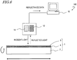
- the mold inspection method of an embodiment of the present invention may be realized by using an inspection system 100 shown in FIG. 6 .
- the inspection system 100 shown in FIG. 6 includes a white light source 12 , a spectroscope 14 , and a computer 16 which is configured to control the white light source 12 and the spectroscope 14 and to process data obtained from the spectroscope 14.
- the computer 16 includes an operational processing unit and a memory unit.
- the memory unit stores data obtained from the spectroscope 14 and data of the first color information, and the like, as well as software for various operational processing.
- the inspection system 100 quantitatively determines the color of reflected light from the porous alumina layer as follows. As shown in FIG. 6 , the white light source 12 and the spectroscope 14 of the inspection system 100 are placed at predetermined positions relative to an inspection subject mold 1.
- the inspection subject mold 1 includes, for example, a support 2 , an aluminum film 8 deposited on the support 2 , and a porous alumina layer 6 which is formed by anodizing a surface of the aluminum film.
- Light is emitted from a white light source 12 (e.g., white LED, a xenon lamp) of the inspection system 100 toward the surface of the porous alumina layer 6 of the mold 1.
- a white light source 12 e.g., white LED, a xenon lamp
- the measured wavelength range is, for example, from 400 nm to 700 nm.
- the wavelength resolution is 1.5 nm.
- the measurement duration is 155 msec at each point.
- a spectral reflectance characteristic such as shown in FIG. 7 is obtained.
- the vertical reflectance (Rv) was measured.
- the reflection spectrum illustrated herein is a measurement result for a porous alumina layer which was formed over a surface of a cylindrical aluminum base (diameter: 150 mm, length: 600 mm) such that the thickness of the porous alumina layer, t p , is 520 nm as in previously-described sample F.
- 50 mm is the length measured from the upper end of the cylinder (e.g., the upper end of the cylinder when immersed in a treatment solution in the anodization and the etching).
- 270° is the angle for specifying the coordinates over the perimeter of the cylinder, which refers to the angle that is formed by a line extending between the measuring point and the center of the cylinder with a reference line (a line extending between the reference point and the center of the cylinder).
- the reference point may be any point and may be appropriately determined according to the setting of the apparatus.
- the spectral reflectance characteristic is stored together with the information about the measuring point in the computer 16 .
- PV method peak-valley method
- the operation of determining the tristimulus values from the spectral reflectance characteristic is carried out by the computer 16.
- the result of the operation is stored in the memory unit and, meanwhile, when necessary, output to a display, printer, or the like.
- the operation of determining the color parameter, such as the tristimulus values, from the spectral characteristics and the operation for conversion between color parameters are well known, and therefore, the descriptions thereof are omitted herein.
- the first color information that serves as a criterion for determination of good products may be determined, for example, as described below.
- film thickness t p is the target of management.
- a good product sample of which film thickness t p is within the tolerance a film thickness lower limit sample of which film thickness t p is just below the lower limit of the tolerance, and a film thickness upper limit sample of which film thickness t p is just above the upper limit of the tolerance are prepared.
- X, Y and Z are determined according to the above-described method.
- Each of the samples used herein satisfies a condition that the shape of the minute recessed portions (the recessed portion occupancy) is within a tolerance.
- the correlation function between film thickness t p and each of X, Y and Z is determined.
- the first color information includes the values of Xa, Ya, and Za of the film thickness lower limit sample and the values of Xb, Yb, and Zb of the film thickness upper limit sample.
- X and Y are generally proportional to film thickness t p and are therefore associated with film thickness t p at higher accuracy than in the case where Z is used.
- X and/or Y as the color parameter is preferred. It is not necessary to determine every one of the relationships between X, Y and Z and film thickness t p .
- X, Y and Z are determined according to the above-described method and compared with the first color information. Specifically, the determined X, Y and Z are compared with Xa, Ya, Za, Xb, Yb, and Zb to determine whether or not they lie between these values. If they lie within the range of these values, it is determined to be suitable. If they lie outside the range, it is determined to be not suitable. Further, thickness t p can be determined by substituting corresponding X, Y or Z in the quadratic polynomial. As a matter of course, the suitability may be determined based on t p .
- X, Y and Z are obtained from each of a plurality of different positions over the surface of the porous alumina layer, and X, Y and Z obtained from each of the plurality of positions are compared with Xa, Ya, Za, Xb, Yb, and Zb to determine whether or not they lie between these values.
- the mold 1 may be moved relative to the white light source 12 and the spectroscope 14 as illustrated by a two-way arrow in FIG. 6 .
- the uneven structure of a large-surface porous alumina layer has non-uniformity.
- the recessed portions are deeper (thickness t p is greater) at a position which is closer to the edge of the mold. This is because the anodization advances more readily at a position which is closer to the edge.
- the suitability of the first parameter may be determined. For example, the measurement results at two different positions are compared. If they satisfy the above-described relationship, it is determined to be suitable. If they do not satisfy the above-described relationship, it is determined to be not suitable. In the case where there are a large number of measuring points over a large-surface porous alumina layer, the general tendency of the distribution of the largeness of the value of X, Y or Z is converted into a numerical expression for determination of the suitability.
- the suitability of the occupancy of the recessed portions may be determined as in the above-described method that is for determining the suitability of the film thickness (first parameter).
- the step of providing the second color information which represents the tolerance of the second parameter of the porous alumina layer which has the uneven structure that is within the tolerance based on the relationship between the second parameter that represents the occupancy of a plurality of minute recessed portions of the porous alumina layer and the color parameter that represents the color of reflected light from the porous alumina layer and the step of determining the validity of the second parameter of the inspection subject mold based on the obtained color parameter and the second color information are further performed.
- the step of providing the second color information includes, as in the above-described method, providing a good product sample of which the recessed portion occupancy is within the tolerance, a recessed portion occupancy lower limit sample of which the recessed portion occupancy is just below the lower limit of the tolerance, and a recessed portion occupancy upper limit sample of which the recessed portion occupancy is just above the upper limit of the tolerance, and determining X, Y and Z for each of the provided samples according to the above-described method.
- Each of the samples used herein satisfies a condition that film thickness t p is within the tolerance.
- the correlation function between the recessed portion occupancy and each of X, Y and Z is determined. The correlation is expressed as an approximation formula in the same way as described above.
- the depth of the recessed portions is more likely to vary than the shape of the recessed portions (recessed portion occupancy). Therefore, in the inspection method previously exemplified, the first parameter that is indicative of thickness t p is first determined, and determination of the second parameter that is indicative of the shape of the recessed portions is optional.
- the present invention is not limited to this example. The reverse order may be employed.
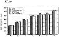
- FIG. 9 shows the results of indirect measurement of film thickness t p of samples A to G that have previously been illustrated in Table 1 based on the spectral reflectance ("spectral measurement" in FIG. 9 ).
- samples A, B, F and G are reference samples
- quadratic polynomials are determined from the values of film thickness t p and X and Y which are determined from SEM images of these samples.
- film thickness t p was determined by substituting the values of X and Y in the above quadratic polynomials.
- FIG. 9 shows together a film thickness which was determined from a SEM image and a film thickness which was determined using an ellipsometer.
- the ellipsometer used was a spectral ellipsometry (M-200, rotating compensator type) manufactured by J. A. Woollanm Co. Inc.
- the analysis model was such that the volume ratio of alumina portions and vacancy portions in the porous layer was 50:50, and the boundary region between the barrier layer and the aluminum layer was a 30 nm thick layer.
- the thicknesses of samples C, D, and E which are determined by spectroscopy accord very well with the thicknesses determined from the SEM images. Note that the reason why they do not exactly accord is that only a local thickness is determined from a SEM image, whereas the spectroscopy provides the average value across a certain extent of area. On the other hand, the film thickness which is determined using an ellipsometer has a large variation. It is sometimes larger, and at other times smaller, than the thickness which is determined from a SEM image. Thus, the measurement accuracy is poor.
- employing an inspection method of an embodiment of the present invention enables to nondestructively and readily inspect whether or not a minute uneven structure at the surface of a porous alumina layer is within a predetermined range.
- an inspection method of an embodiment of the present invention enables stable mass-production of a moth-eye mold that includes a porous alumina layer which is for production of an antireflection film.
- an antireflection film can be produced as described below.
- the surface of the porous alumina layer of a mold that is manufactured as described above is provided with a mold release treatment.
- a polymer film e.g., TAC film
- a photocurable resin typically, acrylic UV-curable resin
- the uneven surface of the porous alumina layer which has been provided with a mold release treatment is pressed against the photocurable resin in vacuum.
- the photocurable resin that fills the uneven structure of the porous alumina layer is irradiated with ultraviolet light such that the photocurable resin is cured.
- the moth-eye mold is released from the polymer film, so that a cured material layer of the photocurable resin (antireflection film), to which the uneven structure of the moth-eye mold has been transferred, is obtained over the surface of the polymer film.
- an antireflection film can be continuously formed over the surface of a polymer film that is in the form of a roll according to a roll-to-roll method.
- the reflectance of the thus-formed antireflection film is, for example, not more than 0.2% at 550 nm.
- the present invention is suitably used for, for example, inspection of a moth-eye mold that includes a porous alumina layer which is for production of an antireflection film.
- the present invention is used for inspection of a porous alumina layer which is employed in other uses, for example, inspection of a porous alumina layer which has regularly-arranged cylindrical recessed portions.
Landscapes
- Physics & Mathematics (AREA)
- General Physics & Mathematics (AREA)
- Spectroscopy & Molecular Physics (AREA)
- Biochemistry (AREA)
- Chemical & Material Sciences (AREA)
- Analytical Chemistry (AREA)
- Life Sciences & Earth Sciences (AREA)
- General Health & Medical Sciences (AREA)
- Immunology (AREA)
- Pathology (AREA)
- Health & Medical Sciences (AREA)
- Investigating Or Analysing Materials By Optical Means (AREA)
- Length Measuring Devices By Optical Means (AREA)
- Laminated Bodies (AREA)
Claims (7)
- Procédé pour inspecter un moule, le procédé comprenant les étapes suivantes :(a) la fourniture, sur la base d'une relation entre des premières valeurs de paramètre indiquant des épaisseurs de couches poreuses en alumine et des valeurs de paramètre de couleur indiquant des couleurs d'une lumière réfléchie par des couches poreuses en alumine, de premières informations de couleur qui représentent une plage de tolérance du premier paramètre pour des couches poreuses en alumine ayant une structure irrégulière avec des paramètres de structure au sein de la plage de tolérance ;(b) la fourniture du moule qui est un sujet d'inspection, le moule ayant une couche poreuse en alumine sur sa surface ;(c) l'obtention d'un paramètre de couleur qui indique une couleur d'une lumière réfléchie par la couche poreuse en alumine du moule soumis à une inspection ; et(d) la détermination d'un caractère approprié du premier paramètre du moule soumis à une inspection sur la base du paramètre de couleur obtenu et des premières informations de couleur.
- Procédé selon la revendication 1, dans lequel le paramètre de couleur inclut X ou Y des composantes trichromatiques X, Y et Z.
- Procédé selon la revendication 2, dans lequel l'étape (a) inclut l'expression de la relation du premier paramètre et de X ou Y en tant que formule d'approximation.
- Procédé selon l'une quelconque des revendications 1 à 3, dans lequel l'étape (c) inclut la mesure d'une réflectance spectrale de la couche poreuse en alumine du moule soumis à une inspection.
- Procédé selon l'une quelconque des revendications 1 à 4, dans lequell'étape (c) inclut l'obtention du paramètre de couleur à partir de chacune d'une pluralité de différentes positions sur une surface de la couche poreuse en alumine, etl'étape (d) inclut la détermination d'un caractère approprié du premier paramètre du moule soumis à une inspection sur la base du paramètre de couleur obtenu à partir de chacune de la pluralité de différentes positions et des premières informations de couleur.
- Procédé selon la revendication 5, comprenant en outre l'étape suivante :
(e) la détermination d'un caractère approprié du premier paramètre du moule soumis à une inspection sur la base d'une relation entre une position sur une surface de la couche poreuse en alumine et le premier paramètre. - Procédé selon l'une quelconque des revendications 1 à 6, comprenant en outre les étapes suivantes :(f) la fourniture, sur la base d'une relation entre un second paramètre qui indique une occupation de la pluralité de minuscules parties évidées de la couche poreuse en alumine et un paramètre de couleur qui indique une couleur d'une lumière réfléchie par la couche poreuse en alumine, de secondes informations de couleur qui représentent une tolérance du second paramètre d'une couche poreuse en alumine qui présente une structure irrégulière qui est à l'intérieur d'une tolérance ; et(g) la détermination d'une validité du second paramètre du moule soumis à une inspection sur la base du paramètre de couleur obtenu et des secondes informations de couleur.
Applications Claiming Priority (2)
| Application Number | Priority Date | Filing Date | Title |
|---|---|---|---|
| JP2010115733 | 2010-05-19 | ||
| PCT/JP2011/061337 WO2011145625A1 (fr) | 2010-05-19 | 2011-05-17 | Procédé d'inspection de filière |
Publications (3)
| Publication Number | Publication Date |
|---|---|
| EP2573545A1 EP2573545A1 (fr) | 2013-03-27 |
| EP2573545A4 EP2573545A4 (fr) | 2017-03-29 |
| EP2573545B1 true EP2573545B1 (fr) | 2019-07-03 |
Family
ID=44991727
Family Applications (1)
| Application Number | Title | Priority Date | Filing Date |
|---|---|---|---|
| EP11783559.5A Active EP2573545B1 (fr) | 2010-05-19 | 2011-05-17 | Procédé d'inspection de filière |
Country Status (7)
| Country | Link |
|---|---|
| US (1) | US8760655B2 (fr) |
| EP (1) | EP2573545B1 (fr) |
| JP (1) | JP5059985B2 (fr) |
| CN (1) | CN102893140B (fr) |
| BR (1) | BR112012029474A2 (fr) |
| RU (1) | RU2515123C1 (fr) |
| WO (1) | WO2011145625A1 (fr) |
Families Citing this family (7)
| Publication number | Priority date | Publication date | Assignee | Title |
|---|---|---|---|---|
| JP5728089B2 (ja) * | 2011-07-08 | 2015-06-03 | シャープ株式会社 | 形状検査方法、構造物の製造方法及び形状検査装置 |
| TWI529385B (zh) * | 2011-09-26 | 2016-04-11 | 三菱麗陽股份有限公司 | 表面具有微細凹凸結構之構件的檢查裝置及檢查方法、表面具有陽極氧化氧化鋁層的構件的製造方法以及光學膜的製造方法 |
| JP6140990B2 (ja) * | 2012-11-30 | 2017-06-07 | キヤノン株式会社 | 測定装置、インプリントシステム、測定方法及びデバイス製造方法 |
| US10107574B2 (en) | 2014-08-07 | 2018-10-23 | Sharp Kabushiki Kaisha | Heat exchanger including fins with surface having bactericidal activity, metallic member with surface having bactericidal activity, method for inhibiting mold growth and sterilization method both using surface of fins of heat exchanger or surface of metallic member, and electrical water boiler, beverage supplier, and lunch box lid all including metallic member |
| WO2018017032A1 (fr) * | 2016-07-21 | 2018-01-25 | Assan Alümi̇nyum San. Ve Ti̇c. A. Ş. | Mesure de l'épaisseur d'oxyde sur une surface d'aluminium par spectroscopie ftir et procédé chimiométrique |
| US10161859B2 (en) | 2016-10-27 | 2018-12-25 | Honeywell International Inc. | Planar reflective ring |
| JP6988669B2 (ja) * | 2018-04-24 | 2022-01-05 | 株式会社デンソー | レーザ照射されたニッケル膜の検査方法 |
Family Cites Families (20)
| Publication number | Priority date | Publication date | Assignee | Title |
|---|---|---|---|---|
| DE19708776C1 (de) | 1997-03-04 | 1998-06-18 | Fraunhofer Ges Forschung | Entspiegelungsschicht sowie Verfahren zur Herstellung derselben |
| RU2150533C1 (ru) * | 1999-02-08 | 2000-06-10 | Мирзоев Рустам Аминович | Способ формирования объемно-пористого слоя металла с открытой пористостью на электропроводной подложке |
| US7066234B2 (en) | 2001-04-25 | 2006-06-27 | Alcove Surfaces Gmbh | Stamping tool, casting mold and methods for structuring a surface of a work piece |
| DE10020877C1 (de) * | 2000-04-28 | 2001-10-25 | Alcove Surfaces Gmbh | Prägewerkzeug, Verfahren zum Herstellen desselben, Verfahren zur Strukturierung einer Oberfläche eines Werkstücks und Verwendung einer anodisch oxidierten Oberflächenschicht |
| US7365860B2 (en) * | 2000-12-21 | 2008-04-29 | Sensory Analytics | System capable of determining applied and anodized coating thickness of a coated-anodized product |
| JP4406553B2 (ja) | 2003-11-21 | 2010-01-27 | 財団法人神奈川科学技術アカデミー | 反射防止膜の製造方法 |
| JP2005171306A (ja) * | 2003-12-10 | 2005-06-30 | Fuji Photo Film Co Ltd | 金属微粒子層の作製方法 |
| JP2005173120A (ja) * | 2003-12-10 | 2005-06-30 | Fuji Photo Film Co Ltd | 低反射構造体および低反射構造体の作製方法 |
| JP2005200679A (ja) * | 2004-01-13 | 2005-07-28 | Fuji Photo Film Co Ltd | 微細構造体からなる光学素子 |
| JP4579593B2 (ja) | 2004-03-05 | 2010-11-10 | キヤノン株式会社 | 標的物質認識素子、検出方法及び装置 |
| WO2006059686A1 (fr) * | 2004-12-03 | 2006-06-08 | Sharp Kabushiki Kaisha | Materiau empechant la reflexion, element optique, dispositif d’affichage, procede de fabrication d’une matrice et procede de fabrication d’un materiau empechant la reflexion a l’aide de la matrice |
| CN101203741B (zh) | 2005-06-14 | 2012-01-18 | 富士胶片株式会社 | 传感器、多通道传感器、感测设备和感测方法 |
| JP2007024869A (ja) * | 2005-06-14 | 2007-02-01 | Fujifilm Holdings Corp | マルチチャンネルセンサ、センシング装置、及びセンシング方法 |
| JP4955240B2 (ja) * | 2005-09-02 | 2012-06-20 | パナソニック株式会社 | 膜測定装置およびそれを用いる塗工装置 |
| JP2008011471A (ja) * | 2006-06-30 | 2008-01-17 | Kyocera Kinseki Corp | 圧電発振器 |
| US20080020724A1 (en) * | 2006-07-19 | 2008-01-24 | John Robert Orrell | Establishing a data link between stacked cargo containers |
| RU2324015C1 (ru) * | 2006-12-15 | 2008-05-10 | Государственное образовательное учреждение высшего профессионального образования Московский государственный институт электронной техники (технический университет) | Способ получения пористого анодного оксида алюминия |
| JP2008205188A (ja) * | 2007-02-20 | 2008-09-04 | Mitsubishi Heavy Ind Ltd | 膜厚計測方法及びその装置ならびに薄膜製造システム |
| JP4460020B2 (ja) * | 2009-09-11 | 2010-05-12 | 財団法人神奈川科学技術アカデミー | 陽極酸化ポーラスアルミナからなる鋳型及びその製造方法 |
| JP4595044B2 (ja) * | 2009-12-16 | 2010-12-08 | 財団法人神奈川科学技術アカデミー | 陽極酸化ポーラスアルミナからなる鋳型及びその製造方法 |
-
2011
- 2011-05-17 CN CN201180024605.9A patent/CN102893140B/zh active Active
- 2011-05-17 RU RU2012154909/28A patent/RU2515123C1/ru active
- 2011-05-17 BR BR112012029474A patent/BR112012029474A2/pt not_active IP Right Cessation
- 2011-05-17 JP JP2012515897A patent/JP5059985B2/ja not_active Expired - Fee Related
- 2011-05-17 EP EP11783559.5A patent/EP2573545B1/fr active Active
- 2011-05-17 WO PCT/JP2011/061337 patent/WO2011145625A1/fr not_active Ceased
- 2011-05-17 US US13/698,395 patent/US8760655B2/en active Active
Non-Patent Citations (1)
| Title |
|---|
| None * |
Also Published As
| Publication number | Publication date |
|---|---|
| RU2515123C1 (ru) | 2014-05-10 |
| JP5059985B2 (ja) | 2012-10-31 |
| WO2011145625A1 (fr) | 2011-11-24 |
| EP2573545A4 (fr) | 2017-03-29 |
| BR112012029474A2 (pt) | 2017-01-24 |
| CN102893140B (zh) | 2014-10-22 |
| US20130063725A1 (en) | 2013-03-14 |
| US8760655B2 (en) | 2014-06-24 |
| JPWO2011145625A1 (ja) | 2013-07-22 |
| EP2573545A1 (fr) | 2013-03-27 |
| CN102893140A (zh) | 2013-01-23 |
Similar Documents
| Publication | Publication Date | Title |
|---|---|---|
| EP2573545B1 (fr) | Procédé d'inspection de filière | |
| US8747683B2 (en) | Die for moth-eye, and method for producing die for moth-eye and moth-eye structure | |
| US9127371B2 (en) | Mold and production method for same, and anti-reflection film | |
| CN102844473B (zh) | 阳极氧化铝的制造方法、检查装置以及检查方法 | |
| RU2734097C2 (ru) | Калибровочный слайд для цифровой патологии | |
| EP2426237A1 (fr) | Moule et procédé de fabrication de celui-ci | |
| CN103842803B (zh) | 检查装置及检查方法、构件的制法及光学薄膜的制法 | |
| Kushnir et al. | Anodizing with voltage versus optical path length modulation: a new tool for the preparation of photonic structures | |
| CN111266934B (zh) | 一种离子束抛光单片集成Fabry-Pérot腔全彩滤光片大批量制造方法 | |
| US10695955B2 (en) | Mold manufacturing method and anti-reflective film manufacturing method | |
| JP5728089B2 (ja) | 形状検査方法、構造物の製造方法及び形状検査装置 | |
| Saito et al. | Morpho blue reproduced by nanocasting lithography | |
| CN116625275A (zh) | 一种基于光场信息融合的超薄多层图形微纳结构三维重构方法 | |
| Shaban | Effect of pore thickness and the state of polarization on the optical properties of hexagonal nanoarray of Au/nanoporous anodic alumina membrane | |
| CN114415280B (zh) | 一种利用等离子体刻蚀调控有机薄膜光谱颜色的方法 | |
| Kee et al. | Plasmonic nanohole array for biosensor applications | |
| JP2012135946A (ja) | 微細凹凸構造を表面に有する物品の製造方法および製造装置 | |
| Riesebeck et al. | Investigation of perovskite layer growth from solution on textured substrates | |
| JP5899638B2 (ja) | 反射防止フィルム製造用金型の製造方法 | |
| KR102202789B1 (ko) | 3층 구조의 연료전지용 수소이온교환 강화막 비파괴 두께 측정 방법 | |
| Zavalistyi et al. | The structure of oxide film on the porous silicon surface |
Legal Events
| Date | Code | Title | Description |
|---|---|---|---|
| PUAI | Public reference made under article 153(3) epc to a published international application that has entered the european phase |
Free format text: ORIGINAL CODE: 0009012 |
|
| 17P | Request for examination filed |
Effective date: 20121127 |
|
| AK | Designated contracting states |
Kind code of ref document: A1 Designated state(s): AL AT BE BG CH CY CZ DE DK EE ES FI FR GB GR HR HU IE IS IT LI LT LU LV MC MK MT NL NO PL PT RO RS SE SI SK SM TR |
|
| DAX | Request for extension of the european patent (deleted) | ||
| RA4 | Supplementary search report drawn up and despatched (corrected) |
Effective date: 20170228 |
|
| RIC1 | Information provided on ipc code assigned before grant |
Ipc: G01N 21/29 20060101AFI20170222BHEP |
|
| STAA | Information on the status of an ep patent application or granted ep patent |
Free format text: STATUS: EXAMINATION IS IN PROGRESS |
|
| 17Q | First examination report despatched |
Effective date: 20180129 |
|
| REG | Reference to a national code |
Ref country code: DE Ref legal event code: R079 Ref document number: 602011060222 Country of ref document: DE Free format text: PREVIOUS MAIN CLASS: G01N0021270000 Ipc: G01N0021290000 |
|
| RIC1 | Information provided on ipc code assigned before grant |
Ipc: G01N 21/88 20060101ALI20181114BHEP Ipc: G01N 21/29 20060101AFI20181114BHEP |
|
| GRAP | Despatch of communication of intention to grant a patent |
Free format text: ORIGINAL CODE: EPIDOSNIGR1 |
|
| STAA | Information on the status of an ep patent application or granted ep patent |
Free format text: STATUS: GRANT OF PATENT IS INTENDED |
|
| INTG | Intention to grant announced |
Effective date: 20181221 |
|
| RIN1 | Information on inventor provided before grant (corrected) |
Inventor name: HAYASHI, HIDEKAZU Inventor name: IMAOKU, TAKAO |
|
| GRAS | Grant fee paid |
Free format text: ORIGINAL CODE: EPIDOSNIGR3 |
|
| GRAA | (expected) grant |
Free format text: ORIGINAL CODE: 0009210 |
|
| STAA | Information on the status of an ep patent application or granted ep patent |
Free format text: STATUS: THE PATENT HAS BEEN GRANTED |
|
| AK | Designated contracting states |
Kind code of ref document: B1 Designated state(s): AL AT BE BG CH CY CZ DE DK EE ES FI FR GB GR HR HU IE IS IT LI LT LU LV MC MK MT NL NO PL PT RO RS SE SI SK SM TR |
|
| REG | Reference to a national code |
Ref country code: GB Ref legal event code: FG4D |
|
| REG | Reference to a national code |
Ref country code: CH Ref legal event code: EP Ref country code: AT Ref legal event code: REF Ref document number: 1151596 Country of ref document: AT Kind code of ref document: T Effective date: 20190715 |
|
| REG | Reference to a national code |
Ref country code: DE Ref legal event code: R096 Ref document number: 602011060222 Country of ref document: DE |
|
| REG | Reference to a national code |
Ref country code: IE Ref legal event code: FG4D |
|
| REG | Reference to a national code |
Ref country code: NL Ref legal event code: MP Effective date: 20190703 |
|
| REG | Reference to a national code |
Ref country code: LT Ref legal event code: MG4D |
|
| REG | Reference to a national code |
Ref country code: AT Ref legal event code: MK05 Ref document number: 1151596 Country of ref document: AT Kind code of ref document: T Effective date: 20190703 |
|
| PG25 | Lapsed in a contracting state [announced via postgrant information from national office to epo] |
Ref country code: FI Free format text: LAPSE BECAUSE OF FAILURE TO SUBMIT A TRANSLATION OF THE DESCRIPTION OR TO PAY THE FEE WITHIN THE PRESCRIBED TIME-LIMIT Effective date: 20190703 Ref country code: PT Free format text: LAPSE BECAUSE OF FAILURE TO SUBMIT A TRANSLATION OF THE DESCRIPTION OR TO PAY THE FEE WITHIN THE PRESCRIBED TIME-LIMIT Effective date: 20191104 Ref country code: CZ Free format text: LAPSE BECAUSE OF FAILURE TO SUBMIT A TRANSLATION OF THE DESCRIPTION OR TO PAY THE FEE WITHIN THE PRESCRIBED TIME-LIMIT Effective date: 20190703 Ref country code: LT Free format text: LAPSE BECAUSE OF FAILURE TO SUBMIT A TRANSLATION OF THE DESCRIPTION OR TO PAY THE FEE WITHIN THE PRESCRIBED TIME-LIMIT Effective date: 20190703 Ref country code: NL Free format text: LAPSE BECAUSE OF FAILURE TO SUBMIT A TRANSLATION OF THE DESCRIPTION OR TO PAY THE FEE WITHIN THE PRESCRIBED TIME-LIMIT Effective date: 20190703 Ref country code: AT Free format text: LAPSE BECAUSE OF FAILURE TO SUBMIT A TRANSLATION OF THE DESCRIPTION OR TO PAY THE FEE WITHIN THE PRESCRIBED TIME-LIMIT Effective date: 20190703 Ref country code: BG Free format text: LAPSE BECAUSE OF FAILURE TO SUBMIT A TRANSLATION OF THE DESCRIPTION OR TO PAY THE FEE WITHIN THE PRESCRIBED TIME-LIMIT Effective date: 20191003 Ref country code: NO Free format text: LAPSE BECAUSE OF FAILURE TO SUBMIT A TRANSLATION OF THE DESCRIPTION OR TO PAY THE FEE WITHIN THE PRESCRIBED TIME-LIMIT Effective date: 20191003 Ref country code: HR Free format text: LAPSE BECAUSE OF FAILURE TO SUBMIT A TRANSLATION OF THE DESCRIPTION OR TO PAY THE FEE WITHIN THE PRESCRIBED TIME-LIMIT Effective date: 20190703 Ref country code: SE Free format text: LAPSE BECAUSE OF FAILURE TO SUBMIT A TRANSLATION OF THE DESCRIPTION OR TO PAY THE FEE WITHIN THE PRESCRIBED TIME-LIMIT Effective date: 20190703 |
|
| PG25 | Lapsed in a contracting state [announced via postgrant information from national office to epo] |
Ref country code: RS Free format text: LAPSE BECAUSE OF FAILURE TO SUBMIT A TRANSLATION OF THE DESCRIPTION OR TO PAY THE FEE WITHIN THE PRESCRIBED TIME-LIMIT Effective date: 20190703 Ref country code: IS Free format text: LAPSE BECAUSE OF FAILURE TO SUBMIT A TRANSLATION OF THE DESCRIPTION OR TO PAY THE FEE WITHIN THE PRESCRIBED TIME-LIMIT Effective date: 20191103 Ref country code: AL Free format text: LAPSE BECAUSE OF FAILURE TO SUBMIT A TRANSLATION OF THE DESCRIPTION OR TO PAY THE FEE WITHIN THE PRESCRIBED TIME-LIMIT Effective date: 20190703 Ref country code: ES Free format text: LAPSE BECAUSE OF FAILURE TO SUBMIT A TRANSLATION OF THE DESCRIPTION OR TO PAY THE FEE WITHIN THE PRESCRIBED TIME-LIMIT Effective date: 20190703 Ref country code: GR Free format text: LAPSE BECAUSE OF FAILURE TO SUBMIT A TRANSLATION OF THE DESCRIPTION OR TO PAY THE FEE WITHIN THE PRESCRIBED TIME-LIMIT Effective date: 20191004 Ref country code: LV Free format text: LAPSE BECAUSE OF FAILURE TO SUBMIT A TRANSLATION OF THE DESCRIPTION OR TO PAY THE FEE WITHIN THE PRESCRIBED TIME-LIMIT Effective date: 20190703 |
|
| PG25 | Lapsed in a contracting state [announced via postgrant information from national office to epo] |
Ref country code: TR Free format text: LAPSE BECAUSE OF FAILURE TO SUBMIT A TRANSLATION OF THE DESCRIPTION OR TO PAY THE FEE WITHIN THE PRESCRIBED TIME-LIMIT Effective date: 20190703 |
|
| PG25 | Lapsed in a contracting state [announced via postgrant information from national office to epo] |
Ref country code: EE Free format text: LAPSE BECAUSE OF FAILURE TO SUBMIT A TRANSLATION OF THE DESCRIPTION OR TO PAY THE FEE WITHIN THE PRESCRIBED TIME-LIMIT Effective date: 20190703 Ref country code: PL Free format text: LAPSE BECAUSE OF FAILURE TO SUBMIT A TRANSLATION OF THE DESCRIPTION OR TO PAY THE FEE WITHIN THE PRESCRIBED TIME-LIMIT Effective date: 20190703 Ref country code: IT Free format text: LAPSE BECAUSE OF FAILURE TO SUBMIT A TRANSLATION OF THE DESCRIPTION OR TO PAY THE FEE WITHIN THE PRESCRIBED TIME-LIMIT Effective date: 20190703 Ref country code: DK Free format text: LAPSE BECAUSE OF FAILURE TO SUBMIT A TRANSLATION OF THE DESCRIPTION OR TO PAY THE FEE WITHIN THE PRESCRIBED TIME-LIMIT Effective date: 20190703 Ref country code: RO Free format text: LAPSE BECAUSE OF FAILURE TO SUBMIT A TRANSLATION OF THE DESCRIPTION OR TO PAY THE FEE WITHIN THE PRESCRIBED TIME-LIMIT Effective date: 20190703 |
|
| PG25 | Lapsed in a contracting state [announced via postgrant information from national office to epo] |
Ref country code: SK Free format text: LAPSE BECAUSE OF FAILURE TO SUBMIT A TRANSLATION OF THE DESCRIPTION OR TO PAY THE FEE WITHIN THE PRESCRIBED TIME-LIMIT Effective date: 20190703 Ref country code: IS Free format text: LAPSE BECAUSE OF FAILURE TO SUBMIT A TRANSLATION OF THE DESCRIPTION OR TO PAY THE FEE WITHIN THE PRESCRIBED TIME-LIMIT Effective date: 20200224 Ref country code: SM Free format text: LAPSE BECAUSE OF FAILURE TO SUBMIT A TRANSLATION OF THE DESCRIPTION OR TO PAY THE FEE WITHIN THE PRESCRIBED TIME-LIMIT Effective date: 20190703 |
|
| REG | Reference to a national code |
Ref country code: DE Ref legal event code: R097 Ref document number: 602011060222 Country of ref document: DE |
|
| PLBE | No opposition filed within time limit |
Free format text: ORIGINAL CODE: 0009261 |
|
| STAA | Information on the status of an ep patent application or granted ep patent |
Free format text: STATUS: NO OPPOSITION FILED WITHIN TIME LIMIT |
|
| PG2D | Information on lapse in contracting state deleted |
Ref country code: IS |
|
| 26N | No opposition filed |
Effective date: 20200603 |
|
| PG25 | Lapsed in a contracting state [announced via postgrant information from national office to epo] |
Ref country code: SI Free format text: LAPSE BECAUSE OF FAILURE TO SUBMIT A TRANSLATION OF THE DESCRIPTION OR TO PAY THE FEE WITHIN THE PRESCRIBED TIME-LIMIT Effective date: 20190703 |
|
| PG25 | Lapsed in a contracting state [announced via postgrant information from national office to epo] |
Ref country code: MC Free format text: LAPSE BECAUSE OF FAILURE TO SUBMIT A TRANSLATION OF THE DESCRIPTION OR TO PAY THE FEE WITHIN THE PRESCRIBED TIME-LIMIT Effective date: 20190703 Ref country code: CH Free format text: LAPSE BECAUSE OF NON-PAYMENT OF DUE FEES Effective date: 20200531 Ref country code: LI Free format text: LAPSE BECAUSE OF NON-PAYMENT OF DUE FEES Effective date: 20200531 |
|
| REG | Reference to a national code |
Ref country code: BE Ref legal event code: MM Effective date: 20200531 |
|
| GBPC | Gb: european patent ceased through non-payment of renewal fee |
Effective date: 20200517 |
|
| PG25 | Lapsed in a contracting state [announced via postgrant information from national office to epo] |
Ref country code: LU Free format text: LAPSE BECAUSE OF NON-PAYMENT OF DUE FEES Effective date: 20200517 |
|
| PG25 | Lapsed in a contracting state [announced via postgrant information from national office to epo] |
Ref country code: GB Free format text: LAPSE BECAUSE OF NON-PAYMENT OF DUE FEES Effective date: 20200517 Ref country code: FR Free format text: LAPSE BECAUSE OF NON-PAYMENT OF DUE FEES Effective date: 20200531 Ref country code: IE Free format text: LAPSE BECAUSE OF NON-PAYMENT OF DUE FEES Effective date: 20200517 |
|
| PG25 | Lapsed in a contracting state [announced via postgrant information from national office to epo] |
Ref country code: BE Free format text: LAPSE BECAUSE OF NON-PAYMENT OF DUE FEES Effective date: 20200531 |
|
| PG25 | Lapsed in a contracting state [announced via postgrant information from national office to epo] |
Ref country code: MT Free format text: LAPSE BECAUSE OF FAILURE TO SUBMIT A TRANSLATION OF THE DESCRIPTION OR TO PAY THE FEE WITHIN THE PRESCRIBED TIME-LIMIT Effective date: 20190703 Ref country code: CY Free format text: LAPSE BECAUSE OF FAILURE TO SUBMIT A TRANSLATION OF THE DESCRIPTION OR TO PAY THE FEE WITHIN THE PRESCRIBED TIME-LIMIT Effective date: 20190703 |
|
| PG25 | Lapsed in a contracting state [announced via postgrant information from national office to epo] |
Ref country code: MK Free format text: LAPSE BECAUSE OF FAILURE TO SUBMIT A TRANSLATION OF THE DESCRIPTION OR TO PAY THE FEE WITHIN THE PRESCRIBED TIME-LIMIT Effective date: 20190703 |
|
| REG | Reference to a national code |
Ref country code: DE Ref legal event code: R081 Ref document number: 602011060222 Country of ref document: DE Owner name: SHARP KABUSHIKI KAISHA, SAKAI CITY, JP Free format text: FORMER OWNER: SHARP KABUSHIKI KAISHA, OSAKA, JP |
|
| P01 | Opt-out of the competence of the unified patent court (upc) registered |
Effective date: 20230524 |
|
| PGFP | Annual fee paid to national office [announced via postgrant information from national office to epo] |
Ref country code: DE Payment date: 20230519 Year of fee payment: 13 |
|
| REG | Reference to a national code |
Ref country code: DE Ref legal event code: R119 Ref document number: 602011060222 Country of ref document: DE |
|
| PG25 | Lapsed in a contracting state [announced via postgrant information from national office to epo] |
Ref country code: DE Free format text: LAPSE BECAUSE OF NON-PAYMENT OF DUE FEES Effective date: 20241203 |