EP2573584A1 - Generische Oberflächeneigenschaftsextraktion aus einem Bereichsdatensatz - Google Patents
Generische Oberflächeneigenschaftsextraktion aus einem Bereichsdatensatz Download PDFInfo
- Publication number
- EP2573584A1 EP2573584A1 EP12185317A EP12185317A EP2573584A1 EP 2573584 A1 EP2573584 A1 EP 2573584A1 EP 12185317 A EP12185317 A EP 12185317A EP 12185317 A EP12185317 A EP 12185317A EP 2573584 A1 EP2573584 A1 EP 2573584A1
- Authority
- EP
- European Patent Office
- Prior art keywords
- range data
- features
- points
- range
- surface features
- Prior art date
- Legal status (The legal status is an assumption and is not a legal conclusion. Google has not performed a legal analysis and makes no representation as to the accuracy of the status listed.)
- Ceased
Links
Images




Classifications
-
- G—PHYSICS
- G01—MEASURING; TESTING
- G01S—RADIO DIRECTION-FINDING; RADIO NAVIGATION; DETERMINING DISTANCE OR VELOCITY BY USE OF RADIO WAVES; LOCATING OR PRESENCE-DETECTING BY USE OF THE REFLECTION OR RERADIATION OF RADIO WAVES; ANALOGOUS ARRANGEMENTS USING OTHER WAVES
- G01S17/00—Systems using the reflection or reradiation of electromagnetic waves other than radio waves, e.g. lidar systems
- G01S17/88—Lidar systems specially adapted for specific applications
- G01S17/89—Lidar systems specially adapted for specific applications for mapping or imaging
-
- G—PHYSICS
- G06—COMPUTING OR CALCULATING; COUNTING
- G06T—IMAGE DATA PROCESSING OR GENERATION, IN GENERAL
- G06T7/00—Image analysis
- G06T7/10—Segmentation; Edge detection
- G06T7/12—Edge-based segmentation
-
- G—PHYSICS
- G06—COMPUTING OR CALCULATING; COUNTING
- G06T—IMAGE DATA PROCESSING OR GENERATION, IN GENERAL
- G06T7/00—Image analysis
- G06T7/70—Determining position or orientation of objects or cameras
- G06T7/73—Determining position or orientation of objects or cameras using feature-based methods
-
- G—PHYSICS
- G01—MEASURING; TESTING
- G01S—RADIO DIRECTION-FINDING; RADIO NAVIGATION; DETERMINING DISTANCE OR VELOCITY BY USE OF RADIO WAVES; LOCATING OR PRESENCE-DETECTING BY USE OF THE REFLECTION OR RERADIATION OF RADIO WAVES; ANALOGOUS ARRANGEMENTS USING OTHER WAVES
- G01S17/00—Systems using the reflection or reradiation of electromagnetic waves other than radio waves, e.g. lidar systems
- G01S17/87—Combinations of systems using electromagnetic waves other than radio waves
- G01S17/875—Combinations of systems using electromagnetic waves other than radio waves for determining attitude
-
- G—PHYSICS
- G06—COMPUTING OR CALCULATING; COUNTING
- G06T—IMAGE DATA PROCESSING OR GENERATION, IN GENERAL
- G06T2207/00—Indexing scheme for image analysis or image enhancement
- G06T2207/10—Image acquisition modality
- G06T2207/10028—Range image; Depth image; 3D point clouds
Definitions
- a global navigation satellite system such as the Global Positioning System (GPS)
- GPS Global Positioning System
- INS inertial navigation system
- a range finder can be used as an aiding source to address the drift.
- a range finder can provide 3D range data corresponding to a distance between the range finder and objects in front of the range finder. Features can be extracted from the 3D range data to aid the INS.
- An example embodiment includes a method including receiving a three-dimensional set of range data including a plurality of points from one or more range finders. The method also includes extracting one or more surface features. Extracting includes segmenting the set of range data into a plurality of surfaces based on one or more edges, selecting one or more of the plurality of surfaces as the one or more surface features, and describing the one or more surface features based on a generic descriptor that can describe both planar and non-planar surface features.
- the method can also include using the one or more surface features to calculate one of a relative angle and orientation between the set of range data and at least one other set of range data, a rotation and translation of an object in the set of range data with respect to the object in at least one other set of range data, a rotation and translation between the set of range data with and at least one other set of range data, or a navigation solution based on the set of range data and at least one other set of range data.
- Figure 1 is a block diagram of an example navigation system.
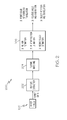
- Figure 2 is a flow diagram of an example method for motion estimation for which the navigation system of Figure 1 can be configured to perform.
- Figure 3 is a flow diagram of an example method for estimating motion for which the navigation system of Figure 1 can be configured to perform.
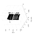
- Figure 4A is a graph of an example organized set of range data, wherein the organized set of range data is rendered based on the range of each point.
- Figure 4B is a graph of an example of the organized set of range data of Figure 4A after pre-processing.
- Figure 5 is a flow diagram of an example method for edge detection, segmentation, and feature extraction for which the navigation system of Figure 1 can be configured to perform.
- Figure 6A is a graph of an example of the organized set of range data of Figure 4A showing a surface feature and a point feature.
- Figure 6B is a graph of an example of a residual map of the organized set of range data of Figure 6A showing a surface feature and a point feature.
- Figure 7 is a block diagram of an example method for navigation using the feature matches identified by the method of Figure 3 .
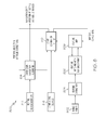
- Figure 8 is a block diagram of an example method for simultaneous localization and mapping (SLAM) using the feature matches identified by the method of Figure 3 .
- SLAM simultaneous localization and mapping
- the present inventors have recognized, among other things, that existing methods of feature extraction can rely on one or more specific geometric models (e.g., a plane, sphere) to represent features in the 3D range data. If the 3D range data does not fit into one of the available geometric models, the data is not considered as a feature.
- Geometric models can be environment specific. A model suitable for one environment may not be suitable for another environment.
- an existing method uses plane features. Planes are extracted in two subsequent sets of range data and all possible combinations of pair of planes between the subsequent sets of range data are scored by a distance, which evaluates the similarity of the planes. Several pairs of planes having the smallest score (that are the most similar) are selected as matching.
- plane features can provide acceptable results in indoor and urban outdoor environments. In a nature environment, however, the approach can fail. This is because the presence of significant planes is infrequent in such an environment.
- FIG. 1 is a block diagram of an example navigation system 100.
- the navigation system 100 can include one or more processing devices 102 coupled to one or more memory devices 104.
- the navigation system 100 can comprise a platform (e.g., a physical structure) having a plurality of sensors mounted thereon.
- the plurality of sensors can include one or more range finders 106 (e.g., a light detection and ranging (LIDAR)) coupled to the one or more processing devices 102 and configured to capture range data and provide the range data to the one or more processing devices 102.
- LIDAR light detection and ranging
- the plurality of sensors can also include one or more inertial sensors 108 (e.g., gyroscope, accelerometer, etc.) coupled to the one or more processing devices 102 and configured to sense inertial movement and provide data indicative of the inertial movement to the one or more processing devices 102.
- the plurality of sensors can also include one or more aiding sources 110 (e.g., altimeter, magnetometer, satellite navigation system receiver, etc.) coupled to the one or more processing devices 102 and configured to provide navigation data to the one or more processing devices 102.
- the plurality of sensors mounted on the platform in a stationary physical relationship such that a direction cosine matrix between the sensors is fixed.
- the navigation system 100 can include one or more output devices 112 (e.g., port, display device, speaker, etc.) coupled to the one or more processing devices 102 and configured to provide data to a user or another system.
- the one or more processing devices 102 can include a central processing unit (CPU), microcontroller, microprocessor (e.g., a digital signal processor (DSP)), field programmable gate array (FPGA), application specific integrated circuit (ASIC) and other processing devices.
- the one or more processing devices 102 and the navigation system 100 can be "configured" to perform certain acts when the one or more memory devices 104 include instructions 114 which, when executed by the one or more processing devices 102, cause the one or more processing devices 102 to perform those acts. These instructions can implement the functions of the navigation system 100 as described herein. These instructions can be stored on any appropriate processor-readable medium used for storage of processor-readable instructions and/or data structures.
- This processor-readable medium can include the one or more memory devices 104 and/or other suitable media.
- Suitable processor readable media can include tangible media such as magnetic or optical media.
- tangible media can include a conventional hard disk, compact disk (e.g., read only or rewritable), volatile or non-volatile media such as random access memory (RAM) including, but not limited to, synchronous dynamic random access memory (SDRAM), double data rate (DDR) RAM, RAMBUS dynamic RAM (RDRAM), static RAM (SRAM), etc.), read only memory (ROM), electrically erasable programmable ROM (EEPROM), and flash memory, etc.
- RAM synchronous dynamic random access memory
- DDR double data rate
- RDRAM RAMBUS dynamic RAM
- SRAM static RAM
- ROM read only memory
- EEPROM electrically erasable programmable ROM
- flash memory etc.
- Suitable processor-readable media can also include transmission media such as electrical, electromagnetic, and digital signals, conveyed via a communication medium such as a
- the navigation system 100 can be implemented in an aircraft (e.g., plane, jet, helicopter, etc.), spacecraft, land vehicle (e.g., rover), water vehicle, or other entity (e.g., missile). These entities can be autonomous, semi-autonomous, or human piloted.
- aircraft e.g., plane, jet, helicopter, etc.
- spacecraft e.g., spacecraft
- land vehicle e.g., rover
- water vehicle e.g., missile
- missile e.g., missile
- the following description may refer to the one or more processing devices 102, the one or more memory devices 104, the one or more range finders 106, the one or more inertial sensors 108, one or more aiding sources 110, and the one or more output devices 112 in the singular form (e.g., the processing device 102); however, it should be understood that in many cases the singular form is used for simplicity and that use of the singular form may be not intended to limit these components to a single component (e.g., a single processing device 102) unless otherwise specified. Accordingly, although the singular form is used, it should be understood that in many cases one or more of the particular components can be used as indicated above.
- the instructions 114 can be used in the processing unit 102 to perform a sequence of operations over a plurality of time steps.
- the processing unit 102 can acquire data from various sensors (e.g., inertial sensor 108, range finder 106, and aiding source 110).
- the processing unit 102 can apply a strapdown navigation algorithm to the inertial measurements and apply processing algorithms to the range data acquired from the range finder 106.
- the processing unit 102 can fuse the strapdown algorithm output with the range data and the measurements from the aiding sources 110 to generate estimates of the state of a sensor platform of the navigation system 100. This state can include the three-dimensional (3D) position, velocity, and attitudes.
- the output of the processing unit 102 is the navigation solution (e.g., the state of the sensor platform).
- Figure 2 is a flow diagram of an example method 200 for motion estimation for which the navigation system 100 can be configured to perform.
- the method 200 can also be used for estimating a relative position between a first set of range data and one or more other sets of range data, or to estimate motion of an object in a first set of range data with respect to one or more other sets of range data.
- the instructions 114 can be configured to, when executed by the processing device 102, cause the navigation system 100 to implement method 200.
- the method 200 can include receiving a plurality of sets of range data (e.g., from the range finder 106).
- a set of range data can correspond to a 3D range image or 3D point cloud captured by the range finder 106. That is, a set of range data can correspond to a capture of a given real world scene at a given time by the range finder.
- a plurality of features can be extracted from two or more sets of range data.
- the plurality of features can include one or more point features, one or more edge features, and/or one or more surface features.
- An edge feature can be extracted in any appropriate manner (e.g., using edge based segmentation or region growing).
- a point feature can be extracted based on an intersection of two or more surfaces. Extraction of surface features can be generic such that both planar and non-planar surface features can be extracted if present.
- a point feature can be extracted based on an intersection of three or more surfaces.
- a point feature corresponds to a point having a significant property with respect to a neighborhood of points.
- a point feature might or might not have any direct geometrical interpretation and can be independent of a corner, edge, or surface feature. More detail regarding feature extraction is provided with respect to Figures 3 and 5 .
- a plurality of matching features can be identified between a first set of 3D range data and one or more other sets of 3D range data.
- feature matches can be identified based on a similarity between descriptors for two features.
- the similarity between descriptors can be measured in any appropriate manner including by an information measure such as a norm or a statistical correlation.
- matches between surface features can be identified based on one of the correlation or mutual information between the two surface features.
- the plurality of matching features can be processed to determine a positional relationship between the matching features.
- This positional relationship can be used for one or more of several purposes. For example, if a first set of range data is captured from a first range finder at a first time of a first scene and one or more other sets of range data are captured from the first range finder at a later time of at least a portion of the first scene, the positional relationship can be used to estimate of motion between a first set of range data and one or more other sets of range data. This estimation of motion can be output as a change in rotation and translation between the first set of range data and the one or more other sets of range data. The estimation of motion can then be used to aid in navigational as explained in more detail with respect to Figures 7 and 8 .
- the positional relationship can be used to estimate a relative position between the first range finder and the second range finder.
- a first set of range data is captured from a first range finder at a first time of a first scene and one or more other sets of range data are captured from the first range finder at a later time of at least a portion of the first scene, and an object within the scene has moved relative to other objects, the positional relationship can be used to estimate motion of the object.
- Figure 3 is a flow diagram of an example method 300 for estimating motion with the navigation system 100.
- a set of range data can be captured by a range finder 106.
- the set of range data can include a plurality of points wherein a point includes a range for a given elevation and azimuth from the range finder 106.
- the set of range data can be organized (e.g., tabularized) based on elevation and azimuth for each point.
- the set of range data can be organized into a table of size 64 x 4096, however, the size and shape of the table is based on the number and azimuth for data points captured by the range finder as well as on selected requirements.
- Figure 4A is a graphical example of an organized set of range data, wherein the organized set of range data is rendered based on the range of each point. When illustrated in this way, the object(s) from which the range data was captured can be seen.
- the set of range data can be pre-processed. Pre-processing can exclude one or more areas within the set of range data with a low number of laser returns, a laser return strength below a threshold value, or both. Since measurements (if any) obtained from these areas are likely inaccurate, these areas can be excluded from further processing by removing points corresponding to these areas from the plurality of points or by setting points corresponding to these areas to have no value. In Figure 4A an area in the right center with no data can be observed.
- Pre-processing can also include interpolating the set of range data to estimate a value for one or more points with no value.
- the value of a point with no value can be interpolated based on the values of neighboring points. Interpolating to fill in points with no value may enable fast segmentation using linear operators. This can also include correction of points in case of a broken or malfunctioning range finder.
- Pre-processing can also include filtering the set of range data to suppress noise and to remove outliers.
- Figure 4B is a graphical example of the set of range data in Figure 4A after pre-processing. As can be seen, many of the points with no value have been filled in via interpolation and outliers have been removed.
- Blocks 306, 308, 310, and 312 correspond generally to feature extraction (block 202 of method 200) for the set of range data.
- feature extraction can include extracting one or more surface, edge, and/or point features.
- Feature extraction can include segmentation of the set of range data followed by selection and description of the features.
- Blocks 306 and 308 correspond generally to segmentation of the range data.
- Block 308 also corresponds to selection of surface features, while block 310 corresponds to selection of point and edge features.
- Block 312 corresponds to description of the features that were selected at blocks 308 and 310.
- Edge detection can include classifying the plurality of points of the set of range data into a first set of points corresponding to one or more edges and a second set of points corresponding to one or more surfaces.
- edge detection includes identifying step edges and roof edges within the plurality of points.
- a step edge correspond to an edge between physically separated (e.g., non-intersecting) surfaces and can be identified, for example, based on discontinuity in range values among points.
- a roof edge corresponds to an edge between intersecting surfaces (e.g., wall corners, etc.) such that the edge has continuous range values between surfaces. Roof edges, therefore, can be identified, for example, based on changes in orientation between the surfaces.
- points corresponding to an edge, both step and roof are classified as edge points and all other points are classified as surface points.
- a plurality of surfaces can be identified in the set of range data.
- the plurality of surfaces can be identified based on the classification of edge points and surface points at block 306. For example, once the points are classified as corresponding to an edge or surface, the surface points (i.e., points classified as a surface) are further classified as corresponding to one of a plurality of surfaces in the set of range data. Surface points can be classified as corresponding to a specific surface by identifying areas of surface points that are surrounded by an edge. That is, a group of surface points that have no dividing edges and are surrounded by edge points and the edge of the point cloud can be classified as a single surface. Each of the surface points can be classified in this manner until all surface points have been classified as corresponding to one of a plurality of surfaces in the set of range data.
- Blocks 306 and 308 describe one example of segmentation of the set of range data using an edge-based approach. In other examples, other methods of segmentation can be used including region growing and scanline-based segmentation.
- block 308 can also correspond to selection of surface features.
- a surface identified can be selected as a surface feature based on characteristics of the surface. For example, a distant surface in front of a larger surface can be selected as a surface feature.
- Such a surface feature can be identified based on the surface being substantially surrounded by (e.g., separated by a step edge from) points having generally larger ranges (e.g., corresponding to a second larger surface). Surfaces such as these may make robust features as they can be less prone to occlusions in the subsequent range finder scans.
- point and edge features can be selected.
- Edge features can be selected in any appropriate manner. For example, an intersection of two surfaces can be selected as an edge feature. Point features can be selected based on unique properties with respect to their neighborhoods (e.g., having the highest gradient or other property preferably invariant to rotation and translation). Also, an intersection of three or more surfaces or three or more roof edges can be selected as a point feature corresponding to a corner. A point having some other unique property can also be selected as a point feature. For example, a point surrounded by a single surface (e.g., the point of cone) can also be selected as a point feature. In an example, a point or a small group of points having a sum of residuals that is a threshold amount larger that of surrounding points can be selected as a point feature. The threshold can be 1.5, 3, or another amount times larger than surrounding points.
- a surface feature can be described using a generic descriptor that can describe both planar and non-planar surfaces features.
- a generic descriptor can include a descriptor based on the statistical properties of the subset of points (e.g., mean value, covariance matrix including its eigenvalues and eigenvectors, higher order moments, estimated probability density function), because the surface feature is a subset of (range) points.
- a generic descriptor can include a descriptor based on quantities used in differential geometry such as, but not limited to, various curvature measures.
- a generic descriptor can include a descriptor based on eignevalues of a covariance matrix of points forming the surface feature. Such a descriptor can be used because it is invariant to rotation or translation and can therefore provide a good means for matching surface features captured from different locations.
- a generic descriptor can include a descriptor based on a distance of the surface feature and its neighborhood or other features. For example, a surface feature can be described using an information measure such as mutual information, Kullback-Leibler distance/divergence, Jensen-Shanon divergence, Bhattacharyya distance, Hellinger distance, and the like. Such descriptors can under certain assumptions (e.g., a Gaussian distribution of the range data) be invariant with respect to rotational or translational motion.
- a surface feature selected at block 308 can be described in an object specific manner.
- the surface feature can be recognized as a certain object (e.g., shape) and described in a manner corresponding to the object that is recognized.
- Different objects can have different descriptors such that a first surface feature recognized as a first object can be described according to descriptors corresponding to the first object and a second surface feature recognized as a second object can be described according to descriptors corresponding to the second object.
- the surface feature can be described based on a geometric representation of the object.
- a surface feature recognized as a plane can be described by a normal vector and distance.
- a surface feature recognized as a sphere can be described by center coordinates and a radius.
- a surface feature recognized as an automobile can be described with parameters corresponding to an automobile. Other objects can be recognized.
- a point feature selected at block 310 can be described based on gradient information.
- an edge feature can be described using known edge descriptors.
- Surface, edge, and point features can also be described based on a distance (e.g., information, Euclidian, and the like) with respect to other selected features.
- the extracted features can be used at bock 322 for matching with extracted features from another set of range data.
- the extracted features can also be stored (block 318) for later feature matching at block 322 after processing another set of range data through blocks 302-314. If there are not a sufficient number of features, then the extracted features, if any, can be discarded and the next set of range data can be processed through blocks 302-314. In some examples, even if there are an insufficient number of extracted features, the extracted features can be stored for later use computing a partial navigation solution.
- the extracted features from the two sets of range data can be compared to identify any matching features.
- This comparison of extracted features can be referred to as data association or matching.
- a first set of range data is processed through blocks 302-314 and the extracted features can be stored (block 318).
- a second set of range data is also processed through blocks 302-314.
- the extracted features from the first set of range data can be read (block 320) and can be compared to the extracted features from the first set of range data to identify any matching features.
- matching features can be identified by one-to-one matching (e.g., based-on cross-correlation matching, various norms (e.g., Euclidian), informational measures (e.g., mutual information, Kullback-Leibler distance/divergence, Jensen-Shanon divergence, Bhattacharyya distance, Hellinger distance)).
- matching features can be identified based on a distance between descriptors of the extracted features. For example, a first extracted feature can be considered to match a second extracted feature if the distance (e.g., Euclidian) between the descriptors of the first and second extracted features is below a distance threshold and the distance is the smallest distance as compared to potential matches with other extracted features. In another example, a first extracted feature can be considered to match a second extracted feature if one of the correlation or mutual information between the two extracted features is above a threshold and is the largest as compared to potential matches with other extracted features.
- matching features can be identified by relational matching, in which case no individual descriptors are used. For example, mutual relations (e.g., distance) between groups of features can be used to establish correspondences. Relational matching can match correspondences of multiple pairs of features.
- motion e.g., a full navigation solution
- motion e.g., a full navigation solution
- a sufficient number of pairs of matching features e.g., three pairs
- motion can be estimated at block 326. If a sufficient number of pairs of matching features are not identified, then either motion is not estimated (block 316) or a partial navigation solution can be estimated.
- frame motion, relative position, or object motion can be estimated as described with respect to block 206 of Figure 2 .
- Figure 5 is a flow diagram of an example method 500 for segmentation and surface feature selection with the navigation system 100.
- block 502 corresponds to blocks 302 and 304 of method 300
- blocks 504, 506, and 508 correspond to block 306 of method 300
- blocks 510 and 512 corresponds to block 308 of method 300.
- a set of range data can be captured by a range finder 106 and pre-processed as described with respect to block 304.
- the set of range data can include a plurality of points wherein a point includes a range for a given elevation and azimuth from the range finder 106.
- the set of range data can be organized (e.g., tabularized) based on elevation and azimuth for each point.
- the set of range data can be organized into a table of size 64 x 4096, however, the size and shape of the table is based on the number and direction of data points captured by the range finder.
- Figure 4A is a graphical example of an organized set of range data, wherein the organized set of range data is rendered based on the range of each point. When illustrated in this way, the object(s) from which the range data was captured can be seen.
- the edge detection of blocks 504, 506, and 508 can comprise classifying points of the set of range data as corresponding to an edge (e.g., a step edge, roof edge, or other discontinuity) or a surface (e.g., a smooth and/or continuous surface).
- a point can be classified based on the residuals from fitting a plane to a neighborhood of points surrounding the point.
- a point belonging to a smooth and continuous surface should have small residuals. That is, a plane should fit the surface well.
- a point belonging to an edge should have significantly higher residuals. That is, a plane should not fit well.
- the similarity of the neighborhood of the point and a plane can be computed.
- the similarity is in this example measured by a sum of squared residuals (i.e., the distance between a measured point and a fitted plane). Other measures (e.g., mean or maximal distance, etc.) can be used as well. Points in the set of range data having large value of residuals can be further considered to be edge points with the remaining to be surface points. The description below of blocks 504, 506, and 508 provides additional detail.
- the size of the neighborhood surrounding the point i.e., the window or mask size
- other sizes of neighborhoods either fixed or adaptive can be used.
- an adaptive size can be used to adjust the neighborhood size based on a size of the object, which should be recognizable, and the distance from the range finder 106 to the object.
- an object of size 2x2 meters can produce, for example, 8x10 ⁇ 4 laser returns (points) if the distance between the object and the range finder 106 is, for example, 2 meters.
- a fixed size neighborhood can be used for use in environments where the distance between the range finder 106 and objects of interest is generally constant.
- an adaptive size neighborhood can be used for an adaptive size neighborhood. For an adaptive size neighborhood, each point in a set of range data can be specified based on the measured range information such that increasing range corresponds to a decreasing neighborhood size).
- the neighborhood size (m, n) can also be a function of vertical and horizontal angular resolution of the range finder 106 and the measurement accuracy.
- a fit of a plane can be estimated with the neighborhood.
- the fit of a plane for a point can be estimated by computing the sum of squared residuals for the point and its neighborhood.
- R a size of a neighborhood (m, n) is provided as described above.
- the residual table is the same size as the (range) table.
- other values than sum can be used. For example, single value, mean of values, product of values, weighted sum, median, etc. can be used.
- the basic idea of this approach is that any discontinuity (e.g., roof or step edge) in the (range) table corresponds to a high value in the residual table which can be more easily detected than the discontinuity in the (range) table.
- each point in the set of range data can be classified as corresponding to an edge or a surface based on a threshold for the residual (in the residual table) of the given point. If a sum of residuals for a particular point in the range table is above the threshold, the point is classified as corresponding to an edge and if the sum of residuals is below the threshold, the point is classified as corresponding to a surface. This can be repeated for each point in the set of range data such that the points are classified as corresponding to an edge or as corresponding to a surface.
- the threshold can be set based on empirical evidence.
- the threshold can be adaptive. An adaptive threshold can be used since different edges can produce different value of sum of residuals.
- An adaptive threshold technique can include using a ridge detection technique, which finds a local maxima, for the residual table and subsequently some set of image enhancement techniques like techniques for edge detection and edge linking. Since a surface is continuous and generally smooth, the surface will have a small sum of residuals and hence can be classified as a surface by having a sum of residuals below the threshold, either fixed (global) or adaptive (local). Likewise, a step edge will be discontinuous in range and have a larger sum of residuals as will a roof edge due to the change in orientation at the edge. Accordingly, both roof and step edges can be captured by classifying points having a sum of residuals above the threshold, either fixed (global) or adaptive (local), as corresponding to an edge.
- Figure 6A is a graph illustrating an example set of range data and Figure 6B is a residual map of the example set of range data. Similar to Figure 4B , Figure 6A is a pre-processed and table organized set of range data, wherein the organized set of range data is rendered based on the range of each point. Accordingly, two or more surfaces can be visualized in the set of range data with an edge (corner) between the two or more surfaces.
- the residual map illustrated in Figure 6B is created. As shown, the surfaces in the set of range data correspond to lower values for the sum of residuals, while edges correspond to higher values for the sum of residuals.
- An intersection of three edges may lead to a significantly larger sum of residuals than surrounding points (e.g., forming a spike in the residual map) due to the multiple different surfaces. Accordingly, a threshold can be used to separate the edge points from the surface points.
- the threshold can be set above zero such that points corresponding to non-planar, as well as planar, surfaces can be classified as corresponding to a surface. That is, since a point having a neighborhood with a slight curvature (e.g., as a point in a larger sphere) can have a lower sum of residuals than a discontinuity, the point can be classified as corresponding to a surface while a point corresponding to a discontinuity can be classified as corresponding to an edge. Additionally, a fixed threshold can be set based on the desired curvature (and also with consideration of the range measurement accuracy) that is to be captured as a surface.
- the threshold can be set to a lower value. This may reduce errors in surface identification since sharp curves will be classified as edges. If, however, more surfaces are to be identified including surfaces with sharper curves, the threshold can be set higher. This may enable more surfaces to be identified, and therefore extracted as features, but may yield more errors. In any case, however, points corresponding to both planar and non-planar surfaces can be classified as corresponding to a surface.
- the points in the range table classified as corresponding to a surface according to the residual table at block 508 are further classified to determine which of the plurality of surfaces in the set of range data that the points correspond to.
- the set of range data will likely have captured multiple surfaces. These surfaces can be individually identified based on the edges between the surfaces. Accordingly, a group of surface points (e.g., points classified as corresponding to a surface at block 508) that is contiguous and surrounded by edge points (e.g., points classified as corresponding to an edge at block 508) or an exterior edge of the set of range data can be classified as a first surface.
- the smooth surface identified in Figures 6A can be identified because the surface is substantially surrounded by edge points and the exterior edge of the set of range data as shown in Figure 6B .
- This edge based segmentation can continue in order to classify all surface points as corresponding to one of a plurality of surfaces in the set of range data.
- significant surfaces can be selected for feature extraction (block 308). Accordingly, insignificant surfaces can be removed and significant surfaces can be preserved (selected as surface features). As described above, significant surfaces can include surfaces that are somehow unique, for example, in terms of area, shape, distance from range finder 106 or other surfaces, etc. An example of a surface feature is shown in Figure 6B .
- Figure 7 is a block diagram of an example method 700 for navigation using feature matches identified by the method 300 with details given in method 500.
- one or more sets of range data are captured by the range finder 106.
- features can be extracted from these one or more sets of range data as described with respect to block 202 of method 200, blocks 306-312 of method 300, and blocks 502-512 of method 500.
- the extracted features from multiple sets of range data can be matched as described with respect to block 204 of method 200 and block 322 of method 300.
- a motion estimation algorithm can be applied to the feature matches to generate incremental rotation and translation between the sets of range data as described with respect to block 206 of method 200 and block 326 of method 300.
- This motion estimation can be input into a state estimation filter (block 710), including but not limited to, a Kalman filter, Extended Kalman filter, Unscented Kalman filter, Particle filter, Gaussian sum filter, etc.
- an inertial sensor 108 can sense inertial data and a strapdown navigation algorithm 714 can be used to process the outputs of the inertial sensor 108.
- the outputs of the strapdown algorithm 714, the aiding sensor (716) and the incremental rotation and translations from the motion estimation at block 708 can be fused using a state estimation filter at block 710.
- the state estimation filter can provide corrections to the strapdown navigation algorithm 714. These corrections can be applied by the strapdown navigation algorithm 714 to determine the navigation solution (e.g., position, velocity, and attitude).
- Figure 8 is a block diagram of an example method 800 for simultaneous localization and mapping (SLAM) using the feature matches identified by the method 300.
- one or more sets of range data can be captured by a range finder 106.
- features can be extracted from these one or more sets of range data as described with respect to block 202 of method 200, blocks 306-312 of method 300, and blocks 502-512 of method 500.
- the extracted features from multiple sets of range data can be matched as described with respect to block 204 of method 200 and block 322 of method 300.
- a feature map can be maintained based on the feature matches at block 806.
- the feature matches corresponding to features in the map can be input to a state estimation filter (block 810).
- an inertial sensor 108 can sense inertial data and a strapdown algorithm 814 can be used to process the outputs of the inertial sensors.
- the outputs of the strapdown algorithm 814, the other aiding sensor 816 and the coordinates of the true feature matches from the map 808 can be fused using the state estimation filter 810.
- the state estimation filter can then provide corrections to the strapdown navigation algorithm 814 and also corrections to the map 808.
- the corrections sent to the strapdown algorithm 814 can be applied by the strapdown navigation algorithm 814 to determine the navigation solution (e.g., position, velocity, and attitude).
- SLAM implementation can vary and the depiction in Figure 8 is only an example SLAM implementation.
- some blocks of Figure 8 can be performed together, for example but not limited to Strapdown navigation algorithm (block 814) being performed with a state estimation filter (block 810).
- Example 1 includes a method comprising receiving a three-dimensional set of range data including a plurality of points from one or more range finders; extracting one or more surface features, wherein extracting includes: segmenting the set of range data into a plurality of surfaces based on one or more edges; selecting one or more of the plurality of surfaces as the one or more surface features; and describing the one or more surface features based on a generic descriptor that can describe both planar and non-planar surface features; and using the one or more surface features to calculate one of a relative angle and orientation between the set of range data and at least one other set of range data, a rotation and translation of an object in the set of range data with respect to the object in at least one other set of range data, a rotation and translation between the set of range data with and at least one other set of range data, or a navigation solution based on the set of range data and at least one other set of range data.
- Example 2 includes the method of Example 1, wherein segmenting the set of range data includes edge-based segmentation.
- Example 3 includes the method of any of Examples 1-2, comprising extracting one or more edge features based on an intersection of two or more of the plurality of surfaces.
- Example 4 includes the method of any of Examples 1-3, comprising extracting one or more point features based on an intersection of three or more of the plurality of surfaces.
- Example 5 includes the method of any of Examples 1-4, comprising extracting one or more point features, wherein extracting one or more point features includes defining one or more one or more points having a sum of residuals that is 1.5 times standard deviations larger than that of surrounding points as a point feature.
- Example 6 includes the method of any of Examples 1-5, wherein describing includes describing the one or more surface features using differential geometric properties of the surface feature.
- Example 7 includes the method of any of Examples 1-6, wherein describing includes describing the one or more surface features based on one of a probabilistic distance measure between the surface feature and a neighborhood of the surface feature or a distance among several features.
- Example 8 includes the method of Example 7, wherein the probabilistic distance measure corresponds to one of: a Kullback-Liebler divergence, a Jensen-Shanon divergence, a Bhattacharyya distance, a Hellinger distance, or a cross-correlation.
- Example 9 includes the method of any of Examples 1-8, wherein describing includes describing the one or more surface features using statistical properties of points forming the surface feature.
- Example 10 includes the method of any of Examples 1-9, wherein segmenting the set of range data includes adding together residuals for the plurality of points, including adding together the residuals of fitting a plane to a neighborhood of points surrounding the point; classifying the plurality of points into a first set of points having a sum of residuals above a threshold and a second set of points having a sum of residuals below the threshold; and classifying the second set of points into the one or more surfaces based on one or more edges in the first set of points.
- Example 11 includes the method of any of Examples 1-10, comprising identifying one or more areas of the set of range data based on laser return strength or number of laser returns below a threshold and excluding points corresponding to the one or more areas from the plurality of points; organizing the plurality of points into a table according to elevation and azimuth for each point; interpolating values for one or more points within the table that have a missing or significantly biased value; and filtering the plurality of points to suppress noise and remove outliers.
- Example 12 includes a device to provide navigation information, the device comprising one or more navigation sensors including at least one range finder; one or more processing devices coupled to the one or more navigation sensors; one or more memory devices coupled to the one or more processing devices, the one or more memory devices including instructions which, when executed by the one or more processing devices cause the one or more processing devices to: receive a first and a second set of range data from the at least one range finder; segment the first set of range data into a first one or more surfaces based on one or more edges in the first set of range data; segment the second set of range data into a second one or more surfaces based one or more edges in the second set of range data; extract a first one or more surface features based on the first one or more surfaces, wherein extract a first one or more surface features includes both planar and non-planar surface features if present; extract a second one or more surface features based on the second one or more surfaces, wherein extract a second one or more surface features includes both planar and non-planar surface features if present;
- Example 13 includes the device of Example 12, wherein extract a first one or more surface features includes describe the one or more surface features in an object specific manner using a geometric descriptor; and wherein extract a second one or more surface features includes describe the one or more surface features in an object specific manner using a geometric descriptor.
- Example 14 includes the device of any of Examples 12-13, wherein identify a plurality of features from the first set of range data that match features from the second set of range data includes define two features as matching if a given distance measure between descriptors computed by an information measure or a norm of the two features is below a distance threshold and the distance is the smallest distance as compared to potential matches with other features.
- Example 15 includes the device of any of Examples 12-14, wherein identify a plurality of features from the first set of range data that match features from the second set of range data includes define two surface features as matching if one of the correlation or mutual information between the two surface features is above a threshold and is the largest as compared to potential matches with other features.
- Example 16 includes the device of any of Examples 12-15, wherein calculate a navigation solution includes determining a navigation solution using one of simultaneous localization and mapping (SLAM) and a robust motion estimation algorithm.
- SLAM simultaneous localization and mapping
- Example 17 includes the device of any of Examples 12-16, wherein the at least one range finder includes a light detection and ranging device (LIDAR).
- LIDAR light detection and ranging device
- Example 18 includes the device of any of Examples 12-17, wherein segment the first set of range data into a first one or more surfaces based on one or more edges in the first set of range data includes calculate a sum of squared residuals for the first set of range data, wherein calculate a sum of residuals for a point includes sum the residuals of fitting a plane to a neighborhood of points surrounding the point; classify the first set of range data into first edge points having a sum of squared residuals above a threshold and first surface points having a sum of squared residuals below the threshold; and classify the first surface points into a first one or more surfaces based on one or more edges in the first edge points; and wherein segment the second set of range data into a second one or more surfaces based one or more edges in the second set of range data includes: calculate a sum of squared residuals for the second set of range data; classify the second set of range data into second edge points having a sum of squared residuals above the threshold and first surface points having a sum of squared residuals below the threshold
- Example 19 includes a processor-readable medium including instructions which, when executed by a processor, cause the processor to receive a first and a second set of range data from the at least one range finder; segment the first and second sets of range data into a first and second one or more surfaces based on one or more edges in the first and second sets of range data; extract one or more surface features based on the first and second one or more surfaces, wherein extract one or more surface features includes describe a surface feature using one of geometric or statistical quantities; identify a plurality of features from the first set of range data that match features from the second set of range data; and calculate a navigation solution based on the features from the first set of range data that match features from the second set of range data.
- Example 20 includes the processor-readable medium of Example 19, including instructions which cause the processor to extract one or more point features and extract one or more edge features based on intersections of the first and second one or more surfaces.
Landscapes
- Engineering & Computer Science (AREA)
- Physics & Mathematics (AREA)
- General Physics & Mathematics (AREA)
- Computer Vision & Pattern Recognition (AREA)
- Theoretical Computer Science (AREA)
- Computer Networks & Wireless Communication (AREA)
- Electromagnetism (AREA)
- Radar, Positioning & Navigation (AREA)
- Remote Sensing (AREA)
- Image Analysis (AREA)
- Navigation (AREA)
Applications Claiming Priority (1)
| Application Number | Priority Date | Filing Date | Title |
|---|---|---|---|
| US13/245,363 US8521418B2 (en) | 2011-09-26 | 2011-09-26 | Generic surface feature extraction from a set of range data |
Publications (1)
| Publication Number | Publication Date |
|---|---|
| EP2573584A1 true EP2573584A1 (de) | 2013-03-27 |
Family
ID=47071113
Family Applications (1)
| Application Number | Title | Priority Date | Filing Date |
|---|---|---|---|
| EP12185317A Ceased EP2573584A1 (de) | 2011-09-26 | 2012-09-20 | Generische Oberflächeneigenschaftsextraktion aus einem Bereichsdatensatz |
Country Status (2)
| Country | Link |
|---|---|
| US (1) | US8521418B2 (de) |
| EP (1) | EP2573584A1 (de) |
Cited By (3)
| Publication number | Priority date | Publication date | Assignee | Title |
|---|---|---|---|---|
| CN103727930A (zh) * | 2013-12-30 | 2014-04-16 | 浙江大学 | 一种基于边缘匹配的激光测距仪与相机相对位姿标定方法 |
| EP3223103A1 (de) * | 2016-03-23 | 2017-09-27 | Sikorsky Aircraft Corporation | Missionsparametrisierungssystem |
| EP3367332A1 (de) * | 2017-02-24 | 2018-08-29 | Canon Kabushiki Kaisha | Informationsverarbeitungsvorrichtung, informationsverarbeitungsverfahren und artikelherstellungsverfahren |
Families Citing this family (30)
| Publication number | Priority date | Publication date | Assignee | Title |
|---|---|---|---|---|
| US8018579B1 (en) | 2005-10-21 | 2011-09-13 | Apple Inc. | Three-dimensional imaging and display system |
| US9395190B1 (en) | 2007-05-31 | 2016-07-19 | Trx Systems, Inc. | Crowd sourced mapping with robust structural features |
| US8751151B2 (en) * | 2012-06-12 | 2014-06-10 | Trx Systems, Inc. | System and method for localizing a trackee at a location and mapping the location using inertial sensor information |
| US20120271461A1 (en) * | 2011-04-20 | 2012-10-25 | Spata Gregory P | Capturing environmental information |
| US20130229298A1 (en) * | 2012-03-02 | 2013-09-05 | The Mitre Corporation | Threaded Track Method, System, and Computer Program Product |
| WO2013148675A1 (en) * | 2012-03-26 | 2013-10-03 | Robert Bosch Gmbh | Multi-surface model-based tracking |
| US9153067B2 (en) | 2013-01-21 | 2015-10-06 | Honeywell International Inc. | Systems and methods for 3D data based navigation using descriptor vectors |
| US9123165B2 (en) * | 2013-01-21 | 2015-09-01 | Honeywell International Inc. | Systems and methods for 3D data based navigation using a watershed method |
| US11156464B2 (en) | 2013-03-14 | 2021-10-26 | Trx Systems, Inc. | Crowd sourced mapping with robust structural features |
| US11268818B2 (en) | 2013-03-14 | 2022-03-08 | Trx Systems, Inc. | Crowd sourced mapping with robust structural features |
| US9037403B2 (en) * | 2013-03-26 | 2015-05-19 | Toyota Motor Engineering & Manufacturing North America, Inc. | Intensity map-based localization with adaptive thresholding |
| US10495464B2 (en) | 2013-12-02 | 2019-12-03 | The Regents Of The University Of California | Systems and methods for GNSS SNR probabilistic localization and 3-D mapping |
| WO2015085435A1 (fr) * | 2013-12-15 | 2015-06-18 | Socovar, Société En Commandite | Méthode et système de comparaison de modèles 3d |
| US11886493B2 (en) | 2013-12-15 | 2024-01-30 | 7893159 Canada Inc. | Method and system for displaying 3D models |
| US10078136B2 (en) * | 2014-03-25 | 2018-09-18 | Amazon Technologies, Inc. | Sense and avoid for automated mobile vehicles |
| US9759561B2 (en) | 2015-01-06 | 2017-09-12 | Trx Systems, Inc. | Heading constraints in a particle filter |
| AU2016275179B2 (en) | 2015-06-11 | 2021-10-07 | Queen's University At Kingston | Automated mobile geotechnical mapping |
| US10656282B2 (en) | 2015-07-17 | 2020-05-19 | The Regents Of The University Of California | System and method for localization and tracking using GNSS location estimates, satellite SNR data and 3D maps |
| US10386493B2 (en) | 2015-10-01 | 2019-08-20 | The Regents Of The University Of California | System and method for localization and tracking |
| EP3182370B1 (de) * | 2015-12-17 | 2020-07-29 | STmicroelectronics SA | Verfahren und vorrichtung zur erzeugung von binären deskriptoren in videostandbildern |
| EP3185212B1 (de) | 2015-12-17 | 2019-07-03 | STmicroelectronics SA | Dynamische partikelfilterparametrisierung |
| EP3182373B1 (de) | 2015-12-17 | 2019-06-19 | STMicroelectronics S.A. | Verbesserungen bei der bestimmung einer egobewegung einer videovorrichtung in einem slam-algorithmus |
| EP3182371B1 (de) | 2015-12-17 | 2018-09-26 | Stmicroelectronics Sa | Schwellenwertbestimmung in zum beispiel einem ransac-algorithmus |
| CN111108342B (zh) * | 2016-12-30 | 2023-08-15 | 辉达公司 | 用于高清地图创建的视觉测程法和成对对准 |
| US20180203100A1 (en) * | 2017-01-19 | 2018-07-19 | Honeywell International Inc. | Quality metric for ranging sensor in a degraded visual environment for a situational awareness system |
| US10892784B2 (en) * | 2019-06-03 | 2021-01-12 | Western Digital Technologies, Inc. | Memory device with enhanced error correction via data rearrangement, data partitioning, and content aware decoding |
| US12385944B1 (en) * | 2020-03-17 | 2025-08-12 | Apple Inc. | Plane extraction and localization |
| US12517260B2 (en) | 2021-08-24 | 2026-01-06 | Trx Systems, Inc. | Systems and methods for redundant integrity monitoring |
| US12190520B2 (en) | 2022-07-05 | 2025-01-07 | Alibaba (China) Co., Ltd. | Pyramid architecture for multi-scale processing in point cloud segmentation |
| US20240361462A1 (en) * | 2023-04-27 | 2024-10-31 | Black Sesame Technologies Inc. | Chip based lidar 3d object detection system and method |
Citations (3)
| Publication number | Priority date | Publication date | Assignee | Title |
|---|---|---|---|---|
| US20100074473A1 (en) * | 2008-09-19 | 2010-03-25 | Honeywell International Inc. | System and method of extracting plane features |
| US20100284572A1 (en) * | 2009-05-06 | 2010-11-11 | Honeywell International Inc. | Systems and methods for extracting planar features, matching the planar features, and estimating motion from the planar features |
| US20110102545A1 (en) * | 2009-10-30 | 2011-05-05 | Honeywell International Inc. | Uncertainty estimation of planar features |
Family Cites Families (49)
| Publication number | Priority date | Publication date | Assignee | Title |
|---|---|---|---|---|
| US4891630A (en) | 1988-04-22 | 1990-01-02 | Friedman Mark B | Computer vision system with improved object orientation technique |
| US5719774A (en) * | 1990-04-18 | 1998-02-17 | Texas Instruments Incorporated | System and method for relating disparate data models of physical objects |
| US5383013A (en) | 1992-09-18 | 1995-01-17 | Nec Research Institute, Inc. | Stereoscopic computer vision system |
| JP3263724B2 (ja) | 1993-04-16 | 2002-03-11 | 日本電信電話株式会社 | 2次元レーザパターンによる形状特徴抽出装置 |
| US5751406A (en) * | 1994-11-22 | 1998-05-12 | Fujitsu Limited | Range finding apparatus |
| US5988862A (en) | 1996-04-24 | 1999-11-23 | Cyra Technologies, Inc. | Integrated system for quickly and accurately imaging and modeling three dimensional objects |
| US5978504A (en) | 1997-02-19 | 1999-11-02 | Carnegie Mellon University | Fast planar segmentation of range data for mobile robots |
| US6724383B1 (en) | 1997-02-21 | 2004-04-20 | Mental Images G.M.B.H. | System and computer-implemented method for modeling the three-dimensional shape of an object by shading of a two-dimensional image of the object |
| JPH11325833A (ja) | 1998-05-14 | 1999-11-26 | Mitsubishi Heavy Ind Ltd | パレタイズシステム用位置決め装置 |
| US6693962B1 (en) | 1999-02-01 | 2004-02-17 | Thomson Licensing S.A. | Process to extract regions of homogeneous texture in a digital picture |
| US6307959B1 (en) | 1999-07-14 | 2001-10-23 | Sarnoff Corporation | Method and apparatus for estimating scene structure and ego-motion from multiple images of a scene using correlation |
| WO2001008098A1 (en) | 1999-07-21 | 2001-02-01 | Obvious Technology, Inc. | Object extraction in images |
| US6704621B1 (en) | 1999-11-26 | 2004-03-09 | Gideon P. Stein | System and method for estimating ego-motion of a moving vehicle using successive images recorded along the vehicle's path of motion |
| US6476803B1 (en) | 2000-01-06 | 2002-11-05 | Microsoft Corporation | Object modeling system and process employing noise elimination and robust surface extraction techniques |
| US6771840B1 (en) | 2000-05-18 | 2004-08-03 | Leica Geosystems Hds, Inc. | Apparatus and method for identifying the points that lie on a surface of interest |
| US7203342B2 (en) | 2001-03-07 | 2007-04-10 | Schlumberger Technology Corporation | Image feature extraction |
| US20050271280A1 (en) | 2003-07-23 | 2005-12-08 | Farmer Michael E | System or method for classifying images |
| US6911995B2 (en) | 2001-08-17 | 2005-06-28 | Mitsubishi Electric Research Labs, Inc. | Computer vision depth segmentation using virtual surface |
| US7023432B2 (en) | 2001-09-24 | 2006-04-04 | Geomagic, Inc. | Methods, apparatus and computer program products that reconstruct surfaces from data point sets |
| US7446798B2 (en) | 2003-02-05 | 2008-11-04 | Siemens Corporate Research, Inc. | Real-time obstacle detection with a calibrated camera and known ego-motion |
| US7764808B2 (en) | 2003-03-24 | 2010-07-27 | Siemens Corporation | System and method for vehicle detection and tracking |
| US7215810B2 (en) | 2003-07-23 | 2007-05-08 | Orametrix, Inc. | Method for creating single 3D surface model from a point cloud |
| JP2005078375A (ja) | 2003-08-29 | 2005-03-24 | Sony Corp | 方向認識装置、方向認識方法、方向認識システム及びロボット装置 |
| GB2405775B (en) | 2003-09-05 | 2008-04-02 | Canon Europa Nv | 3D computer surface model generation |
| TWI266035B (en) | 2003-11-11 | 2006-11-11 | Hon Hai Prec Ind Co Ltd | A system and method for measuring point-cloud |
| US7239751B1 (en) | 2003-12-18 | 2007-07-03 | The United States Of America As Represented By The Administrator Of The National Aeronautics And Space Administration | Hypothesis support mechanism for mid-level visual pattern recognition |
| US7643966B2 (en) | 2004-03-10 | 2010-01-05 | Leica Geosystems Ag | Identification of 3D surface points using context-based hypothesis testing |
| US7436988B2 (en) | 2004-06-03 | 2008-10-14 | Arizona Board Of Regents | 3D face authentication and recognition based on bilateral symmetry analysis |
| US7639896B2 (en) | 2004-08-09 | 2009-12-29 | Carestream Health, Inc. | Multimodal image registration using compound mutual information |
| HUE049974T2 (hu) | 2005-01-07 | 2020-11-30 | Qualcomm Inc | Képeken lévõ objektumok észlelése és követése |
| WO2006084385A1 (en) | 2005-02-11 | 2006-08-17 | Macdonald Dettwiler & Associates Inc. | 3d imaging system |
| JP4200979B2 (ja) | 2005-03-31 | 2008-12-24 | ソニー株式会社 | 画像処理装置及び方法 |
| US7737973B2 (en) | 2005-10-31 | 2010-06-15 | Leica Geosystems Ag | Determining appearance of points in point cloud based on normal vectors of points |
| US7605817B2 (en) | 2005-11-09 | 2009-10-20 | 3M Innovative Properties Company | Determining camera motion |
| US7340098B2 (en) | 2006-03-15 | 2008-03-04 | Matsushita Electric Industrial Co., Ltd. | Method and apparatus for image conversion |
| JP4676373B2 (ja) | 2006-04-27 | 2011-04-27 | 株式会社デンソー | 周辺認識装置、周辺認識方法、プログラム |
| JP4196302B2 (ja) | 2006-06-19 | 2008-12-17 | ソニー株式会社 | 情報処理装置および方法、並びにプログラム |
| US20080123959A1 (en) | 2006-06-26 | 2008-05-29 | Ratner Edward R | Computer-implemented method for automated object recognition and classification in scenes using segment-based object extraction |
| US9326831B2 (en) | 2006-10-20 | 2016-05-03 | Align Technology, Inc. | System and method for positioning three-dimensional brackets on teeth |
| US8174568B2 (en) | 2006-12-01 | 2012-05-08 | Sri International | Unified framework for precise vision-aided navigation |
| EP2026279B1 (de) | 2007-08-13 | 2011-10-19 | Aqsense, S.L. | Verfahren und System zur Ausrichtung dreidimensionaler Oberflächen |
| US8605947B2 (en) | 2008-04-24 | 2013-12-10 | GM Global Technology Operations LLC | Method for detecting a clear path of travel for a vehicle enhanced by object detection |
| US8224097B2 (en) | 2008-06-12 | 2012-07-17 | Sri International | Building segmentation for densely built urban regions using aerial LIDAR data |
| WO2010019925A1 (en) | 2008-08-15 | 2010-02-18 | Brown Technology Partnerships | Method and apparatus for estimating body shape |
| CN101666637B (zh) | 2008-09-03 | 2012-06-13 | 鸿富锦精密工业(深圳)有限公司 | 圆度计算及显示系统与方法 |
| US9091553B2 (en) | 2009-12-22 | 2015-07-28 | Honeywell International Inc. | Systems and methods for matching scenes using mutual relations between features |
| US8300938B2 (en) | 2010-04-09 | 2012-10-30 | General Electric Company | Methods for segmenting objects in images |
| US8199977B2 (en) | 2010-05-07 | 2012-06-12 | Honeywell International Inc. | System and method for extraction of features from a 3-D point cloud |
| US20120213440A1 (en) | 2010-11-22 | 2012-08-23 | University Of Central Florida Research Foundation, Inc. | Systems and Methods for Automatically Identifying Shadows in Images |
-
2011
- 2011-09-26 US US13/245,363 patent/US8521418B2/en not_active Expired - Fee Related
-
2012
- 2012-09-20 EP EP12185317A patent/EP2573584A1/de not_active Ceased
Patent Citations (3)
| Publication number | Priority date | Publication date | Assignee | Title |
|---|---|---|---|---|
| US20100074473A1 (en) * | 2008-09-19 | 2010-03-25 | Honeywell International Inc. | System and method of extracting plane features |
| US20100284572A1 (en) * | 2009-05-06 | 2010-11-11 | Honeywell International Inc. | Systems and methods for extracting planar features, matching the planar features, and estimating motion from the planar features |
| US20110102545A1 (en) * | 2009-10-30 | 2011-05-05 | Honeywell International Inc. | Uncertainty estimation of planar features |
Non-Patent Citations (1)
| Title |
|---|
| NAOKAZU YOKOYA ET AL: "RANGE IMAGE SEGMENTATION BASED ON DIFFERENTIAL GEOMETRY: A HYBRID APPROACH", IEEE TRANSACTIONS ON PATTERN ANALYSIS AND MACHINE INTELLIGENCE, IEEE SERVICE CENTER, LOS ALAMITOS, CA, US, vol. 11, no. 6, 1 June 1989 (1989-06-01), pages 643 - 649, XP000034115, ISSN: 0162-8828, DOI: 10.1109/34.24798 * |
Cited By (5)
| Publication number | Priority date | Publication date | Assignee | Title |
|---|---|---|---|---|
| CN103727930A (zh) * | 2013-12-30 | 2014-04-16 | 浙江大学 | 一种基于边缘匹配的激光测距仪与相机相对位姿标定方法 |
| CN103727930B (zh) * | 2013-12-30 | 2016-03-23 | 浙江大学 | 一种基于边缘匹配的激光测距仪与相机相对位姿标定方法 |
| EP3223103A1 (de) * | 2016-03-23 | 2017-09-27 | Sikorsky Aircraft Corporation | Missionsparametrisierungssystem |
| US10223922B2 (en) | 2016-03-23 | 2019-03-05 | Sikorsky Aircraft Corporation | Mission parameterization system |
| EP3367332A1 (de) * | 2017-02-24 | 2018-08-29 | Canon Kabushiki Kaisha | Informationsverarbeitungsvorrichtung, informationsverarbeitungsverfahren und artikelherstellungsverfahren |
Also Published As
| Publication number | Publication date |
|---|---|
| US20130080045A1 (en) | 2013-03-28 |
| US8521418B2 (en) | 2013-08-27 |
Similar Documents
| Publication | Publication Date | Title |
|---|---|---|
| US8521418B2 (en) | Generic surface feature extraction from a set of range data | |
| US11846510B2 (en) | Feature matching and correspondence refinement and 3D submap position refinement system and method for centimeter precision localization using camera-based submap and LiDAR-based global map | |
| US10762673B2 (en) | 3D submap reconstruction system and method for centimeter precision localization using camera-based submap and LiDAR-based global map | |
| CN110859044B (zh) | 自然场景中的集成传感器校准 | |
| US10866101B2 (en) | Sensor calibration and time system for ground truth static scene sparse flow generation | |
| US10223807B1 (en) | Feature extraction from 3D submap and global map system and method for centimeter precision localization using camera-based submap and lidar-based global map | |
| US10223806B1 (en) | System and method for centimeter precision localization using camera-based submap and LiDAR-based global map | |
| US10488521B2 (en) | Sensor calibration and time method for ground truth static scene sparse flow generation | |
| EP2738517B1 (de) | System und Verfahren zur Featureauswahl und -anpassung | |
| US10360686B2 (en) | Sparse image point correspondences generation and correspondences refinement system for ground truth static scene sparse flow generation | |
| EP2894602A1 (de) | Verfahren zur Verwendung von Bildtransformationen für merkmalbasierte Geo-Registrierung zur sichtgestützten Positionierung | |
| EP2503510A1 (de) | Korrespondenzsuche für Merkmale bei weiter Stereobasis mittels kollaborativer Navigation, eingeschränkt durch digitale Geländeerhebungsdaten | |
| US10481267B2 (en) | Undistorted raw LiDAR scans and static point extractions method for ground truth static scene sparse flow generation | |
| US8723987B2 (en) | Uncertainty estimation of planar features | |
| EP2385496A1 (de) | Extraktion von 2D Flächen aus einer 3D-Punktwolke | |
| US20180356824A1 (en) | Time synchronization and data acquisition method for ground truth static scene sparse flow generation | |
| US20180356831A1 (en) | Sparse image point correspondences generation and correspondences refinement method for ground truth static scene sparse flow generation | |
| US20180357314A1 (en) | Time synchronization and data acquisition system for ground truth static scene sparse flow generation | |
| Lee et al. | Vision-based terrain referenced navigation for unmanned aerial vehicles using homography relationship | |
| US20180357315A1 (en) | UNDISTORTED RAW LiDAR SCANS AND STATIC POINT EXTRACTIONS SYSTEM FOR GROUND TRUTH STATIC SCENE SPARSE FLOW GENERATION | |
| CN106940185A (zh) | 一种基于深度摄像机的移动机器人定位和导航方法 | |
| Park et al. | Precise and reliable positioning based on the integration of navigation satellite system and vision system | |
| CN113740864A (zh) | 基于激光三维点云的探测器软着陆末段自主位姿估计方法 | |
| Aggarwal | Machine vision based SelfPosition estimation of mobile robots | |
| Gu et al. | SLAM with 3dimensional-GNSS |
Legal Events
| Date | Code | Title | Description |
|---|---|---|---|
| PUAI | Public reference made under article 153(3) epc to a published international application that has entered the european phase |
Free format text: ORIGINAL CODE: 0009012 |
|
| 17P | Request for examination filed |
Effective date: 20120920 |
|
| AK | Designated contracting states |
Kind code of ref document: A1 Designated state(s): AL AT BE BG CH CY CZ DE DK EE ES FI FR GB GR HR HU IE IS IT LI LT LU LV MC MK MT NL NO PL PT RO RS SE SI SK SM TR |
|
| AX | Request for extension of the european patent |
Extension state: BA ME |
|
| RAP1 | Party data changed (applicant data changed or rights of an application transferred) |
Owner name: HONEYWELL INTERNATIONAL INC. |
|
| STAA | Information on the status of an ep patent application or granted ep patent |
Free format text: STATUS: EXAMINATION IS IN PROGRESS |
|
| STAA | Information on the status of an ep patent application or granted ep patent |
Free format text: STATUS: THE APPLICATION HAS BEEN REFUSED |
|
| 18R | Application refused |
Effective date: 20201202 |
|
| P01 | Opt-out of the competence of the unified patent court (upc) registered |
Effective date: 20230525 |