EP2573600A1 - Systèmes et procédés pour filtre de résonance avec un coeur de fibre optique creux - Google Patents
Systèmes et procédés pour filtre de résonance avec un coeur de fibre optique creux Download PDFInfo
- Publication number
- EP2573600A1 EP2573600A1 EP12175476A EP12175476A EP2573600A1 EP 2573600 A1 EP2573600 A1 EP 2573600A1 EP 12175476 A EP12175476 A EP 12175476A EP 12175476 A EP12175476 A EP 12175476A EP 2573600 A1 EP2573600 A1 EP 2573600A1
- Authority
- EP
- European Patent Office
- Prior art keywords
- fiber
- core fiber
- hollow core
- pigtail
- free
- Prior art date
- Legal status (The legal status is an assumption and is not a legal conclusion. Google has not performed a legal analysis and makes no representation as to the accuracy of the status listed.)
- Withdrawn
Links
- 238000000034 method Methods 0.000 title claims abstract description 24
- 239000013307 optical fiber Substances 0.000 title 1
- 239000000835 fiber Substances 0.000 claims abstract description 396
- 239000007787 solid Substances 0.000 claims abstract description 79
- 239000002657 fibrous material Substances 0.000 claims abstract description 10
- 230000008878 coupling Effects 0.000 claims description 19
- 238000010168 coupling process Methods 0.000 claims description 19
- 238000005859 coupling reaction Methods 0.000 claims description 19
- XUIMIQQOPSSXEZ-UHFFFAOYSA-N Silicon Chemical compound [Si] XUIMIQQOPSSXEZ-UHFFFAOYSA-N 0.000 claims description 10
- 229910052710 silicon Inorganic materials 0.000 claims description 10
- 239000010703 silicon Substances 0.000 claims description 10
- 239000013078 crystal Substances 0.000 claims description 5
- 230000010287 polarization Effects 0.000 claims description 4
- 239000002210 silicon-based material Substances 0.000 claims description 4
- 239000000463 material Substances 0.000 claims description 3
- 238000000576 coating method Methods 0.000 description 25
- 239000011248 coating agent Substances 0.000 description 17
- 230000005540 biological transmission Effects 0.000 description 16
- 238000010586 diagram Methods 0.000 description 6
- 230000003287 optical effect Effects 0.000 description 6
- 239000000853 adhesive Substances 0.000 description 4
- 230000001070 adhesive effect Effects 0.000 description 4
- 239000000758 substrate Substances 0.000 description 4
- 239000011521 glass Substances 0.000 description 3
- 230000003071 parasitic effect Effects 0.000 description 3
- 230000006978 adaptation Effects 0.000 description 2
- 230000008901 benefit Effects 0.000 description 2
- 241000408659 Darpa Species 0.000 description 1
- 230000004308 accommodation Effects 0.000 description 1
- 230000009471 action Effects 0.000 description 1
- BJQHLKABXJIVAM-UHFFFAOYSA-N bis(2-ethylhexyl) phthalate Chemical compound CCCCC(CC)COC(=O)C1=CC=CC=C1C(=O)OCC(CC)CCCC BJQHLKABXJIVAM-UHFFFAOYSA-N 0.000 description 1
- 230000008859 change Effects 0.000 description 1
- 230000000295 complement effect Effects 0.000 description 1
- 239000000428 dust Substances 0.000 description 1
- 230000008030 elimination Effects 0.000 description 1
- 238000003379 elimination reaction Methods 0.000 description 1
- 239000007788 liquid Substances 0.000 description 1
- 238000004519 manufacturing process Methods 0.000 description 1
- 238000005259 measurement Methods 0.000 description 1
- 230000035945 sensitivity Effects 0.000 description 1
- 238000000926 separation method Methods 0.000 description 1
Images



Classifications
-
- G—PHYSICS
- G02—OPTICS
- G02B—OPTICAL ELEMENTS, SYSTEMS OR APPARATUS
- G02B6/00—Light guides; Structural details of arrangements comprising light guides and other optical elements, e.g. couplings
- G02B6/24—Coupling light guides
- G02B6/26—Optical coupling means
- G02B6/28—Optical coupling means having data bus means, i.e. plural waveguides interconnected and providing an inherently bidirectional system by mixing and splitting signals
- G02B6/293—Optical coupling means having data bus means, i.e. plural waveguides interconnected and providing an inherently bidirectional system by mixing and splitting signals with wavelength selective means
- G02B6/29346—Optical coupling means having data bus means, i.e. plural waveguides interconnected and providing an inherently bidirectional system by mixing and splitting signals with wavelength selective means operating by wave or beam interference
- G02B6/29358—Multiple beam interferometer external to a light guide, e.g. Fabry-Pérot, etalon, VIPA plate, OTDL plate, continuous interferometer, parallel plate resonator
- G02B6/29359—Cavity formed by light guide ends, e.g. fibre Fabry Pérot [FFP]
-
- G—PHYSICS
- G01—MEASURING; TESTING
- G01C—MEASURING DISTANCES, LEVELS OR BEARINGS; SURVEYING; NAVIGATION; GYROSCOPIC INSTRUMENTS; PHOTOGRAMMETRY OR VIDEOGRAMMETRY
- G01C19/00—Gyroscopes; Turn-sensitive devices using vibrating masses; Turn-sensitive devices without moving masses; Measuring angular rate using gyroscopic effects
- G01C19/58—Turn-sensitive devices without moving masses
- G01C19/64—Gyrometers using the Sagnac effect, i.e. rotation-induced shifts between counter-rotating electromagnetic beams
- G01C19/72—Gyrometers using the Sagnac effect, i.e. rotation-induced shifts between counter-rotating electromagnetic beams with counter-rotating light beams in a passive ring, e.g. fibre laser gyrometers
- G01C19/721—Details, e.g. optical or electronical details
-
- G—PHYSICS
- G01—MEASURING; TESTING
- G01C—MEASURING DISTANCES, LEVELS OR BEARINGS; SURVEYING; NAVIGATION; GYROSCOPIC INSTRUMENTS; PHOTOGRAMMETRY OR VIDEOGRAMMETRY
- G01C19/00—Gyroscopes; Turn-sensitive devices using vibrating masses; Turn-sensitive devices without moving masses; Measuring angular rate using gyroscopic effects
- G01C19/58—Turn-sensitive devices without moving masses
- G01C19/64—Gyrometers using the Sagnac effect, i.e. rotation-induced shifts between counter-rotating electromagnetic beams
- G01C19/72—Gyrometers using the Sagnac effect, i.e. rotation-induced shifts between counter-rotating electromagnetic beams with counter-rotating light beams in a passive ring, e.g. fibre laser gyrometers
- G01C19/727—Gyrometers using the Sagnac effect, i.e. rotation-induced shifts between counter-rotating electromagnetic beams with counter-rotating light beams in a passive ring, e.g. fibre laser gyrometers using a passive ring resonator
-
- G—PHYSICS
- G02—OPTICS
- G02B—OPTICAL ELEMENTS, SYSTEMS OR APPARATUS
- G02B6/00—Light guides; Structural details of arrangements comprising light guides and other optical elements, e.g. couplings
- G02B6/02—Optical fibres with cladding with or without a coating
- G02B6/02295—Microstructured optical fibre
- G02B6/02314—Plurality of longitudinal structures extending along optical fibre axis, e.g. holes
- G02B6/02319—Plurality of longitudinal structures extending along optical fibre axis, e.g. holes characterised by core or core-cladding interface features
- G02B6/02323—Core having lower refractive index than cladding, e.g. photonic band gap guiding
- G02B6/02328—Hollow or gas filled core
-
- G—PHYSICS
- G02—OPTICS
- G02B—OPTICAL ELEMENTS, SYSTEMS OR APPARATUS
- G02B6/00—Light guides; Structural details of arrangements comprising light guides and other optical elements, e.g. couplings
- G02B6/24—Coupling light guides
- G02B6/36—Mechanical coupling means
- G02B6/3628—Mechanical coupling means for mounting fibres to supporting carriers
- G02B6/3648—Supporting carriers of a microbench type, i.e. with micromachined additional mechanical structures
- G02B6/3652—Supporting carriers of a microbench type, i.e. with micromachined additional mechanical structures the additional structures being prepositioning mounting areas, allowing only movement in one dimension, e.g. grooves, trenches or vias in the microbench surface, i.e. self aligning supporting carriers
Definitions
- the accuracy of a rotation rate signal from a resonant fiber optic gyro is at least partially a function of the quality of the light in the gyro resonant cavity.
- Light from a typical laser source used in an RFOG has a narrow bandwidth and contains both phase noise and intensity noise. It is advantageous to remove the phase from the light before it enters the RFOG resonant cavity.
- One way to remove the phase noise is to form a resonant cavity by applying a high reflection optical coating to both ends of a segment of solid core single mode fiber.
- the length of fiber and the coating transmission can be chosen to remove the phase noise from the laser output over a designed bandwidth and decrease the random intensity noise (RIN) in the RFOG rate signal.
- SBS stimulated Brillouin scattering
- Hollow core fiber comprising a solid glass cylinder enfolding a honeycomb photonic structure of ⁇ 99% air and 1% glass, carries almost all of the light in the air filled core.
- Air has a much higher SBS threshold than solid core fiber and the honeycomb photonic structure is well suited to use in a high power resonant filter.
- an effective high reflection optical coating cannot be applied to the fiber end of hollow core fiber for lack of a contiguous surface across the hollow core fiber end face.
- Complex arrangements of fiber tips, lenses, and etalons can be made to create a hollow core resonant filter.
- the resonant filter requires optimizing 24 degrees of freedom to obtain an operational resonant filter.
- the embodiments of the present invention provide methods and systems for a hollow core fiber resonant filter will be understood by reading and studying the following specification.
- a hollow core fiber resonant cavity comprises: a hollow core fiber having a first end and a second end; a first pigtail fiber of solid core fiber material; a second pigtail fiber of solid core fiber material a fiber tip of the first pigtail fiber is optically aligned with the first end of the hollow core fiber to couple light from the first pigtail fiber to the hollow core fiber across a first free-space gap a fiber tip of the second pigtail fiber is optically aligned with the second end of the hollow core fiber to couple light from the second pigtail fiber to the hollow core fiber across a second free-space gap the fiber tip of the second pigtail fiber is coated to reflect light received from the second end of the hollow core fiber back across the second free-space gap into the second end of the hollow core fiber and, the fiber tip of the first solid core fiber is coated to reflect light received from the first end of the hollow core fiber back across the first free-space gap into the first end of the hollow core fiber
- Figure 1 is a block diagram of a hollow core fiber resonant cavity of one embodiment of the present invention
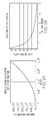
- Figures 2A and 2B are charts illustrating Mode Field Radius and Solid Core Fiber SBS Threshold
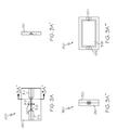
- Figures 3A , 3B , 3C, 3D and 3E illustrate a Fiber Alignment Bench of one embodiment of the present invention
- Figure 4 illustrates a resonant fiber optic gyroscope of one embodiment of the present invention.
- Figure 5 illustrates a method of one embodiment of the present invention.
- Embodiments of the present invention provide for a hollow core fiber resonant cavity wherein the mirrored portions of the cavity are decoupled from the fiber forming the resonant cavity. Instead, reflective surfaces (i.e. mirrors having desired transmission and reflection characteristics) are placed on the input and output fiber tips of solid core fibers that feed and reflect light into a length of hollow core fiber. This allows hollow core fiber, which will not accept a mirrored coating, to be used to form a fiber resonant cavity. Assembly requires alignment of only four optical elements, the fiber tips, each with only one degree of freedom, ⁇ z .
- Embodiments of the present invention further provide for a silicon fiber alignment bench for optically coupling and aligning the mirrored solid core fibers with the hollow core fiber.
- Figure 1 is a diagram illustrating generally at 100 a hollow core fiber resonant cavity apparatus of one embodiment of the present invention.
- the hollow core fiber resonant cavity 100 comprises a hollow core fiber 110 of length l and having an input end 120 and output end 122.
- hollow core fiber 110 is coiled around a PZT 115.
- Hollow core fiber resonant cavity 100 further comprises an first pigtail fiber 130 and a second pigtail fiber 132 both comprising lengths of solid core fiber material.
- input fiber 130 and output fiber 132 are both lengths of polarization maintaining (PM) fiber.
- PM polarization maintaining
- the solid core fiber tips (shown at 131 and 133) of input fiber 130 and output fiber 132 are aligned adjacent to the input end 120 and output end 122 of hollow core fiber 110, respectively. Faces of fiber tips 131 and 133 are each coated with a low transmission coating (shown at 140 and 142). That is, coatings 140 and 142 effectively function as mirrors. With this configuration, hollow core fiber 110, together with the coated solid core fiber tips 131 and 133, forms a resonant cavity from the hollow core fiber 110 between high reflection coatings on the input and output tips of the solid core pigtail fibers 130 and 131.
- light 170 enters the hollow core fiber resonant cavity 100 from the first pigtail fiber 130 and passes through low transmission coating 140 into hollow core fiber 110.
- low transmission coating 142 only a small percentage of the received light exits through the second pigtail fiber 132.
- the balance of the light is reflected back into hollow core fiber 110 by low transmission coating 142. Once that reflected light reaches low transmission coating 140, only a small percentage of the light is transmitted back to the first pigtail fiber 130.
- the balance of the light is again reflected back into the first end 120 of hollow core fiber 110 in addition to the light 170 still entering from the light source.
- the resonant cavity thus functions from coatings 140 and 142 repeatedly reflecting, and then re-reflecting light, between ends 120 and 122 of hollow core fiber 110.
- light may enter the cavity 100 from either pigtail fiber 130 or 132 to form a resonant cavity filter.
- light may enter cavity 100 from both pigtail fiber 130 and 132 at the same time thus forming two independent resonant filter cavities.
- Considerations for selecting materials to create the low transmission coatings 140 and 142 include the length of hollow core fiber 110 and its refractive index and the desired transmission of the hollow core fiber resonant cavity 100 as a whole for a particular bandwidth of light that is to be resonant in the cavity 100.
- the solid core fiber tips 131 and 133 are each positioned a distance ⁇ from the respective ends 120 and 122 of hollow core fiber 110.
- the distance ⁇ places the tips 131 and 133 within the Rayleigh range of the hollow core fiber ends 120 and 133 for efficient coupling of light into the hollow core fiber cavity 110.
- the separation between the fibers is ⁇ ⁇ 0.
- the coatings 140, 142 may be applied to short segments of PM fiber to form pigtail fibers 130 and 132, which are then attached to leads of other devices (such as a light source or optical detector leads) with a low loss splice as there is a negligible performance penalty for splices outside of the fiber resonant cavity 100.
- Implementation of resonant cavity 100 benefits from stable self centering mechanical fixtures for mechanical alignment between solid core fiber tips 131 and 133 and hollow core fiber ends 120 and 122.
- One such structure is a V-groove etched in silicon. Silicon V-grooves provide adequate alignment for like diameter solid and hollow core fibers. Accommodation of dissimilar diameter fibers are made with juxtaposed dissimilar V-grooves. That is, core-to-core alignment of dissimilar diameter fibers can be accomplished by modifying V-groove widths. In the embodiment shown in Figure 1 , this alignment is achieved at each end of hollow core fiber 110 by a fiber alignment bench 150.
- Figures 3A , 3B , 3C, 3D and 3F are diagrams illustrating a fiber alignment bench 300 constructed from an etched silicon crystal substrate 310 for use as a fiber alignment bench 150 for resonant cavity 100.
- the large V-grooves 312 and 314 etched into substrate 310 accommodates the jacketed fibers while the smaller V-grooves 316 and 318 joining the larger V-grooves 312 and 314 accommodate the two fibers cores to be coupled-the hollow core fiber and the solid core fiber, with jackets stripped off.
- the fibers are held in place using an adhesive applied as a liquid which hardens to fix the fibers in their respective V-grooves with cores aligned and a distance apart (i.e., ⁇ as shown in Figure 1 ) within the Rayleigh range.
- the jacketed first pigtail fiber 130 would be placed within V-groove 312 with the stripped and coated solid core fiber tip 131 placed within V-groove 316.
- a portion of the jacketed hollow core fiber 110 would be placed in V-groove 314 with the stripped end 120 positioned within V-groove 318.
- Solid core fiber tip 131 and stripped end 120 could then be precision aligned (using a microscope for example) to be a distance ⁇ from each other within the Rayleigh range. An adhesive is then applied to each fiber so that alignment is maintained.
- the fiber alignment bench 300 further comprises a cross-cut V-grove 320 which traverses across V-grooves 316 and 318 where solid core fiber tip 131 and stripped end 120 meet.
- a cross-cut V-grove 320 which traverses across V-grooves 316 and 318 where solid core fiber tip 131 and stripped end 120 meet.
- the etched cross-cut V-grove 320 at this position within silicon crystal substrate 310 will remove support, leaving fiber tip 131 and stripped end 120 cantilevered at the coupling point. This defeats adhesive wicking to cover, or partially cover the fiber tips during fabrication. That is, cross-cut V-grove 320 disrupts capillary action from pulling the adhesive applied to solid core fiber tip 131 and stripped end 120 into gap 125.
- solid core fiber tip 133 and end 122 would be coupled together in the exact same manner as described above using a second implementation of a fiber alignment bench 300.
- fiber alignment bench 300 has been described above in conjunction with forming a hollow core fiber resonant cavity by coupling solid and hollow core fiber, one of ordinary skill in the art who has studied this disclosure would appreciate that in other embodiments, fiber alignment bench 300 would be useful to couple together two solid core fiber filters, or two hollow core fiber filter, as well.
- Figure 4 illustrates a diagram of one embodiment of the present invention of a resonant fiber optic gyroscope 400 which comprises two implementations of a hollow core fiber resonant cavity 100 such as described above in Figure 1 . These are shown in Figure 4 as hollow core fiber resonant filter 410 and hollow core fiber resonant filter 420.
- Figure 4 is a simplified diagram of a resonant fiber optic gyroscope for the purposes of showing how a hollow core fiber resonant cavity could be integrated into such a device.
- other components such as intensity modulators, which would be known to those of ordinary skill in the art, are omitted from this diagram for simplicity.
- a first laser source 402 feeds light into the first hollow core fiber resonant filter 410, which forms a resonant cavity as described above.
- the light from first laser source 402 then proceeds through a first circulator 412 and into a rotation rate sensing loop 430 via a coupler 414.
- This light traverses the rotation rate sensing loop 430 and exits through a second circulator 422 into a photo-detector 426 designated as the "clockwise photo-detector", from which the time varying intensity fluctuations are measured and reduced to a rotation rate.
- a second laser source 404 feeds light into the second hollow core fiber resonant filter 420, which also forms a resonant cavity as described above.
- the light from second laser source 404 then proceeds through the second circulator 422 and into the rotation rate sensing loop 430 via a coupler 424.
- This light traverses the rotation rate sensing loop 430 and exits through the first circulator 412 into a photo-detector 416 designated as the "counterclockwise photo-detector", from which the time varying intensity fluctuations are also measured and reduced to a rotation rate.
- hollow core fiber resonant filter 410 and 420 each function to eliminate phase noise in the light from the respective lasers. Further, because hollow core fiber Resonant filter 410 and 420 utilize hollow cores rather that solid cores, the optical signal intensity of the outputs of laser sources 402 and 404 can be set higher than those for prior art resonant fiber optic gyroscope that utilize solid core resonant filter without producing parasitic effects as light intensity increases. As such, inclusion of hollow core fiber resonant filters 410 and 420 serve to increase the accuracy of rotation rate measurements from resonant fiber optic gyroscope 400.
- Figure 5 is a method of one embodiment of the present invention for a hollow core resonant filter.
- the method begins at 500 with transmitting a light beam through a first solid core fiber.
- the method proceeds to 510 with optically coupling the light beam from an end of the first solid core fiber to a first end of a hollow core fiber across a first free-space gap.
- the end of the first solid core fiber is coated to reflect the light beam as received from the first end of the hollow core fiber back across the first free-space gap into the first end of the hollow core fiber.
- the method proceeds to 520 with optically coupling the light beam from a second end of the hollow core fiber to an end of a second solid core fiber across a second free-space gap.
- the end of the second solid core fiber is coated to reflect the light beam as received from the second end of the hollow core fiber back across the second free-space gap into the second end of the hollow core fiber.
- the solid core fiber tips of the solid core fibers are aligned adjacent to the first and second ends of the hollow core fiber, respectively. Faces of fiber tips 131 and 133 are each coated with a low transmission coating (shown at 140 and 142). Coatings applied to the faces of the solid core fiber tips effectively function as mirrors to reflect light back in to the hollow core fiber.
- the hollow core fiber together with the coated solid core fiber tips forms a resonant cavity from the hollow core fiber between high reflection coatings on the input and output tips of the solid core pigtail fibers.
- light from a light source such as a laser diode for example
- the resonant cavity thus functions from the high reflective, low transmission coatings on the tips of the solid core fibers repeatedly reflecting, and then re-reflecting light, between the two ends the hollow core fiber.
- the first and second free-space gaps provide a distance between the solid and hollow core fibers that is less that the Rayleigh range. Further in one embodiment, alignment of the solid and hollow core fibers is achieved through a fiber alignment bench such as described above with respect to Figure 1 and 3A-B .
- Example 1 includes A method for a hollow core resonant filter, the method comprising transmitting a light beam through a first solid core fiber; optically coupling the light beam from an end of the first solid core fiber to a first end of a hollow core fiber across a first free-space gap; optically coupling the light beam from a second end of the hollow core fiber to an end of a second solid core fiber across a second free-space gap; wherein the end of the second solid core fiber is coated to reflect the light beam as received from the second end of the hollow core fiber back across the second free-space gap into the second end of the hollow core fiber; and wherein the end of the first solid core fiber is coated to reflect the light beam as received from the first end of the hollow core fiber back across the first free-space gap into the first end of the hollow core fiber.
- Example 2 includes the method of Example 1, wherein the end of the first solid core fiber and the first end of the hollow core fiber are separated by the first free-space gap by a distance, ⁇ , that is less that the Rayleigh range.
- Example 3 includes the method of any of Examples 1-2, wherein the end of the second solid core fiber and the second end of the hollow core fiber are separated by the second free-space gap by a distance, ⁇ , that is less that the Rayleigh range.
- Example 4 includes the method of any of Examples 1-3, further comprising, aligning the first solid core fiber and the first end of the hollow core fiber by securing the first solid core fiber within a first V-groove of a fiber alignment bench and securing the first end of the hollow core fiber within a second V-groove of the fiber alignment bench; wherein the fiber alignment bench is formed from a silicon crystal material.
- Example 5 includes the method of Example 4, wherein the fiber alignment bench includes a cross-cut V-groove at a coupling point between the first solid core fiber and the first end of the hollow core fiber that removes support such that a portion of the first solid core fiber and a portion of the end of the hollow core fiber are cantilevered at the coupling point.
- Example 6 includes a hollow core fiber resonant cavity, the resonant cavity comprising a hollow core fiber having a first end and a second end; a first pigtail fiber of solid core fiber material; a second pigtail fiber of solid core fiber material; wherein a fiber tip of the first pigtail fiber is optically aligned with the first end of the hollow core fiber to couple light from the first pigtail fiber to the hollow core fiber across a first free-space gap; wherein a fiber tip of the second pigtail fiber is optically aligned with the second end of the hollow core fiber to couple light from the second pigtail fiber to the hollow core fiber across a second free-space gap; wherein the fiber tip of the second pigtail fiber is coated to reflect light received from the second end of the hollow core fiber back across the second free-space gap into the second end of the hollow core fiber; and wherein the fiber tip of the first pigtail fiber is coated to reflect light received from the first end of the hollow core fiber back across the first free-space gap into the first end of
- Example 7 includes the resonant cavity of Example 6, wherein one or both of the first pigtail fiber and the second pigtail fiber include lengths of polarization maintaining fiber.
- Example 8 includes the resonant cavity of any of Examples 6-7, further comprising a first fiber alignment bench of silicon material securing the fiber tip of the first pigtail fiber within a first V-groove and the first end of the hollow core fiber within a second V-groove.
- Example 9 includes the resonant cavity of Example 8, the first fiber alignment bench further comprising a cross-cut V-groove at a coupling point between the fiber tip of the first pigtail fiber and the first end of the hollow core fiber such that a portion of the first solid core fiber and a portion of the end of the hollow core fiber are cantilevered at the coupling point.
- Example 10 includes the resonant cavity of any of Examples 6-9, wherein the fiber tip of the first pigtail fiber and the first end of the hollow core fiber are separated by the first free-space gap by a distance, ⁇ , that is less that the Rayleigh range.
- Example 11 includes the resonant cavity of any of Examples 6-10, wherein the fiber tip of the second pigtail fiber and the second end of the hollow core fiber are separated by the second free-space gap by a distance, ⁇ , that is less that the Rayleigh range.
- Example 12 includes the resonant cavity of any of Examples 6-11, wherein a first coating applied to the fiber tip of the first pigtail fiber and a second coating applied to the fiber tip of the second pigtail fiber each have transmission and reflection properties such that a bandwidth of light entering the first pigtail will resonate within the hollow core fiber.
- Example 13 includes a resonant fiber optic gyroscope, the gyroscope comprising a first laser source; a first hollow core fiber resonant cavity filter having an input end and an output end, wherein the first end of the first hollow core fiber resonant cavity filter is coupled to the first laser source; a rotation rate sensing loop having a first end and a second end; a first circulator coupled to the output end of the first hollow core fiber resonant cavity filter, a first photo-detector, and the first end of the rotation rate sensing loop, wherein the first circulator passes light received from the first hollow core fiber resonant cavity filter to the first end of rotation rate sensing loop, and light received from the first end of the rotation rate sensing loop to the first photo-detector; a second laser source; a second hollow core fiber resonant cavity filter having an input end and an output end, wherein the first end of the second hollow core fiber resonant cavity filter is an input coupled to the second laser source; a
- Example 14 includes the gyroscope of Example 13, wherein one or both of the first pigtail fiber and the second pigtail fiber include lengths of polarization maintaining fiber.
- Example 15 includes the gyroscope of any of Examples 13-14, wherein the first hollow core fiber resonant cavity filter and the second hollow core fiber resonant cavity filter each further comprise a first fiber alignment bench of silicon material securing the fiber tip of the first pigtail fiber within a first V-groove and the first end of the hollow core fiber within a second V-groove; and a second fiber alignment bench of silicon material securing the fiber tip of the second pigtail fiber within a third V-groove and the second end of the hollow core fiber within a fourth V-groove.
- the first hollow core fiber resonant cavity filter and the second hollow core fiber resonant cavity filter each further comprise a first fiber alignment bench of silicon material securing the fiber tip of the first pigtail fiber within a first V-groove and the first end of the hollow core fiber within a second V-groove; and a second fiber alignment bench of silicon material securing the fiber tip of the second pigtail fiber within a third V-gro
- Example 16 includes the gyroscope of Example 15, the first fiber alignment bench and second fiber alignment bench each further comprising a cross-cut V-groove.
- Example 17 includes the gyroscope of any of Examples 13-16, wherein the fiber tip of the first pigtail fiber and the first end of the hollow core fiber are separated by the first free-space gap by a distance, ⁇ , that is less that the Rayleigh range.
- Example 18 includes the gyroscope of any of Examples 13-17, wherein the fiber tip of the second pigtail fiber and the second end of the hollow core fiber are separated by the second free-space gap by a distance, ⁇ , that is less that the Rayleigh range.
- Example 19 includes the gyroscope of any of Examples 13-18, wherein a first coating applied to the fiber tip of the first pigtail fiber and a second coating applied to the fiber tip of the second pigtail fiber each have transmission and reflection properties such that a bandwidth of light entering the first pigtail will resonate within the hollow core fiber.
- Example 20 includes the gyroscope of any of Examples 13-20, wherein the first photo-detector measures time varying intensity fluctuations for light travelling counterclockwise through the rotation rate sensing loop and the second photo-detector measures time varying intensity fluctuation for light travelling clock-wise through the rotation rate sensing loop.
Landscapes
- Physics & Mathematics (AREA)
- Engineering & Computer Science (AREA)
- General Physics & Mathematics (AREA)
- Optics & Photonics (AREA)
- Electromagnetism (AREA)
- Power Engineering (AREA)
- Radar, Positioning & Navigation (AREA)
- Remote Sensing (AREA)
- Optical Couplings Of Light Guides (AREA)
- Gyroscopes (AREA)
Applications Claiming Priority (1)
| Application Number | Priority Date | Filing Date | Title |
|---|---|---|---|
| US13/239,145 US20130070252A1 (en) | 2011-09-21 | 2011-09-21 | Systems and methods for a hollow core resonant filter |
Publications (1)
| Publication Number | Publication Date |
|---|---|
| EP2573600A1 true EP2573600A1 (fr) | 2013-03-27 |
Family
ID=46754254
Family Applications (1)
| Application Number | Title | Priority Date | Filing Date |
|---|---|---|---|
| EP12175476A Withdrawn EP2573600A1 (fr) | 2011-09-21 | 2012-07-09 | Systèmes et procédés pour filtre de résonance avec un coeur de fibre optique creux |
Country Status (3)
| Country | Link |
|---|---|
| US (1) | US20130070252A1 (fr) |
| EP (1) | EP2573600A1 (fr) |
| JP (1) | JP2013068604A (fr) |
Cited By (2)
| Publication number | Priority date | Publication date | Assignee | Title |
|---|---|---|---|---|
| EP2927636A1 (fr) * | 2014-04-02 | 2015-10-07 | Honeywell International Inc. | Systèmes et procédés pour lasers à diffusion stimulée de brillouin stabilisés à très faible bruit de phase |
| EP3421934A1 (fr) * | 2017-06-28 | 2019-01-02 | Honeywell International Inc. | Gyroscope à fibre optique résonant comportant des fibres à c ur creux |
Families Citing this family (35)
| Publication number | Priority date | Publication date | Assignee | Title |
|---|---|---|---|---|
| US9541610B2 (en) | 2015-02-04 | 2017-01-10 | Lockheed Martin Corporation | Apparatus and method for recovery of three dimensional magnetic field from a magnetic detection system |
| US9590601B2 (en) | 2014-04-07 | 2017-03-07 | Lockheed Martin Corporation | Energy efficient controlled magnetic field generator circuit |
| US9910105B2 (en) | 2014-03-20 | 2018-03-06 | Lockheed Martin Corporation | DNV magnetic field detector |
| US9557391B2 (en) | 2015-01-23 | 2017-01-31 | Lockheed Martin Corporation | Apparatus and method for high sensitivity magnetometry measurement and signal processing in a magnetic detection system |
| CN104931035B (zh) * | 2015-06-19 | 2018-02-09 | 浙江大学 | 一种基于空芯带隙光纤的反射式环形谐振腔及应用 |
| WO2017095454A1 (fr) | 2015-12-01 | 2017-06-08 | Lockheed Martin Corporation | Communication par le biais d'un magnétomètre |
| WO2017127079A1 (fr) | 2016-01-21 | 2017-07-27 | Lockheed Martin Corporation | Détection d'anomalies magnétiques de vecteur ca avec des centres azote-lacune du diamant |
| WO2017127096A1 (fr) | 2016-01-21 | 2017-07-27 | Lockheed Martin Corporation | Capteur d'azote-lacune de diamant avec doubles sources rf |
| US10571530B2 (en) | 2016-05-31 | 2020-02-25 | Lockheed Martin Corporation | Buoy array of magnetometers |
| US10345396B2 (en) | 2016-05-31 | 2019-07-09 | Lockheed Martin Corporation | Selected volume continuous illumination magnetometer |
| US10359479B2 (en) | 2017-02-20 | 2019-07-23 | Lockheed Martin Corporation | Efficient thermal drift compensation in DNV vector magnetometry |
| US10527746B2 (en) | 2016-05-31 | 2020-01-07 | Lockheed Martin Corporation | Array of UAVS with magnetometers |
| US10371765B2 (en) | 2016-07-11 | 2019-08-06 | Lockheed Martin Corporation | Geolocation of magnetic sources using vector magnetometer sensors |
| US10281550B2 (en) | 2016-11-14 | 2019-05-07 | Lockheed Martin Corporation | Spin relaxometry based molecular sequencing |
| US10677953B2 (en) | 2016-05-31 | 2020-06-09 | Lockheed Martin Corporation | Magneto-optical detecting apparatus and methods |
| US10338163B2 (en) | 2016-07-11 | 2019-07-02 | Lockheed Martin Corporation | Multi-frequency excitation schemes for high sensitivity magnetometry measurement with drift error compensation |
| US10274550B2 (en) | 2017-03-24 | 2019-04-30 | Lockheed Martin Corporation | High speed sequential cancellation for pulsed mode |
| US10317279B2 (en) | 2016-05-31 | 2019-06-11 | Lockheed Martin Corporation | Optical filtration system for diamond material with nitrogen vacancy centers |
| US10345395B2 (en) | 2016-12-12 | 2019-07-09 | Lockheed Martin Corporation | Vector magnetometry localization of subsurface liquids |
| US10408890B2 (en) | 2017-03-24 | 2019-09-10 | Lockheed Martin Corporation | Pulsed RF methods for optimization of CW measurements |
| US10330744B2 (en) | 2017-03-24 | 2019-06-25 | Lockheed Martin Corporation | Magnetometer with a waveguide |
| US10338164B2 (en) | 2017-03-24 | 2019-07-02 | Lockheed Martin Corporation | Vacancy center material with highly efficient RF excitation |
| US10459041B2 (en) | 2017-03-24 | 2019-10-29 | Lockheed Martin Corporation | Magnetic detection system with highly integrated diamond nitrogen vacancy sensor |
| US10379174B2 (en) | 2017-03-24 | 2019-08-13 | Lockheed Martin Corporation | Bias magnet array for magnetometer |
| US10371760B2 (en) | 2017-03-24 | 2019-08-06 | Lockheed Martin Corporation | Standing-wave radio frequency exciter |
| WO2019014279A2 (fr) * | 2017-07-11 | 2019-01-17 | Lockheed Martin Corporation | Appareil de type magnétomètre |
| US10451421B2 (en) | 2018-01-05 | 2019-10-22 | Honeywell International Inc. | Resonant fiber optical gyroscope using antiresonant nodeless fiber |
| GB201812744D0 (en) | 2018-08-06 | 2018-09-19 | Univ Southampton | Iterferometric optical fibre sensors |
| DK3754389T3 (da) * | 2019-06-21 | 2025-09-08 | Asml Netherlands Bv | Monteret hulkernefiberindretning |
| EP3767347A1 (fr) * | 2019-07-17 | 2021-01-20 | ASML Netherlands B.V. | Agencement monté de fibres à noyau creux |
| CN112670809B (zh) * | 2020-12-11 | 2023-08-11 | 华南师范大学 | 一种阳光泵浦气体光纤激光器 |
| CN112670808A (zh) * | 2020-12-11 | 2021-04-16 | 华南师范大学 | 一种阳光泵浦光纤激光器 |
| CN114166201B (zh) * | 2021-11-26 | 2023-03-14 | 中国航空工业集团公司西安飞行自动控制研究所 | 一种集成化偏振抑制光纤谐振腔 |
| US12066655B2 (en) * | 2021-12-14 | 2024-08-20 | Optoskand Ab | Terminated hollow-core fiber with endcap |
| CN119085619B (zh) * | 2024-08-30 | 2025-09-26 | 中国船舶集团有限公司第七〇七研究所 | 一种空芯光子晶体光纤环圈尾纤盘绕实施系统及盘绕方法 |
Citations (3)
| Publication number | Priority date | Publication date | Assignee | Title |
|---|---|---|---|---|
| DE3929453C1 (en) * | 1989-09-05 | 1991-03-21 | Messerschmitt-Boelkow-Blohm Gmbh, 8012 Ottobrunn, De | Fibre-Fabry-Perot interferometer - has slot in substrate enabling opposite regions to be moved w.r.t. V=shaped groove for optical fibres |
| US20020085810A1 (en) * | 2000-12-30 | 2002-07-04 | Myung-Hyun Lee | Tunable fabry-perot filter and method for fabricating the same |
| CN101387608A (zh) * | 2008-05-27 | 2009-03-18 | 重庆大学 | 超长珐-珀干涉式气体传感器及基于传感器的气体测试仪 |
Family Cites Families (25)
| Publication number | Priority date | Publication date | Assignee | Title |
|---|---|---|---|---|
| US4372768A (en) * | 1981-04-27 | 1983-02-08 | Gte Automatic Electric Laboratories, Inc. | Method of splicing ends of optical fibers |
| GB8611361D0 (en) * | 1986-05-09 | 1986-06-18 | Bicc Plc | Splicing optical fibre ribbon |
| DE59010576D1 (de) * | 1989-06-02 | 1997-01-09 | Siemens Ag | Verfahren zur Ausrichtung zweier Lichtwellenleiter-Faserenden und Einrichtung zur Durchführung des Verfahrens |
| US5285516A (en) * | 1992-03-18 | 1994-02-08 | Kaptron, Inc. | Fused fiber optic attenuator having axially overlapping fiber end portions |
| US5517303A (en) * | 1993-03-08 | 1996-05-14 | Dylor Corporation | Coherence selective sensor system |
| US5978125A (en) * | 1995-11-30 | 1999-11-02 | Yao; X. Steve | Compact programmable photonic variable delay devices |
| JP3065271B2 (ja) * | 1997-04-10 | 2000-07-17 | 住友電気工業株式会社 | 融着接続装置 |
| DE19737358A1 (de) * | 1997-08-27 | 1999-03-04 | Siemens Ag | Verfahren sowie Vorrichtung zum thermischen Verschweißen von Lichtleitfasern |
| US6545261B1 (en) * | 1999-08-31 | 2003-04-08 | James N. Blake | Fiber optic alignment system and method |
| US6424762B1 (en) * | 2000-03-07 | 2002-07-23 | Institut National D'optique | Superfluorescent fiber source |
| EP1174744A1 (fr) * | 2000-07-21 | 2002-01-23 | Corning Incorporated | Méthode et dispositif pour épisser des fibres optiques |
| GB2365992B (en) * | 2000-08-14 | 2002-09-11 | Univ Southampton | Compound glass optical fibres |
| US6731423B1 (en) * | 2001-08-15 | 2004-05-04 | Neumann Information Systems Inc | Optical amplifier and method |
| US7062135B2 (en) * | 2002-03-21 | 2006-06-13 | Corning Incorporated | Method for fabricating curved elements |
| US20040071414A1 (en) * | 2002-10-15 | 2004-04-15 | Fitel Interconnectivity Corp. | System, controller and method for fusion splicing at least one pair of optical fibers |
| GB0327661D0 (en) * | 2003-11-28 | 2003-12-31 | Qinetiq Ltd | Optical Amplifier |
| US20050201715A1 (en) * | 2004-03-29 | 2005-09-15 | Panorama Flat Ltd. | System, method, and computer program product for magneto-optic device display |
| US7280567B2 (en) * | 2004-03-12 | 2007-10-09 | Pavilion Integration Corporation | High-power red, orange, green, blue (ROGB) fiber lasers and applications thereof |
| US7430345B2 (en) * | 2006-03-02 | 2008-09-30 | The Board Of Trustees Of The Leland Stanford Junior University | Polarization controller using a hollow-core photonic-bandgap fiber |
| US20090041062A1 (en) * | 2007-04-11 | 2009-02-12 | Jian Liu | Fiber-based tunable laser |
| EP2286290A4 (fr) * | 2008-05-09 | 2015-04-01 | Hewlett Packard Development Co | Procédés de fabrication de guides d'ondes creux à c ur de grande dimension |
| US7680372B2 (en) * | 2008-06-27 | 2010-03-16 | Honeywell International Inc. | Micro-optics photonic bandgap fiber coupler |
| US8229304B1 (en) * | 2009-04-30 | 2012-07-24 | Hrl Laboratories, Llc | Phase control of a fiber optic bundle |
| WO2011060097A2 (fr) * | 2009-11-10 | 2011-05-19 | California Institute Of Technology | Tomographie optique à conjugué de phase assistée par acoustique |
| CN102073104B (zh) * | 2011-03-01 | 2012-07-04 | 重庆大学 | 基于空芯光子带隙光纤和微光纤的可调谐f-p滤波器 |
-
2011
- 2011-09-21 US US13/239,145 patent/US20130070252A1/en not_active Abandoned
-
2012
- 2012-07-09 EP EP12175476A patent/EP2573600A1/fr not_active Withdrawn
- 2012-07-18 JP JP2012159272A patent/JP2013068604A/ja active Pending
Patent Citations (3)
| Publication number | Priority date | Publication date | Assignee | Title |
|---|---|---|---|---|
| DE3929453C1 (en) * | 1989-09-05 | 1991-03-21 | Messerschmitt-Boelkow-Blohm Gmbh, 8012 Ottobrunn, De | Fibre-Fabry-Perot interferometer - has slot in substrate enabling opposite regions to be moved w.r.t. V=shaped groove for optical fibres |
| US20020085810A1 (en) * | 2000-12-30 | 2002-07-04 | Myung-Hyun Lee | Tunable fabry-perot filter and method for fabricating the same |
| CN101387608A (zh) * | 2008-05-27 | 2009-03-18 | 重庆大学 | 超长珐-珀干涉式气体传感器及基于传感器的气体测试仪 |
Non-Patent Citations (2)
| Title |
|---|
| DATABASE WPI Week 200925, Derwent World Patents Index; AN 2009-G98847, XP002688910 * |
| MARTY P T ET AL: "All-Fiber Multi-Purpose Gas Cells and Their Applications in Spectroscopy", JOURNAL OF LIGHTWAVE TECHNOLOGY, IEEE SERVICE CENTER, NEW YORK, NY, US, vol. 28, no. 8, 15 April 2010 (2010-04-15), pages 1236 - 1240, XP011304087, ISSN: 0733-8724 * |
Cited By (4)
| Publication number | Priority date | Publication date | Assignee | Title |
|---|---|---|---|---|
| EP2927636A1 (fr) * | 2014-04-02 | 2015-10-07 | Honeywell International Inc. | Systèmes et procédés pour lasers à diffusion stimulée de brillouin stabilisés à très faible bruit de phase |
| US9197032B2 (en) | 2014-04-02 | 2015-11-24 | Honeywell International Inc. | Systems and methods for stabilized stimulated brillouin scattering lasers with ultra-low phase noise |
| EP3421934A1 (fr) * | 2017-06-28 | 2019-01-02 | Honeywell International Inc. | Gyroscope à fibre optique résonant comportant des fibres à c ur creux |
| US10598492B2 (en) | 2017-06-28 | 2020-03-24 | Honeywell International Inc. | Resonant fiber optic gyroscope with hollow core fiber |
Also Published As
| Publication number | Publication date |
|---|---|
| US20130070252A1 (en) | 2013-03-21 |
| JP2013068604A (ja) | 2013-04-18 |
Similar Documents
| Publication | Publication Date | Title |
|---|---|---|
| US20130070252A1 (en) | Systems and methods for a hollow core resonant filter | |
| JP3497298B2 (ja) | 光ファイバフィルタ | |
| EP3479443B1 (fr) | Résonateur optique, procédé de fabrication du résonateur optique et ses applications | |
| US20040086228A1 (en) | Fiber optic fabry-perot interferometer and associated methods | |
| CA2964493A1 (fr) | Ensemble fibre optique ayant un element de formation de faisceau | |
| JP5590794B2 (ja) | ファイバーを基礎にした共振器結合のためのシステムおよび方法 | |
| EP0233896A1 (fr) | Dispositif de guide d'onde optique dielectrique. | |
| US7702189B2 (en) | Fiber optic chemical sensor | |
| US11977254B2 (en) | Composed multicore optical fiber device | |
| Sabert et al. | Versatile acoustooptical flexural wave modulator, filter and frequency shifter in dual-core fibre | |
| Fsaifes et al. | A test resonator for Kagome hollow-core photonic crystal fibers for resonant rotation sensing | |
| JP5669937B2 (ja) | マルチモード干渉計技術 | |
| Imai et al. | Speckle-pattern contrast of semiconductor laser propagating in a multimode optical fiber | |
| RU2720264C1 (ru) | Перестраиваемый волоконный отражательный интерферометр | |
| US20260088582A1 (en) | Optical devices including mode field adapters having coreless and graded index optical fibers | |
| CN104931035A (zh) | 一种基于空芯带隙光纤的反射式环形谐振腔及应用 | |
| Algorri et al. | Microfluidic sensor based on a microbubble-phase-shifted fibre Bragg grating | |
| Bai et al. | A fiber etched cavity for microsphere whispering-gallery-mode excitation | |
| Yang et al. | Fano resonance in reflective fiber coupled microsphere resonators | |
| Eom et al. | Novel optical fiber connector using long-period fiber gratings | |
| Saktioto et al. | Effects of unstable torch flame for a fused single mode fiber | |
| Pal et al. | A Course in Optical Waveguides | |
| Fang et al. | Absorption spectra of fiber in UV band, 187 Acoustic frequency phonon, 282 Acoustic optical modulator (AOM), 294 | |
| Lin et al. | Fiber-optic micro-bending sensor using the multimode interference | |
| Belansky | Curvature effects in single mode and multimode optical fibers and fiber Bragg gratings |
Legal Events
| Date | Code | Title | Description |
|---|---|---|---|
| PUAI | Public reference made under article 153(3) epc to a published international application that has entered the european phase |
Free format text: ORIGINAL CODE: 0009012 |
|
| 17P | Request for examination filed |
Effective date: 20120709 |
|
| AK | Designated contracting states |
Kind code of ref document: A1 Designated state(s): AL AT BE BG CH CY CZ DE DK EE ES FI FR GB GR HR HU IE IS IT LI LT LU LV MC MK MT NL NO PL PT RO RS SE SI SK SM TR |
|
| AX | Request for extension of the european patent |
Extension state: BA ME |
|
| STAA | Information on the status of an ep patent application or granted ep patent |
Free format text: STATUS: THE APPLICATION IS DEEMED TO BE WITHDRAWN |
|
| 18D | Application deemed to be withdrawn |
Effective date: 20150203 |