EP2573636A2 - Logique de commutation de contrôle à canaux multiples - Google Patents
Logique de commutation de contrôle à canaux multiples Download PDFInfo
- Publication number
- EP2573636A2 EP2573636A2 EP12183922A EP12183922A EP2573636A2 EP 2573636 A2 EP2573636 A2 EP 2573636A2 EP 12183922 A EP12183922 A EP 12183922A EP 12183922 A EP12183922 A EP 12183922A EP 2573636 A2 EP2573636 A2 EP 2573636A2
- Authority
- EP
- European Patent Office
- Prior art keywords
- control
- microprocessor
- control microprocessor
- primary
- primary control
- Prior art date
- Legal status (The legal status is an assumption and is not a legal conclusion. Google has not performed a legal analysis and makes no representation as to the accuracy of the status listed.)
- Granted
Links
Images


Classifications
-
- G—PHYSICS
- G05—CONTROLLING; REGULATING
- G05B—CONTROL OR REGULATING SYSTEMS IN GENERAL; FUNCTIONAL ELEMENTS OF SUCH SYSTEMS; MONITORING OR TESTING ARRANGEMENTS FOR SUCH SYSTEMS OR ELEMENTS
- G05B19/00—Program-control systems
- G05B19/02—Program-control systems electric
- G05B19/04—Program control other than numerical control, i.e. in sequence controllers or logic controllers
- G05B19/042—Program control other than numerical control, i.e. in sequence controllers or logic controllers using digital processors
- G05B19/0421—Multiprocessor system
-
- G—PHYSICS
- G05—CONTROLLING; REGULATING
- G05B—CONTROL OR REGULATING SYSTEMS IN GENERAL; FUNCTIONAL ELEMENTS OF SUCH SYSTEMS; MONITORING OR TESTING ARRANGEMENTS FOR SUCH SYSTEMS OR ELEMENTS
- G05B19/00—Program-control systems
- G05B19/02—Program-control systems electric
- G05B19/04—Program control other than numerical control, i.e. in sequence controllers or logic controllers
- G05B19/042—Program control other than numerical control, i.e. in sequence controllers or logic controllers using digital processors
- G05B19/0428—Safety, monitoring
-
- G—PHYSICS
- G06—COMPUTING OR CALCULATING; COUNTING
- G06F—ELECTRIC DIGITAL DATA PROCESSING
- G06F11/00—Error detection; Error correction; Monitoring
- G06F11/07—Responding to the occurrence of a fault, e.g. fault tolerance
- G06F11/16—Error detection or correction of the data by redundancy in hardware
- G06F11/20—Error detection or correction of the data by redundancy in hardware using active fault-masking, e.g. by switching out faulty elements or by switching in spare elements
- G06F11/202—Error detection or correction of the data by redundancy in hardware using active fault-masking, e.g. by switching out faulty elements or by switching in spare elements where processing functionality is redundant
- G06F11/2023—Failover techniques
- G06F11/2033—Failover techniques switching over of hardware resources
-
- G—PHYSICS
- G06—COMPUTING OR CALCULATING; COUNTING
- G06F—ELECTRIC DIGITAL DATA PROCESSING
- G06F11/00—Error detection; Error correction; Monitoring
- G06F11/07—Responding to the occurrence of a fault, e.g. fault tolerance
- G06F11/16—Error detection or correction of the data by redundancy in hardware
- G06F11/20—Error detection or correction of the data by redundancy in hardware using active fault-masking, e.g. by switching out faulty elements or by switching in spare elements
- G06F11/202—Error detection or correction of the data by redundancy in hardware using active fault-masking, e.g. by switching out faulty elements or by switching in spare elements where processing functionality is redundant
- G06F11/2041—Error detection or correction of the data by redundancy in hardware using active fault-masking, e.g. by switching out faulty elements or by switching in spare elements where processing functionality is redundant with more than one idle spare processing component
-
- G—PHYSICS
- G05—CONTROLLING; REGULATING
- G05B—CONTROL OR REGULATING SYSTEMS IN GENERAL; FUNCTIONAL ELEMENTS OF SUCH SYSTEMS; MONITORING OR TESTING ARRANGEMENTS FOR SUCH SYSTEMS OR ELEMENTS
- G05B2219/00—Program-control systems
- G05B2219/10—Plc systems
- G05B2219/14—Plc safety
- G05B2219/14014—Redundant processors and I-O
-
- G—PHYSICS
- G05—CONTROLLING; REGULATING
- G05B—CONTROL OR REGULATING SYSTEMS IN GENERAL; FUNCTIONAL ELEMENTS OF SUCH SYSTEMS; MONITORING OR TESTING ARRANGEMENTS FOR SUCH SYSTEMS OR ELEMENTS
- G05B2219/00—Program-control systems
- G05B2219/20—Pc systems
- G05B2219/24—Pc safety
- G05B2219/24177—State machine arbitrates which redundant controller is active
-
- G—PHYSICS
- G05—CONTROLLING; REGULATING
- G05B—CONTROL OR REGULATING SYSTEMS IN GENERAL; FUNCTIONAL ELEMENTS OF SUCH SYSTEMS; MONITORING OR TESTING ARRANGEMENTS FOR SUCH SYSTEMS OR ELEMENTS
- G05B2219/00—Program-control systems
- G05B2219/20—Pc systems
- G05B2219/24—Pc safety
- G05B2219/24183—If error, spare unit takes over, message to leader, confirm new configuration
-
- G—PHYSICS
- G05—CONTROLLING; REGULATING
- G05B—CONTROL OR REGULATING SYSTEMS IN GENERAL; FUNCTIONAL ELEMENTS OF SUCH SYSTEMS; MONITORING OR TESTING ARRANGEMENTS FOR SUCH SYSTEMS OR ELEMENTS
- G05B2219/00—Program-control systems
- G05B2219/20—Pc systems
- G05B2219/24—Pc safety
- G05B2219/24186—Redundant processors are synchronised
Definitions
- the present disclosure relates to electrical controllers, and more particularly to an electronic control architecture integrating multiple control channels.
- Existing electronic controls systems typically utilize multi-channel primary controllers, and a backup controller to control a device. Under normal fault-free conditions, the primary control controls the plant. The backup controller assumes control when the primary controllers experiences some threshold degree of damage or error that the primary controllers cannot recover (e.g., a channel-wide failure such as a primary control processor failure or a power supply failure).
- Disclosed is a method of electronically controlling a device having the steps of: controlling a device using a first primary control microprocessor under normal conditions, controlling the device using a second primary control microprocessor when the first primary control microprocessor is unhealthy and the second primary control microprocessor is healthy, and controlling the device using a first secondary control microprocessor or a second secondary control microprocessor when the first primary control microprocessor and the second primary control microprocessor are unhealthy.
- an electrical control configuration having at least a first primary control microprocessor and a second primary control microprocessor operable to control a device, at least a first secondary control microprocessor and a second secondary control microprocessor operable to control the device.
- Each of the first and second primary control microprocessors and the first and second secondary control microprocessors are arranged as independent control channels.
- FIG. 1 schematically illustrates a multi-channel controllers 10.
- the multi-channel controller 10 includes two primary control microprocessors A1, B1 and two backup control microprocessors A2, B2.
- Each of the primary control microprocessors A1, B1 shares a mount 12 with a corresponding local secondary control microprocessor A2, B2.
- Each of the mounts 12 is considered a control channel.
- Alternate embodiments could use four identical control microprocessors A1, B1, A2, B2 or could locate each of the four control microprocessors A1, B1, A2, B2 on separate mounts 12.
- Each of the primary control microprocessors A1, B1 is connected to the other primary control microprocessor A1, B1 via a cross-channel data communications link and a channel in-control signal 30.
- the channel in-control signal 30 informs the other primary control microprocessor A1, B1 of the operational status of the primary control microprocessor A1, B1 and the corresponding secondary control microprocessor A2, B2.
- the channel in-control signal 30 informs the other control microprocessors A1, B1, A2, B2 that the control microprocessor A1, B1 originating the in-control signal is currently controlling the controlled device 20.
- the operational status of any of the control microprocessors A1, B1, A2, B2 is referred to as the control microprocessor's health, and when the control microprocessor ceases function, the control microprocessor is referred to as being in a failure state, or unhealthy,
- Each of the primary control microprocessors A1, B1 also includes a channel health signal 42, 44 (alternately referred to as a Channel Good Remote signal) connecting the primary control microprocessor A1, B1 to remote secondary control microprocessor A2, B2, with the secondary control microprocessor B2 being remote to the primary control microprocessor A1 and the secondary control microprocessor A2 being remote to the primary control microprocessor B1.
- a local channel health signal 60 (alternately referred to as a Channel Good Local signal) connects each of the primary control microprocessors A1, B1 with the corresponding local secondary control microprocessor A2, B2 and performs the same function as the remote channel health signals 42, 44.
- Each of the two groupings of control microprocessors A1, B1, A2, B2 is connected to the controlled device 20 via a device control signal 70. It is understood that each of the signal lines 30, 42, 44, 60, 70 illustrated in Figure 1 can represent multiple physical signals connected to the control microprocessors A1, B1, A2, B2.
- FIG. 2 illustrates an exemplary control channel with control microprocessors A1 and A2 and logic block 320, and the latching Boolean gata 321 in a control input configuration 300.
- Each of the control microprocessors has a control in-control request output 330, 331 that is passed to a standard latching Boolean gate 321 in each of the channels.
- Each of the latching Boolean gates 321 generates outputs referred to as control microprocessor in-control outputs.
- the control microprocessor in-control outputs serve as inputs to an exclusive OR gate 390.
- the output of the exclusive OR gate 390 provides a general channel in-control output 333 that is passed to the other channel (not illustrated).
- Each logic block 320 has a clear latch output 334, 336 that resets latching Boolean gate 321 output to false.
- the control input configuration 300 also includes a control microprocessor in-control logic block 320 that combines a control microprocessor A1 control microprocessor in-control output 360 or a control microprocessor A2 control in-control output 361 of the current channel and a general channel in-control output 332 of the other channel (not illustrated) into a clear latch output 334, 336.
- the control circuit corresponding to secondary control microprocessor A2 further includes an OR gate 350 that includes inputs of a local channel health signal 337 indicating the health of the primary control microprocessor A1 in the local channel and a remote health signal 339 indicating the health of the primary control microprocessor B1 in the remote channel.
- the OR gate 350 then outputs a high signal indicating that the secondary control microprocessor A2 should not exert control when at least one of the two control microprocessor health inputs indicates a healthy control microprocessor or the remote channel in-control signal 332 indicates that one of the remote control microprocessors B1, B2 is in-control of the controlled device 20.
- the control microprocessor in-control logic block 320 then uses a logic circuit (illustrated in Figure 3 ) to determine if the corresponding control microprocessor A1, A2 should exert control or should be prohibited from exerting control of the controlled device.
- key signals from the switchover logic are wrapped-around to both control microprocessors A1, A2. These include but are not limited to the outputs of latching Boolean gate 321 (A1 control microprocessor in-control 360 and A2 control microprocessor in-control 361), the channel in-control signal 333 and the remote channel in-control 332. In addition, these wraparound signals provide fault detection capability.
- FIG. 3 illustrates the logic circuit of logic block 320 in greater detail.
- the logic circuit 320 includes an AND gate 354 and an OR gate 352.
- the AND gate 354 accepts an input 332 corresponding to either the remote channel in-control signal 332 for the logic block 320 corresponding to the primary control microprocessor A1, or an input 370 corresponding to the output of the OR gate 350 (illustrated in Figure 2 ) for the backup control microprocessor A2.
- the AND gate 354 also accepts, and inverts, an input 360, 361 from the A1 or A2 latching Boolean gate 321, which disables the clear latch output when control microprocessor A1 or A2 is already in control.
- the AND gate 354 outputs a signal indicating that the corresponding control microprocessor A1, A2 is not allowed to take control of the controlled device 20 when input 370 indicates that a remote channel control microprocessor B1, B2 is in-control of the controlled device. Conversely, if a local control microprocessor A1, A2 is already in-control, the remote channel control microprocessor B1, B2 cannot take control away from the local control microprocessor A1, A2.
- the output of the AND gate 354 is passed to an OR gate 352 that additionally accepts an inverted input 362,363 corresponding to a health of the control microprocessor A1 or A2.
- the input 362, 363 can either originate from the control microprocessor A1, A2 or from independent health logic. If the input 362, 363 indicates that the control microprocessor A1, A2 is not healthy, the enable is set false and control is taken away from the control microprocessor A1, A2.
- the OR gate combines the output of the AND gate 354 and the input 362 to generate a clear latch output that is capable of deactivating the A1 control microprocessor in-control or the A2 control microprocessor in-control outputs from logic block 321.
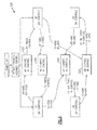
- Figure 4 illustrates a state transition chart for a two channel, four controller system 200 configured to operate as an equivalent four channel system.
- Each of the four possible no-control microprocessor in-control states 222, 224, 226, 228 is entered into under varying conditions.
- each no-control microprocessor in-control state 222, 224, 226, 228 has a corresponding control microprocessor A1, A2, B1, B2 that assumes control of the system 200 when the system enters the no-control microprocessor in-control state 222, 224, 226, 228.
- control microprocessors A1, B1 In a system, such as the one illustrated in Figure 4 , that favors two control microprocessors A1, B1 over the other control microprocessors A2, B2.
- the favored control microprocessors A1, B1 are referred to as “primary control microprocessors” and the remaining control microprocessors A2, B2 are referred to as "secondary control microprocessors.”
- Which primary control microprocessor A1, B1 starts in-control of the system 200 is determined by a default condition.
- the power-up default channel logic alternately places control microprocessor A1 in-control, or control microprocessor B1 in-control.
- control microprocessor A1 if control microprocessor A1 is in-control, and enters a failure state, or otherwise becomes unhealthy, and control microprocessor B1 is healthy, the system 200 enters the no-channel in-control state 222, from which primary control microprocessor B1 assumes control of the controlled device. Similarly, if control microprocessor B1 is in-control of the system and enters a failure state, or otherwise becomes unhealthy, and control microprocessor A1 is healthy, the system 200 enters the no-control microprocessor in-control state 224, from which control microprocessor A1 assumes control of the controlled device.
- control microprocessor A1 is in-control of the system 200 and enters a failure state, or otherwise becomes unhealthy and control microprocessor B1 is not healthy
- the system 200 enters the control microprocessor in-control state 226, from which the secondary control microprocessor A2 that is local to the primary control microprocessor A1 that was immediately previously in-control of the controlled device takes control.
- control microprocessor B1 is in-control of the system 200 and enters a failure state, and control microprocessor A1 is not healthy
- the system 200 enters the no-control microprocessor in-control state 228, from which the secondary control microprocessor B2 that is local to the primary control microprocessor B1 that was immediately previously in-control of the controlled device takes control.
- the system 200 enters the no-control microprocessor in-control state 228, from which the secondary control microprocessor B2 that is remote from the previously in-control secondary control microprocessor A2 takes control of the controlled device.
- the system 200 enters the no-control microprocessor in-control state 226, from which the secondary control microprocessor A2 that is remote from the previously in-control secondary control microprocessor B2 takes control of the controlled device.
- control microprocessors A1, A2, B1, B2 fail during operation, then the system shuts off and the controlled device enters a default state.
- the default state of the uncontrolled device is to cease operation by entering a fail-safe condition.
Landscapes
- Engineering & Computer Science (AREA)
- Physics & Mathematics (AREA)
- General Physics & Mathematics (AREA)
- Theoretical Computer Science (AREA)
- Automation & Control Theory (AREA)
- Quality & Reliability (AREA)
- General Engineering & Computer Science (AREA)
- Hardware Redundancy (AREA)
- Safety Devices In Control Systems (AREA)
- Time-Division Multiplex Systems (AREA)
Applications Claiming Priority (1)
| Application Number | Priority Date | Filing Date | Title |
|---|---|---|---|
| US13/239,791 US9625894B2 (en) | 2011-09-22 | 2011-09-22 | Multi-channel control switchover logic |
Publications (3)
| Publication Number | Publication Date |
|---|---|
| EP2573636A2 true EP2573636A2 (fr) | 2013-03-27 |
| EP2573636A3 EP2573636A3 (fr) | 2016-04-20 |
| EP2573636B1 EP2573636B1 (fr) | 2023-01-25 |
Family
ID=47178454
Family Applications (1)
| Application Number | Title | Priority Date | Filing Date |
|---|---|---|---|
| EP12183922.9A Active EP2573636B1 (fr) | 2011-09-22 | 2012-09-11 | Logique de commutation de contrôle à canaux multiples |
Country Status (2)
| Country | Link |
|---|---|
| US (1) | US9625894B2 (fr) |
| EP (1) | EP2573636B1 (fr) |
Cited By (4)
| Publication number | Priority date | Publication date | Assignee | Title |
|---|---|---|---|---|
| EP2801874A1 (fr) * | 2013-05-06 | 2014-11-12 | Hamilton Sundstrand Corporation | Logique de commutation de commande à canaux multiples |
| CN105513523A (zh) * | 2016-01-29 | 2016-04-20 | 北京航星力源科技有限公司 | 一种用于电力电子设备的自动多功能显示电路 |
| CN108780307A (zh) * | 2016-03-15 | 2018-11-09 | 赛峰电子与防务公司 | 致动设备以及相关联的控制和监视板 |
| RU2848964C1 (ru) * | 2025-03-27 | 2025-10-21 | Публичное акционерное общество "Федеральная сетевая компания - Россети" | Электоральный способ активации центрального управляющего модуля в системе управления с автоматическим резервированием |
Families Citing this family (11)
| Publication number | Priority date | Publication date | Assignee | Title |
|---|---|---|---|---|
| EP2639660A1 (fr) * | 2012-03-16 | 2013-09-18 | Siemens Aktiengesellschaft | Procédé et système pour la transition de contrôleurs |
| DE102014100970A1 (de) * | 2014-01-28 | 2015-07-30 | Pilz Gmbh & Co. Kg | Verfahren und Vorrichtung zum sicheren Abschalten einer elektrischen Last |
| US10455654B1 (en) * | 2014-05-28 | 2019-10-22 | Cooper Technologies Company | Distributed low voltage power systems |
| US9912733B2 (en) * | 2014-07-31 | 2018-03-06 | General Electric Company | System and method for maintaining the health of a control system |
| FR3025617B1 (fr) * | 2014-09-05 | 2016-12-16 | Sagem Defense Securite | Architecture bi-voies |
| US9702937B2 (en) * | 2015-02-17 | 2017-07-11 | Lg Chem, Ltd. | Contactor control system |
| US20180124587A1 (en) * | 2015-03-23 | 2018-05-03 | Romano Rapallini | Network device, computer network and method for controlling environments |
| US10332708B2 (en) | 2015-12-09 | 2019-06-25 | Thales Canada Inc | Seamless switchover system and method |
| RU2657166C1 (ru) * | 2017-04-17 | 2018-06-08 | Российская Федерация, от имени которой выступает Государственная корпорация по атомной энергии "Росатом" | Самодиагностируемая бортовая вычислительная система с резервированием замещением |
| US10671067B2 (en) * | 2018-01-15 | 2020-06-02 | Qualcomm Incorporated | Managing limited safe mode operations of a robotic vehicle |
| RU193697U1 (ru) * | 2019-08-07 | 2019-11-11 | Акционерное общество "Научно-производственный центр "Полюс" | Резервированный контроллер для систем электропитания космического аппарата |
Family Cites Families (23)
| Publication number | Priority date | Publication date | Assignee | Title |
|---|---|---|---|---|
| US4029952A (en) | 1973-11-06 | 1977-06-14 | Westinghouse Electric Corporation | Electric power plant having a multiple computer system for redundant control of turbine and steam generator operation |
| US3978659A (en) | 1975-02-19 | 1976-09-07 | Westinghouse Electric Corporation | Bumpless transfer in shifting control command between the primary and backup control systems of a gas turbine power plant |
| US4358823A (en) | 1977-03-25 | 1982-11-09 | Trw, Inc. | Double redundant processor |
| US4521871A (en) * | 1982-04-12 | 1985-06-04 | Allen-Bradley Company | Programmable controller with back-up capability |
| US4562528A (en) | 1982-10-06 | 1985-12-31 | Mitsubishi Denki Kabushiki Kaisha | Backup control apparatus |
| US4797884A (en) | 1986-09-29 | 1989-01-10 | Texas Instruments Incorporated | Redundant device control unit |
| US5128943A (en) | 1986-10-24 | 1992-07-07 | United Technologies Corporation | Independent backup mode transfer and mechanism for digital control computers |
| US4807516A (en) * | 1987-04-23 | 1989-02-28 | The Boeing Company | Flight control system employing three controllers operating a dual actuator |
| US4937777A (en) | 1987-10-07 | 1990-06-26 | Allen-Bradley Company, Inc. | Programmable controller with multiple task processors |
| US4887214A (en) * | 1987-10-27 | 1989-12-12 | The Boeing Company | Flight control system employing two dual controllers operating a dual actuator |
| US4890284A (en) | 1988-02-22 | 1989-12-26 | United Technologies Corporation | Backup control system (BUCS) |
| US5274554A (en) * | 1991-02-01 | 1993-12-28 | The Boeing Company | Multiple-voting fault detection system for flight critical actuation control systems |
| US5192873A (en) | 1991-02-26 | 1993-03-09 | United Technologies Automotive, Inc. | Fail-operational control system for vehicle loads |
| US5279107A (en) | 1992-06-30 | 1994-01-18 | United Technologies Corporation | Fuel control system with fuel metering valve fault accommodation |
| US6845467B1 (en) | 2001-02-13 | 2005-01-18 | Cisco Systems Canada Co. | System and method of operation of dual redundant controllers |
| US7392426B2 (en) | 2004-06-15 | 2008-06-24 | Honeywell International Inc. | Redundant processing architecture for single fault tolerance |
| US7328371B1 (en) | 2004-10-15 | 2008-02-05 | Advanced Micro Devices, Inc. | Core redundancy in a chip multiprocessor for highly reliable systems |
| US20060236168A1 (en) | 2005-04-01 | 2006-10-19 | Honeywell International Inc. | System and method for dynamically optimizing performance and reliability of redundant processing systems |
| CA2637226A1 (fr) * | 2006-01-17 | 2007-07-26 | Gulfstream Aerospace Corporation | Appareil et procede de commande de secours utilises dans un systeme de commande de vol distribue |
| US7424642B2 (en) * | 2006-04-24 | 2008-09-09 | Gm Global Technology Operations, Inc. | Method for synchronization of a controller |
| US8175759B2 (en) | 2009-06-22 | 2012-05-08 | Honeywell International Inc. | Systems and methods for validating predetermined events in reconfigurable control systems |
| FR2959835B1 (fr) * | 2010-05-10 | 2012-06-15 | Airbus Operations Sas | Systeme de commande de vol et aeronef le comportant |
| US8534599B2 (en) * | 2011-03-31 | 2013-09-17 | Hamilton Sundstrand Corporation | Redundant two stage electro-hydraulic servo actuator control |
-
2011
- 2011-09-22 US US13/239,791 patent/US9625894B2/en active Active
-
2012
- 2012-09-11 EP EP12183922.9A patent/EP2573636B1/fr active Active
Non-Patent Citations (1)
| Title |
|---|
| None |
Cited By (6)
| Publication number | Priority date | Publication date | Assignee | Title |
|---|---|---|---|---|
| EP2801874A1 (fr) * | 2013-05-06 | 2014-11-12 | Hamilton Sundstrand Corporation | Logique de commutation de commande à canaux multiples |
| US9772615B2 (en) | 2013-05-06 | 2017-09-26 | Hamilton Sundstrand Corporation | Multi-channel control switchover logic |
| US10747186B2 (en) | 2013-05-06 | 2020-08-18 | Hamilton Sundstrand Corporation | Multi-channel control switchover logic |
| CN105513523A (zh) * | 2016-01-29 | 2016-04-20 | 北京航星力源科技有限公司 | 一种用于电力电子设备的自动多功能显示电路 |
| CN108780307A (zh) * | 2016-03-15 | 2018-11-09 | 赛峰电子与防务公司 | 致动设备以及相关联的控制和监视板 |
| RU2848964C1 (ru) * | 2025-03-27 | 2025-10-21 | Публичное акционерное общество "Федеральная сетевая компания - Россети" | Электоральный способ активации центрального управляющего модуля в системе управления с автоматическим резервированием |
Also Published As
| Publication number | Publication date |
|---|---|
| EP2573636B1 (fr) | 2023-01-25 |
| EP2573636A3 (fr) | 2016-04-20 |
| US20130079902A1 (en) | 2013-03-28 |
| US9625894B2 (en) | 2017-04-18 |
Similar Documents
| Publication | Publication Date | Title |
|---|---|---|
| EP2573636B1 (fr) | Logique de commutation de contrôle à canaux multiples | |
| CN107187465B (zh) | 一种单元级热备冗余的ato系统架构 | |
| US11904918B2 (en) | Computer interlocking system and switching control method for the same, device, and storage medium | |
| EP2413484A2 (fr) | Système de contrôle de sécurité | |
| US9170569B2 (en) | Method for electing an active master device from two redundant master devices | |
| EP3242169B1 (fr) | Système à contrôleur double | |
| WO2017107665A1 (fr) | Système informatique de sécurité destiné à être utilisé dans la commande de trains | |
| CN105204431B (zh) | 四余度信号监控表决方法和设备 | |
| US10747186B2 (en) | Multi-channel control switchover logic | |
| JP5541246B2 (ja) | 電子制御ユニット | |
| CN110967641A (zh) | 蓄电池监控系统及方法 | |
| CN105717787A (zh) | 用于智能电源配电装置的双余度控制系统及其控制方法 | |
| KR101448013B1 (ko) | 항공기용 다중 컴퓨터의 고장 허용 장치 및 방법 | |
| EP3242171A1 (fr) | Système de commande redondant | |
| US9178355B2 (en) | Cross communication arrangement for multiple solid state power controller channels | |
| KR100380658B1 (ko) | 삼중화 제어장치의 직렬통신을 이용한 출력장치와 그제어방법 | |
| US20220128965A1 (en) | Control Device With Guard Module | |
| US7627774B2 (en) | Redundant manager modules to perform management tasks with respect to an interconnect structure and power supplies | |
| JP2013239034A (ja) | 系切替制御装置及び二重化システム | |
| US9787532B2 (en) | Module, system and method of switching modules | |
| JP6274436B2 (ja) | 二重化制御システム | |
| CN104656478A (zh) | 一种多电源模块的控制电路及控制方法 | |
| JP2009296260A (ja) | データ伝送装置 | |
| JP2011248625A (ja) | 制御装置の故障診断回路および故障診断方法 | |
| US20170155546A1 (en) | Duplex control device and duplex system |
Legal Events
| Date | Code | Title | Description |
|---|---|---|---|
| PUAI | Public reference made under article 153(3) epc to a published international application that has entered the european phase |
Free format text: ORIGINAL CODE: 0009012 |
|
| AK | Designated contracting states |
Kind code of ref document: A2 Designated state(s): AL AT BE BG CH CY CZ DE DK EE ES FI FR GB GR HR HU IE IS IT LI LT LU LV MC MK MT NL NO PL PT RO RS SE SI SK SM TR |
|
| AX | Request for extension of the european patent |
Extension state: BA ME |
|
| PUAL | Search report despatched |
Free format text: ORIGINAL CODE: 0009013 |
|
| AK | Designated contracting states |
Kind code of ref document: A3 Designated state(s): AL AT BE BG CH CY CZ DE DK EE ES FI FR GB GR HR HU IE IS IT LI LT LU LV MC MK MT NL NO PL PT RO RS SE SI SK SM TR |
|
| AX | Request for extension of the european patent |
Extension state: BA ME |
|
| RIC1 | Information provided on ipc code assigned before grant |
Ipc: G05B 9/03 20060101ALI20160316BHEP Ipc: G06F 11/16 20060101ALI20160316BHEP Ipc: G05B 19/042 20060101AFI20160316BHEP |
|
| 17P | Request for examination filed |
Effective date: 20161014 |
|
| RBV | Designated contracting states (corrected) |
Designated state(s): AL AT BE BG CH CY CZ DE DK EE ES FI FR GB GR HR HU IE IS IT LI LT LU LV MC MK MT NL NO PL PT RO RS SE SI SK SM TR |
|
| STAA | Information on the status of an ep patent application or granted ep patent |
Free format text: STATUS: EXAMINATION IS IN PROGRESS |
|
| 17Q | First examination report despatched |
Effective date: 20170412 |
|
| REG | Reference to a national code |
Ref country code: DE Ref legal event code: R079 Ref document number: 602012079243 Country of ref document: DE Free format text: PREVIOUS MAIN CLASS: G05B0023020000 Ipc: G05B0019042000 |
|
| GRAP | Despatch of communication of intention to grant a patent |
Free format text: ORIGINAL CODE: EPIDOSNIGR1 |
|
| STAA | Information on the status of an ep patent application or granted ep patent |
Free format text: STATUS: GRANT OF PATENT IS INTENDED |
|
| RIC1 | Information provided on ipc code assigned before grant |
Ipc: G06F 11/20 20060101ALI20220729BHEP Ipc: G05B 19/042 20060101AFI20220729BHEP |
|
| INTG | Intention to grant announced |
Effective date: 20220830 |
|
| RAP3 | Party data changed (applicant data changed or rights of an application transferred) |
Owner name: HAMILTON SUNDSTRAND CORPORATION |
|
| GRAS | Grant fee paid |
Free format text: ORIGINAL CODE: EPIDOSNIGR3 |
|
| GRAA | (expected) grant |
Free format text: ORIGINAL CODE: 0009210 |
|
| STAA | Information on the status of an ep patent application or granted ep patent |
Free format text: STATUS: THE PATENT HAS BEEN GRANTED |
|
| AK | Designated contracting states |
Kind code of ref document: B1 Designated state(s): AL AT BE BG CH CY CZ DE DK EE ES FI FR GB GR HR HU IE IS IT LI LT LU LV MC MK MT NL NO PL PT RO RS SE SI SK SM TR |
|
| REG | Reference to a national code |
Ref country code: GB Ref legal event code: FG4D |
|
| REG | Reference to a national code |
Ref country code: CH Ref legal event code: EP |
|
| REG | Reference to a national code |
Ref country code: AT Ref legal event code: REF Ref document number: 1546304 Country of ref document: AT Kind code of ref document: T Effective date: 20230215 Ref country code: IE Ref legal event code: FG4D |
|
| REG | Reference to a national code |
Ref country code: DE Ref legal event code: R096 Ref document number: 602012079243 Country of ref document: DE |
|
| REG | Reference to a national code |
Ref country code: LT Ref legal event code: MG9D |
|
| REG | Reference to a national code |
Ref country code: NL Ref legal event code: MP Effective date: 20230125 |
|
| REG | Reference to a national code |
Ref country code: AT Ref legal event code: MK05 Ref document number: 1546304 Country of ref document: AT Kind code of ref document: T Effective date: 20230125 |
|
| P01 | Opt-out of the competence of the unified patent court (upc) registered |
Effective date: 20230522 |
|
| PG25 | Lapsed in a contracting state [announced via postgrant information from national office to epo] |
Ref country code: NL Free format text: LAPSE BECAUSE OF FAILURE TO SUBMIT A TRANSLATION OF THE DESCRIPTION OR TO PAY THE FEE WITHIN THE PRESCRIBED TIME-LIMIT Effective date: 20230125 |
|
| PG25 | Lapsed in a contracting state [announced via postgrant information from national office to epo] |
Ref country code: RS Free format text: LAPSE BECAUSE OF FAILURE TO SUBMIT A TRANSLATION OF THE DESCRIPTION OR TO PAY THE FEE WITHIN THE PRESCRIBED TIME-LIMIT Effective date: 20230125 Ref country code: PT Free format text: LAPSE BECAUSE OF FAILURE TO SUBMIT A TRANSLATION OF THE DESCRIPTION OR TO PAY THE FEE WITHIN THE PRESCRIBED TIME-LIMIT Effective date: 20230525 Ref country code: NO Free format text: LAPSE BECAUSE OF FAILURE TO SUBMIT A TRANSLATION OF THE DESCRIPTION OR TO PAY THE FEE WITHIN THE PRESCRIBED TIME-LIMIT Effective date: 20230425 Ref country code: LV Free format text: LAPSE BECAUSE OF FAILURE TO SUBMIT A TRANSLATION OF THE DESCRIPTION OR TO PAY THE FEE WITHIN THE PRESCRIBED TIME-LIMIT Effective date: 20230125 Ref country code: LT Free format text: LAPSE BECAUSE OF FAILURE TO SUBMIT A TRANSLATION OF THE DESCRIPTION OR TO PAY THE FEE WITHIN THE PRESCRIBED TIME-LIMIT Effective date: 20230125 Ref country code: HR Free format text: LAPSE BECAUSE OF FAILURE TO SUBMIT A TRANSLATION OF THE DESCRIPTION OR TO PAY THE FEE WITHIN THE PRESCRIBED TIME-LIMIT Effective date: 20230125 Ref country code: ES Free format text: LAPSE BECAUSE OF FAILURE TO SUBMIT A TRANSLATION OF THE DESCRIPTION OR TO PAY THE FEE WITHIN THE PRESCRIBED TIME-LIMIT Effective date: 20230125 Ref country code: AT Free format text: LAPSE BECAUSE OF FAILURE TO SUBMIT A TRANSLATION OF THE DESCRIPTION OR TO PAY THE FEE WITHIN THE PRESCRIBED TIME-LIMIT Effective date: 20230125 |
|
| PG25 | Lapsed in a contracting state [announced via postgrant information from national office to epo] |
Ref country code: SE Free format text: LAPSE BECAUSE OF FAILURE TO SUBMIT A TRANSLATION OF THE DESCRIPTION OR TO PAY THE FEE WITHIN THE PRESCRIBED TIME-LIMIT Effective date: 20230125 Ref country code: PL Free format text: LAPSE BECAUSE OF FAILURE TO SUBMIT A TRANSLATION OF THE DESCRIPTION OR TO PAY THE FEE WITHIN THE PRESCRIBED TIME-LIMIT Effective date: 20230125 Ref country code: IS Free format text: LAPSE BECAUSE OF FAILURE TO SUBMIT A TRANSLATION OF THE DESCRIPTION OR TO PAY THE FEE WITHIN THE PRESCRIBED TIME-LIMIT Effective date: 20230525 Ref country code: GR Free format text: LAPSE BECAUSE OF FAILURE TO SUBMIT A TRANSLATION OF THE DESCRIPTION OR TO PAY THE FEE WITHIN THE PRESCRIBED TIME-LIMIT Effective date: 20230426 Ref country code: FI Free format text: LAPSE BECAUSE OF FAILURE TO SUBMIT A TRANSLATION OF THE DESCRIPTION OR TO PAY THE FEE WITHIN THE PRESCRIBED TIME-LIMIT Effective date: 20230125 |
|
| REG | Reference to a national code |
Ref country code: DE Ref legal event code: R097 Ref document number: 602012079243 Country of ref document: DE |
|
| PG25 | Lapsed in a contracting state [announced via postgrant information from national office to epo] |
Ref country code: SM Free format text: LAPSE BECAUSE OF FAILURE TO SUBMIT A TRANSLATION OF THE DESCRIPTION OR TO PAY THE FEE WITHIN THE PRESCRIBED TIME-LIMIT Effective date: 20230125 Ref country code: RO Free format text: LAPSE BECAUSE OF FAILURE TO SUBMIT A TRANSLATION OF THE DESCRIPTION OR TO PAY THE FEE WITHIN THE PRESCRIBED TIME-LIMIT Effective date: 20230125 Ref country code: EE Free format text: LAPSE BECAUSE OF FAILURE TO SUBMIT A TRANSLATION OF THE DESCRIPTION OR TO PAY THE FEE WITHIN THE PRESCRIBED TIME-LIMIT Effective date: 20230125 Ref country code: DK Free format text: LAPSE BECAUSE OF FAILURE TO SUBMIT A TRANSLATION OF THE DESCRIPTION OR TO PAY THE FEE WITHIN THE PRESCRIBED TIME-LIMIT Effective date: 20230125 Ref country code: CZ Free format text: LAPSE BECAUSE OF FAILURE TO SUBMIT A TRANSLATION OF THE DESCRIPTION OR TO PAY THE FEE WITHIN THE PRESCRIBED TIME-LIMIT Effective date: 20230125 |
|
| PG25 | Lapsed in a contracting state [announced via postgrant information from national office to epo] |
Ref country code: SK Free format text: LAPSE BECAUSE OF FAILURE TO SUBMIT A TRANSLATION OF THE DESCRIPTION OR TO PAY THE FEE WITHIN THE PRESCRIBED TIME-LIMIT Effective date: 20230125 |
|
| PLBE | No opposition filed within time limit |
Free format text: ORIGINAL CODE: 0009261 |
|
| STAA | Information on the status of an ep patent application or granted ep patent |
Free format text: STATUS: NO OPPOSITION FILED WITHIN TIME LIMIT |
|
| 26N | No opposition filed |
Effective date: 20231026 |
|
| PG25 | Lapsed in a contracting state [announced via postgrant information from national office to epo] |
Ref country code: SI Free format text: LAPSE BECAUSE OF FAILURE TO SUBMIT A TRANSLATION OF THE DESCRIPTION OR TO PAY THE FEE WITHIN THE PRESCRIBED TIME-LIMIT Effective date: 20230125 |
|
| REG | Reference to a national code |
Ref country code: CH Ref legal event code: PL |
|
| PG25 | Lapsed in a contracting state [announced via postgrant information from national office to epo] |
Ref country code: LU Free format text: LAPSE BECAUSE OF NON-PAYMENT OF DUE FEES Effective date: 20230911 |
|
| REG | Reference to a national code |
Ref country code: BE Ref legal event code: MM Effective date: 20230930 |
|
| PG25 | Lapsed in a contracting state [announced via postgrant information from national office to epo] |
Ref country code: LU Free format text: LAPSE BECAUSE OF NON-PAYMENT OF DUE FEES Effective date: 20230911 Ref country code: IT Free format text: LAPSE BECAUSE OF FAILURE TO SUBMIT A TRANSLATION OF THE DESCRIPTION OR TO PAY THE FEE WITHIN THE PRESCRIBED TIME-LIMIT Effective date: 20230125 Ref country code: MC Free format text: LAPSE BECAUSE OF FAILURE TO SUBMIT A TRANSLATION OF THE DESCRIPTION OR TO PAY THE FEE WITHIN THE PRESCRIBED TIME-LIMIT Effective date: 20230125 |
|
| REG | Reference to a national code |
Ref country code: IE Ref legal event code: MM4A |
|
| PG25 | Lapsed in a contracting state [announced via postgrant information from national office to epo] |
Ref country code: IE Free format text: LAPSE BECAUSE OF NON-PAYMENT OF DUE FEES Effective date: 20230911 |
|
| PG25 | Lapsed in a contracting state [announced via postgrant information from national office to epo] |
Ref country code: CH Free format text: LAPSE BECAUSE OF NON-PAYMENT OF DUE FEES Effective date: 20230930 |
|
| PG25 | Lapsed in a contracting state [announced via postgrant information from national office to epo] |
Ref country code: IE Free format text: LAPSE BECAUSE OF NON-PAYMENT OF DUE FEES Effective date: 20230911 Ref country code: CH Free format text: LAPSE BECAUSE OF NON-PAYMENT OF DUE FEES Effective date: 20230930 |
|
| PG25 | Lapsed in a contracting state [announced via postgrant information from national office to epo] |
Ref country code: BE Free format text: LAPSE BECAUSE OF NON-PAYMENT OF DUE FEES Effective date: 20230930 |
|
| PG25 | Lapsed in a contracting state [announced via postgrant information from national office to epo] |
Ref country code: BG Free format text: LAPSE BECAUSE OF FAILURE TO SUBMIT A TRANSLATION OF THE DESCRIPTION OR TO PAY THE FEE WITHIN THE PRESCRIBED TIME-LIMIT Effective date: 20230125 |
|
| PG25 | Lapsed in a contracting state [announced via postgrant information from national office to epo] |
Ref country code: BG Free format text: LAPSE BECAUSE OF FAILURE TO SUBMIT A TRANSLATION OF THE DESCRIPTION OR TO PAY THE FEE WITHIN THE PRESCRIBED TIME-LIMIT Effective date: 20230125 |
|
| PG25 | Lapsed in a contracting state [announced via postgrant information from national office to epo] |
Ref country code: CY Free format text: LAPSE BECAUSE OF FAILURE TO SUBMIT A TRANSLATION OF THE DESCRIPTION OR TO PAY THE FEE WITHIN THE PRESCRIBED TIME-LIMIT; INVALID AB INITIO Effective date: 20120911 |
|
| PG25 | Lapsed in a contracting state [announced via postgrant information from national office to epo] |
Ref country code: HU Free format text: LAPSE BECAUSE OF FAILURE TO SUBMIT A TRANSLATION OF THE DESCRIPTION OR TO PAY THE FEE WITHIN THE PRESCRIBED TIME-LIMIT; INVALID AB INITIO Effective date: 20120911 |
|
| PGFP | Annual fee paid to national office [announced via postgrant information from national office to epo] |
Ref country code: DE Payment date: 20250820 Year of fee payment: 14 |
|
| PGFP | Annual fee paid to national office [announced via postgrant information from national office to epo] |
Ref country code: GB Payment date: 20250820 Year of fee payment: 14 |
|
| PGFP | Annual fee paid to national office [announced via postgrant information from national office to epo] |
Ref country code: FR Payment date: 20250820 Year of fee payment: 14 |
|
| PG25 | Lapsed in a contracting state [announced via postgrant information from national office to epo] |
Ref country code: TR Free format text: LAPSE BECAUSE OF FAILURE TO SUBMIT A TRANSLATION OF THE DESCRIPTION OR TO PAY THE FEE WITHIN THE PRESCRIBED TIME-LIMIT Effective date: 20230125 |