EP2573638A2 - Systèmes et procédés pour l'étalonnage de capteur de centrale électrique basé sur l'état - Google Patents
Systèmes et procédés pour l'étalonnage de capteur de centrale électrique basé sur l'état Download PDFInfo
- Publication number
- EP2573638A2 EP2573638A2 EP12184621A EP12184621A EP2573638A2 EP 2573638 A2 EP2573638 A2 EP 2573638A2 EP 12184621 A EP12184621 A EP 12184621A EP 12184621 A EP12184621 A EP 12184621A EP 2573638 A2 EP2573638 A2 EP 2573638A2
- Authority
- EP
- European Patent Office
- Prior art keywords
- power plant
- data
- sensors
- plant sensors
- performance model
- Prior art date
- Legal status (The legal status is an assumption and is not a legal conclusion. Google has not performed a legal analysis and makes no representation as to the accuracy of the status listed.)
- Withdrawn
Links
- 238000000034 method Methods 0.000 title claims abstract description 35
- 230000015556 catabolic process Effects 0.000 claims description 12
- 238000006731 degradation reaction Methods 0.000 claims description 12
- 238000004590 computer program Methods 0.000 claims description 8
- 238000004891 communication Methods 0.000 claims description 5
- 238000001514 detection method Methods 0.000 description 4
- 238000010586 diagram Methods 0.000 description 3
- 239000012530 fluid Substances 0.000 description 3
- 238000012423 maintenance Methods 0.000 description 3
- 238000005516 engineering process Methods 0.000 description 2
- 238000012544 monitoring process Methods 0.000 description 2
- 230000003287 optical effect Effects 0.000 description 2
- 230000005540 biological transmission Effects 0.000 description 1
- 230000000593 degrading effect Effects 0.000 description 1
- 230000000694 effects Effects 0.000 description 1
- 230000006870 function Effects 0.000 description 1
- 230000010354 integration Effects 0.000 description 1
- 238000005259 measurement Methods 0.000 description 1
- 229910052751 metal Inorganic materials 0.000 description 1
- 239000002184 metal Substances 0.000 description 1
- 150000002739 metals Chemical class 0.000 description 1
- 238000012545 processing Methods 0.000 description 1
- 230000003068 static effect Effects 0.000 description 1
Images



Classifications
-
- G—PHYSICS
- G05—CONTROLLING; REGULATING
- G05B—CONTROL OR REGULATING SYSTEMS IN GENERAL; FUNCTIONAL ELEMENTS OF SUCH SYSTEMS; MONITORING OR TESTING ARRANGEMENTS FOR SUCH SYSTEMS OR ELEMENTS
- G05B23/00—Testing or monitoring of control systems or parts thereof
- G05B23/02—Electric testing or monitoring
- G05B23/0205—Electric testing or monitoring by means of a monitoring system capable of detecting and responding to faults
- G05B23/0208—Electric testing or monitoring by means of a monitoring system capable of detecting and responding to faults characterized by the configuration of the monitoring system
Definitions
- Embodiments of the invention relate generally to power plants, and more particularly to systems and methods for condition-based power plant sensor calibration.
- Sensor calibration is a routine activity at power plants to ensure reliable control and operation of the power plants.
- Traditional calibration schedules are fixed or determined by other maintenance schedules. Sensors are checked and calibrated according to the schedule regardless of whether the sensors actually need to be calibrated. On the other hand, sensors that need to be calibrated are not checked and calibrated until the next schedule.
- Disclosed embodiments may include systems and methods for condition-based power plant sensor calibration.
- a method for condition-based power plant sensor calibration includes receiving data from one or more power plant sensors; reconciling errors detected within the data from the one or more power plant sensors; calibrating the one or more power plant sensors based at least in part on the errors detected within the data; generating at least one performance model based at least in part on the reconciled data from the one or more power plant sensors; detecting anomalies within the at least one performance model; and tuning the at least one performance model to account for the anomalies.
- the invention resides in a computer program comprising computer program code means adapted to perform the above method and in the computer program embodied on a computer-readable medium.
- the system includes a computer processor and a memory in communication with the computer processor and operable to store the above computer program.
- Illustrative embodiments of the invention are directed to, among other things, systems and methods for condition-based power plant sensor calibration. Certain illustrative embodiments of the invention may be directed to receiving data from one or more power plant sensors; reconciling errors detected within the data from the one or more power plant sensors; calibrating the one or more power plant sensors based at least in part on the errors detected within the data; generating at least one performance model based at least in part on the reconciled data from the one or more power plant sensors; detecting anomalies within the at least one performance model; and tuning the at least one performance model to account for the anomalies.
- reconciling errors detected within the data from the one or more power plant sensors can be based at least in part on accessing at least one database of calibration history and trends for the one or more power plant sensors.
- the errors detected within the data from the one or more power plant sensors can be based at least in part on sensor drifting.
- an optimal calibration interval can be determined for the one or more power plant sensors based at least in part on the errors detected within the data.
- detecting anomalies within the at least one performance model can be based at least in part on accessing at least one database of known performance models or actual power plant performance results.
- the detected anomalies within the at least one performance model can be based at least in part on equipment performance degradation.
- FIG. 1 is a schematic illustrating details of an example data flow 100 for implementing condition-based power plant sensor calibration.
- one or more power plant sensors 102 monitor various components of the power plant.
- the one or more power plant sensors 102 may transmit data regarding the various components of the power plant to the power plant control system 104 and the power plant historian 106.
- the data received from the one or more power plant sensors 102 may be analyzed for errors. Errors detected within the data from the one or more power plant sensors 102 can be reconciled 108 based at least in part on accessing at least one database 116 of calibration history and trends for the one or more power plant sensors 102, i.e., the received data from one or more power plant sensors 102 may be compared to the calibration history and trends for the one or more power plant sensors 102 stored in the database 116 to detect errors. In certain embodiments, the errors detected within the data from the one or more power plant sensors 102 can be based at least in part on sensor drifting.
- the errors detected within the data from the one or more power plant sensors 102 can be reconciled 108, meaning, for example, if one or more power plant sensors 102 are providing conflicting data regarding components of the power plant, the one or more power plant sensors 102 that are known to be more reliable, based at least in part on the calibration history and trends of the one or more power plant sensors 102 stored in the database 116, can be given more weight when calculating, for example, a performance model.
- At least one performance model 110 can be generated based at least in part on the reconciled data 108 from the one or more power plant sensors 102. As discussed above, the random errors detected in the data received from the one or more power plant sensors 102 can be reconciled. The reconciled data 108 provides consistent input data for generating the at least one performance model 110. The at least one performance model 110 is used to model power plant performance as a whole or to model the performance of individual components of the power plant.
- the at least one performance model 110 is analyzed for anomalies 112. For example, detecting anomalies 112 within the at least one performance model 110 can be based at least in part on accessing at least one database 116 of known performance models or actual power plant performance results. The at least one performance model 110 may then be compared to the known performance models or actual power plant performance results stored in the database 116 to detect anomalies 112. The detected anomalies 112 within the at least one performance model 110 can be based at least in part on equipment performance degradation.
- the one or more power plant sensors are calibrated 118 based at least in part on the errors detected and reconciled 108 within the data. For example, when errors are detected in the data received from the one or more power plant sensors 102 as discussed above, a calibration request 114 may be generated. A notification 120 may then be provided to calibrate 118 the one or more power plant sensors 102 to account for sensor drifting. Similarly, when anomalies are detected in the at least one performance model 110 as discussed above, a tuning request 114 may be generated. A notification 120 may then be provided to tune the at least one performance model 110 to account for the power plant equipment degradation. Moreover, in certain embodiments, when anomalies are detected in the at least one performance model 110, a sensor calibration request 14 may also be generated to ensure that the anomaly is the result of true performance degradation and not a sensor issue.
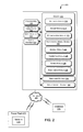
- FIG. 2 provides an illustrative overview of a system, including one computing device 200, according to an embodiment of the invention.
- the computing device 200 may be configured as any suitable computing device capable of implementing the disclosed features, and accompanying methods, such as, but not limited to, those described with reference to FIG. 2 .
- suitable computing devices may include personal computers (PCs), servers, server farms, data centers, or any other device capable of storing and executing all or part of the disclosed features.
- the computing device 200 comprises at least a memory 202 and one or more processing units (or processor(s)) 204.
- the processor(s) 204 may be implemented as appropriate in hardware, software, firmware, or combinations thereof.
- Software or firmware implementations of the processor(s) 204 may include computer-executable or machine-executable instructions written in any suitable programming language to perform the various functions described.
- Memory 202 may store program instructions that are loadable and executable on the processor(s) 204, as well as data generated during the execution of these programs.
- memory 202 may be volatile (such as random access memory (RAM)) and/or non-volatile (such as read-only memory (ROM), flash memory, etc.).
- RAM random access memory
- ROM read-only memory
- the computing device or server may also include additional removable storage 206 and/or non-removable storage 208 including, but not limited to, magnetic storage, optical disks, and/or tape storage.
- the disk drives and their associated computer-readable media may provide non-volatile storage of computer-readable instructions, data structures, program modules, and other data for the computing devices.
- the memory 202 may include multiple different types of memory, such as static random access memory (SRAM), dynamic random access memory (DRAM), or ROM.
- SRAM static random access memory
- DRAM dynamic random access memory
- ROM read-only memory
- Memory 202, removable storage 206, and non-removable storage 208 are all examples of computer-readable storage media.
- computer-readable storage media may include volatile and non-volatile, removable and non-removable media implemented in any method or technology for storage of information such as computer-readable instructions, data structures, program modules or other data.
- Memory 202, removable storage 206, and non-removable storage 208 are all examples of computer storage media.
- Additional types of computer storage media include, but are not limited to, programmable random access memory (PRAM), SRAM, DRAM, RAM, ROM, electrically erasable programmable read-only memory (EEPROM), flash memory or other memory technology, compact disc read-only memory (CD-ROM), digital versatile discs (DVD) or other optical storage, magnetic cassettes, magnetic tape, magnetic disk storage or other magnetic storage devices, or any other medium which can be used to store the desired information and which can be accessed by the server or other computing device. Combinations of any of above should also be included within the scope of computer-readable media.
- computer-readable communication media may include computer-readable instructions, program modules, or other data transmitted within a data signal, such as a carrier wave, or other transmission.
- the computing device 200 may also contain communication connection(s) 210 that allow the computing device 200 to communicate with a stored database, another computing device or server, user terminals, and/or other devices on a network 230.
- the computing device 200 may also include input device(s) 212, such as a keyboard, mouse, pen, voice input device, touch input device, etc., and output device(s) 214, such as a display, speakers, printer, etc.
- the memory 202 may include an operating system 216 and one or more application programs or services for implementing the features disclosed herein including a sensor module 218.
- the sensor module 218 may be configured to receive data from one or more power plant sensors 234. Additionally, the sensor module 218 may store the received data from the one or more power plant sensors 234 in the memory 202.
- An example of data received by the sensor module 218 can include measurements of various components of the power plant 232.
- the sensor module 218 can receive data from one or more power plant sensors 234 monitoring turbines, pumps, heat exchangers, and/or other components of the power plant 232.
- the data collected or otherwise received from the one or more power plant sensors 234 can include, but is not limited to, one or more: temperatures of various fluids and metals of the power plant 232; pressures of various fluids and equipment contained within systems and subsystems of the power plant 232; and/or flow rates of various fluids within systems and subsystems of the power plant 232.
- the memory 202 may further include a reconciliation module 220.
- the reconciliation module 220 may be configured to reconcile errors detected within the data from the one or more power plant sensors 234. Additionally, the reconciliation module 220 may store the reconciled data in the memory 202.
- the reconciliation module 220 facilitates consistent data by minimizing random errors prior to generating the performance model discussed below. For example, reconciling errors detected within the data from the one or more power plant sensors 234 can be based at least in part on accessing at least one database 236 of the calibration history and trends for the one or more power plant sensors 234. The received data from the one or more power plant sensors 234 may then be compared to the calibration history and trends for the one or more power plant sensors 234 to detect errors. The reconciliation module 220 may then disregard or give less weight to the data received from the one or more sensors 234 that indicate an error. The errors detected within the data from the one or more power plant sensors 234 can be based at least in part on sensor drifting.
- the memory 202 may also include a calibration module 226.
- the calibration module 226 may be configured to calibrate the one or more power plant sensors 234 based at least in part on the errors detected within the data in reconciliation module 220.
- the calibration module 226 may also be configured to calibrate the one or more power plant sensors 234 when anomalies are detected in the performance model anomaly module 224 as discussed below to ensure that the anomaly is the result of true performance degradation and not a sensor issue.
- the calibration module 226 my further be configured to remotely calibrate the one or more power plant sensors 234 or issue an alert or work order for the one or more sensors 234 to be manually calibrated.
- the calibration module may also be configured to determine an optimal maintenance or calibration interval for the one or more power plant sensors 234 based at least in part on the errors detected within the data in reconciliation module 220.
- the memory 202 may also include a performance model module 222.
- the performance model module 222 may be configured to generate at least one performance model based at least in part on the reconciled data from the one or more power plant sensors 234 in reconciliation module 220. As discussed above, the reconciliation module 220 minimizes random errors from the data received from the one or more power plant sensors 234. The reconciliation module 220 delivers consistent input data for generating the at least one performance model.
- the at least one performance model is used to model power plant performance as a whole or to model the performance of individual components of the power plant.
- the memory 202 may also include an anomaly module 224.
- the anomaly module 224 may be configured to detect anomalies within the at least one performance model. Additionally, the anomaly module 224 may store the detected anomalies in the memory 202. For example, detecting anomalies within the at least one performance model can be based at least in part on accessing at least one database 236 of known performance models or actual power plant performance results. The at least one performance model may then be compared to the known performance models or actual power plant performance results to detect anomalies. The detected anomalies within the at least one performance model can be based at least in part on equipment performance degradation. Using this information, an optimal maintenance or calibration interval may be determined for degrading or malfunctioning power plant equipment.
- the memory 202 may also include a tuning module 228.
- the tuning module 228 may be configured for tuning the at least one performance model to account for the anomalies.
- the anomalies in the at least one performance model can be based at least in part on power plant equipment degradation. Accordingly, the at least one performance model can be tuned or adjusted to account for the power plant equipment degradation.
- the memory 202 may also include a rule engine module 238.
- the rule engine module 238 may be configured to provide an overall system level application.
- the system level application can link data flow/information, execute rules, and manage notifications/alarms regarding the one or more sensors and/or performance models.
- program modules include routines, programs, objects, components, data structures, etc., for performing particular tasks or implementing particular abstract data types.
- program modules and the like may be executed as native code or may be downloaded and executed, such as in a virtual machine or other just-in-time compilation execution environment.
- functionality of the program modules may be combined or distributed as desired in various embodiments.
- An implementation of these modules and techniques may be stored on some form of computer-readable storage media.
- the example computing device 200 shown in FIG. 2 is provided by way of example only. Numerous other operating environments, system architectures, and device configurations are possible. Accordingly, embodiments of the present disclosure should not be construed as being limited to any particular operating environment, system architecture, or device configuration.
- the computing device 200 can be in communication with the power plant 232 via a network 230.
- the power plant 232 may include one or more sensors 234 or other means or devices for monitoring, detecting, and/or transmitting data regarding the power plant as a whole or individual components of the power plant.
- Certain illustrative embodiments of the invention may be directed towards the computing device 200 determining power plant equipment performance degradation and/or one or more power plant sensors drifting through data reconciliation and anomaly detection.
- an optimal calibration interval may be determined for the one or more power plant sensors based at least in part on the errors detected within the data.
- FIG. 3 is a graph 300 illustrating the calibration history of one or more power plant sensors.
- the y-axis 302 of the graph 300 indicates error tolerance.
- the x-axis 304 of graph 300 indicates time.
- the upper horizontal line 306 is the upper error tolerance
- the lower horizontal line 308 is the lower error tolerance.
- the calibration results for the one or more power plant sensors are plotted 310 on the graph 300.
- the sensor performance can be analyzed. In particular, for example, sensor drift can be monitored by analyzing when and how often the sensor falls outside of the error tolerances. Moreover, if a particular sensor includes data outside the error tolerances, that sensor may be disregarded or given less weight when reconciling the errors within the data received by the one or more power plant sensors.
- FIG. 4 illustrates an example flow diagram of a method 400 for condition based power plant sensor calibration, in accordance with an embodiment of the invention.
- the illustrative computing device 200 of FIG. 2 and/or one or more modules of the illustrative computing device 200 may perform the described operations of method 400.
- the method 400 may begin at block 402 of FIG. 4 in which the method 400 may include receiving data from one or more power plant sensors. Further, at block 404, the method 400 may include reconciling errors detected within the data from the one or more power plant sensors. At block 406, the method 400 may include calibrating the one or more power plant sensors based at least in part on the errors detected within the data. At block 408, the method 400 may include generating at least one performance model based at least in part on the reconciled data from the one or more power plant sensors. At block 410, the method 400 may include detecting anomalies within the at least one performance model. At block 412, the method 400 may include tuning the at least one performance model to account for the anomalies. Moreover, at block 414, the method 400 may include determining an optimal calibration interval for the one or more power plant sensors based at least in part on the errors detected within the data.
Landscapes
- Physics & Mathematics (AREA)
- General Physics & Mathematics (AREA)
- Engineering & Computer Science (AREA)
- Automation & Control Theory (AREA)
- Testing And Monitoring For Control Systems (AREA)
- Testing Or Calibration Of Command Recording Devices (AREA)
Applications Claiming Priority (1)
| Application Number | Priority Date | Filing Date | Title |
|---|---|---|---|
| US13/245,486 US8892382B2 (en) | 2011-09-26 | 2011-09-26 | Systems and methods for condition-based power plant sensor calibration |
Publications (2)
| Publication Number | Publication Date |
|---|---|
| EP2573638A2 true EP2573638A2 (fr) | 2013-03-27 |
| EP2573638A3 EP2573638A3 (fr) | 2017-06-07 |
Family
ID=47262971
Family Applications (1)
| Application Number | Title | Priority Date | Filing Date |
|---|---|---|---|
| EP12184621.6A Withdrawn EP2573638A3 (fr) | 2011-09-26 | 2012-09-17 | Systèmes et procédés pour l'étalonnage de capteur de centrale électrique basé sur l'état |
Country Status (3)
| Country | Link |
|---|---|
| US (1) | US8892382B2 (fr) |
| EP (1) | EP2573638A3 (fr) |
| CN (1) | CN103076034B (fr) |
Families Citing this family (5)
| Publication number | Priority date | Publication date | Assignee | Title |
|---|---|---|---|---|
| US11442919B2 (en) | 2015-07-31 | 2022-09-13 | Accenture Global Services Limited | Data reliability analysis |
| US20180218277A1 (en) * | 2017-01-30 | 2018-08-02 | General Electric Company | Systems and methods for reliability monitoring |
| US10346228B2 (en) * | 2017-07-12 | 2019-07-09 | Siemens Aktiengesellschaft | Method and system for deviation detection in sensor datasets |
| FI128841B (en) | 2018-03-22 | 2021-01-15 | Univ Helsinki | Sensor calibration |
| JP6737311B2 (ja) * | 2018-07-30 | 2020-08-05 | 横河電機株式会社 | 検証プログラム、記録媒体、検証装置、検証方法 |
Family Cites Families (11)
| Publication number | Priority date | Publication date | Assignee | Title |
|---|---|---|---|---|
| JPH0731545B2 (ja) * | 1986-11-21 | 1995-04-10 | 動力炉・核燃料開発事業団 | プラントの異常診断方法 |
| US4947355A (en) | 1988-05-05 | 1990-08-07 | John Fluke Mfg. Co., Inc. | Modular electronic instrument system having automated calibration capability |
| US5396440A (en) | 1993-01-12 | 1995-03-07 | The Dow Chemical Company | Optimum calibration frequency determination |
| JP4017272B2 (ja) * | 1998-12-16 | 2007-12-05 | 中国電力株式会社 | プラント状態推定・予測装置及び方法 |
| ATE326717T1 (de) * | 2002-09-26 | 2006-06-15 | Siemens Ag | Vorrichtung und verfahren zur überwachung einer mehrere systeme umfassenden technischen anlage, insbesondere einer kraftwerksanlage |
| US7027953B2 (en) * | 2002-12-30 | 2006-04-11 | Rsl Electronics Ltd. | Method and system for diagnostics and prognostics of a mechanical system |
| US20090043447A1 (en) | 2007-08-07 | 2009-02-12 | General Electric Company | Systems and Methods for Model-Based Sensor Fault Detection and Isolation |
| US7702401B2 (en) | 2007-09-05 | 2010-04-20 | Fisher-Rosemount Systems, Inc. | System for preserving and displaying process control data associated with an abnormal situation |
| JP4922265B2 (ja) * | 2008-08-19 | 2012-04-25 | 株式会社東芝 | プラント監視装置およびプラント監視方法 |
| US20100257838A1 (en) * | 2009-04-09 | 2010-10-14 | General Electric Company | Model based health monitoring of aeroderivatives, robust to sensor failure and profiling |
| JP2011145846A (ja) * | 2010-01-14 | 2011-07-28 | Hitachi Ltd | 異常検知方法、異常検知システム、及び異常検知プログラム |
-
2011
- 2011-09-26 US US13/245,486 patent/US8892382B2/en active Active
-
2012
- 2012-09-17 EP EP12184621.6A patent/EP2573638A3/fr not_active Withdrawn
- 2012-09-25 CN CN201210359224.2A patent/CN103076034B/zh not_active Expired - Fee Related
Non-Patent Citations (1)
| Title |
|---|
| None |
Also Published As
| Publication number | Publication date |
|---|---|
| US8892382B2 (en) | 2014-11-18 |
| US20130080100A1 (en) | 2013-03-28 |
| CN103076034B (zh) | 2016-08-24 |
| CN103076034A (zh) | 2013-05-01 |
| EP2573638A3 (fr) | 2017-06-07 |
Similar Documents
| Publication | Publication Date | Title |
|---|---|---|
| EP3355145A1 (fr) | Système et procédés de surveillance de fiabilité | |
| US10599982B2 (en) | Internet of things based determination of machine reliability and automated maintainenace, repair and operation (MRO) logs | |
| US11334057B2 (en) | Anomaly detection for predictive maintenance and deriving outcomes and workflows based on data quality | |
| US7881815B2 (en) | Method and system for process control | |
| US10489752B2 (en) | Failure mode ranking in an asset management system | |
| US10503145B2 (en) | System and method for asset fleet monitoring and predictive diagnostics using analytics for large and varied data sources | |
| US8892382B2 (en) | Systems and methods for condition-based power plant sensor calibration | |
| US10346228B2 (en) | Method and system for deviation detection in sensor datasets | |
| WO2014116404A1 (fr) | Systèmes et procédés permettant de fournir un compteur de flux de nuage | |
| EP3180706A1 (fr) | Système informatique nuagique et procédé de commande avancée de processus | |
| EP3180667B1 (fr) | Système et procédé de commande de processus avancée | |
| EP3343470A1 (fr) | Dispositif de gestion de maintenance, procédé de gestion de maintenance, programme de gestion de maintenance et support d'informations lisible par ordinateur non transitoire | |
| US10198303B2 (en) | Maintenance system and method for analyzing functional failures of a system | |
| KR20140056952A (ko) | 이상 예측 평가 방법 및 시스템 | |
| US11194685B2 (en) | Recording medium for verifying correlation between test signal and test result signal, verification apparatus and verification method | |
| US12270719B2 (en) | Pressure transmitter long-term drift detection and correction | |
| CN116185774A (zh) | 日志监控安装方法、装置、计算机设备和存储介质 | |
| JP7764872B2 (ja) | プロトコル変換装置、方法、プログラム、及びシステム | |
| US20250165245A1 (en) | Support system, support method, and non-transitory computer readable-medium | |
| US20250298399A1 (en) | Apparatus, systems, and methods to identify pneumatic leaks | |
| EP4478145A1 (fr) | Rapports numérisés de systèmes techniques | |
| US20250146846A1 (en) | Field device and diagnostic method | |
| JP2025148791A (ja) | センサ、管理システム、計測情報生成方法、およびプログラム | |
| CN121605363A (zh) | 对监测数据进行优先级排序 |
Legal Events
| Date | Code | Title | Description |
|---|---|---|---|
| PUAI | Public reference made under article 153(3) epc to a published international application that has entered the european phase |
Free format text: ORIGINAL CODE: 0009012 |
|
| AK | Designated contracting states |
Kind code of ref document: A2 Designated state(s): AL AT BE BG CH CY CZ DE DK EE ES FI FR GB GR HR HU IE IS IT LI LT LU LV MC MK MT NL NO PL PT RO RS SE SI SK SM TR |
|
| AX | Request for extension of the european patent |
Extension state: BA ME |
|
| PUAL | Search report despatched |
Free format text: ORIGINAL CODE: 0009013 |
|
| AK | Designated contracting states |
Kind code of ref document: A3 Designated state(s): AL AT BE BG CH CY CZ DE DK EE ES FI FR GB GR HR HU IE IS IT LI LT LU LV MC MK MT NL NO PL PT RO RS SE SI SK SM TR |
|
| AX | Request for extension of the european patent |
Extension state: BA ME |
|
| RIC1 | Information provided on ipc code assigned before grant |
Ipc: G05B 23/02 20060101AFI20170428BHEP |
|
| PUAL | Search report despatched |
Free format text: ORIGINAL CODE: 0009013 |
|
| STAA | Information on the status of an ep patent application or granted ep patent |
Free format text: STATUS: REQUEST FOR EXAMINATION WAS MADE |
|
| 17P | Request for examination filed |
Effective date: 20171207 |
|
| RBV | Designated contracting states (corrected) |
Designated state(s): AL AT BE BG CH CY CZ DE DK EE ES FI FR GB GR HR HU IE IS IT LI LT LU LV MC MK MT NL NO PL PT RO RS SE SI SK SM TR |
|
| STAA | Information on the status of an ep patent application or granted ep patent |
Free format text: STATUS: THE APPLICATION IS DEEMED TO BE WITHDRAWN |
|
| 18D | Application deemed to be withdrawn |
Effective date: 20210401 |