EP2573672A1 - Système et procédé pour générer une adresse d'entrée de table de fente pour un dispositif de communications - Google Patents
Système et procédé pour générer une adresse d'entrée de table de fente pour un dispositif de communications Download PDFInfo
- Publication number
- EP2573672A1 EP2573672A1 EP12181625A EP12181625A EP2573672A1 EP 2573672 A1 EP2573672 A1 EP 2573672A1 EP 12181625 A EP12181625 A EP 12181625A EP 12181625 A EP12181625 A EP 12181625A EP 2573672 A1 EP2573672 A1 EP 2573672A1
- Authority
- EP
- European Patent Office
- Prior art keywords
- slot
- communications
- counter value
- slot table
- cycle
- Prior art date
- Legal status (The legal status is an assumption and is not a legal conclusion. Google has not performed a legal analysis and makes no representation as to the accuracy of the status listed.)
- Granted
Links
Images


Classifications
-
- H—ELECTRICITY
- H04—ELECTRIC COMMUNICATION TECHNIQUE
- H04L—TRANSMISSION OF DIGITAL INFORMATION, e.g. TELEGRAPHIC COMMUNICATION
- H04L12/00—Data switching networks
- H04L12/28—Data switching networks characterised by path configuration, e.g. LAN [Local Area Networks] or WAN [Wide Area Networks]
- H04L12/40—Bus networks
- H04L12/403—Bus networks with centralised control, e.g. polling
- H04L12/4035—Bus networks with centralised control, e.g. polling in which slots of a TDMA packet structure are assigned based on a contention resolution carried out at a master unit
-
- H—ELECTRICITY
- H04—ELECTRIC COMMUNICATION TECHNIQUE
- H04L—TRANSMISSION OF DIGITAL INFORMATION, e.g. TELEGRAPHIC COMMUNICATION
- H04L47/00—Traffic control in data switching networks
- H04L47/50—Queue scheduling
-
- H—ELECTRICITY
- H04—ELECTRIC COMMUNICATION TECHNIQUE
- H04L—TRANSMISSION OF DIGITAL INFORMATION, e.g. TELEGRAPHIC COMMUNICATION
- H04L12/00—Data switching networks
- H04L12/28—Data switching networks characterised by path configuration, e.g. LAN [Local Area Networks] or WAN [Wide Area Networks]
- H04L12/40—Bus networks
- H04L2012/40208—Bus networks characterized by the use of a particular bus standard
- H04L2012/40241—Flexray
Definitions
- Embodiments of the invention relate generally to address systems and methods and, more particularly, to systems and methods for generating slot table entry addresses for communications devices.
- Communications nodes in an application system can communicate with each other directly or through a communications hub device such as a communications controller.
- a communications controller can connect communications nodes in an automobile system to control communications between the communications nodes in order to improve the robustness of communications of the automobile system.
- the communications nodes can perform a look up in a slot table using slot table entry addresses and check the corresponding slot table entries that contain communications schedule information.
- the communications controller can perform a look up in a slot table using slot table entry addresses and check the corresponding slot table entries that contain communications configuration information of the communications nodes in the time slots.
- a method for generating a slot table entry address for a communications device of a communications network includes processing a slot counter value according to a configuration setting value to produce a processed slot counter value, where the slot counter value identifies a time slot of data communications of the communications network, masking a cycle counter value according to the configuration setting value to generate a masked cycle counter value, where the cycle counter value identifies a communications cycle containing the time slot, and processing the processed slot counter value and the masked cycle counter value to generate a slot table entry address such that a corresponding slot table entry of the time slot of the communications cycle in a slot table is accessed by the communications device at the slot table entry address.
- Other embodiments are also described.
- a system for generating a slot table entry address for a communications device of a communications network includes a first bit processing device configured to process a slot counter value according to a configuration setting value to produce a processed slot counter value, where the slot counter value identifies a time slot of data communications of the communications network, a bit masking device configured to mask a cycle counter value according to the configuration setting value to generate a masked cycle counter value, where the cycle counter value identifies a communications cycle containing the time slot, and a second bit processing device configured to process the processed slot counter value and the masked cycle counter value to generate a slot table entry address such that a corresponding slot table entry of the time slot of the communications cycle in a slot table is accessed by the communications device at the slot table entry address.
- a method for generating a slot table entry address for a FlexRay-compatible communications device of a communications network includes processing a slot counter value according to a configuration setting value to produce a processed slot counter value, where the slot counter value identifies a time slot of data communications of the communications network, masking a cycle counter value according to the configuration setting value to generate a masked cycle counter value, where the cycle counter value identifies a communications cycle containing the time slot, and processing the processed slot counter value and the masked cycle counter value to generate a slot table entry address such that a corresponding slot table entry of the time slot of the communications cycle in a slot table is accessed by the FlexRay-compatible communications device at the slot table entry address.
- Fig. 1 is a schematic block diagram of a communications network 100 in accordance with an embodiment of the invention.
- the communications network can be used for various applications.
- the communications network is used for an automotive application.
- automotive applications include, without limitation, vehicle dynamics such as braking, suspension, steering, driver assistance, intelligent parking assist, adaptive cruise control, fuel control, traction control, intelligent power assisted steering, lane departure warning, electronic power assisted steering and electronic stability control.
- the communications network facilitates communications among communications devices such as electronic controller nodes in an automobile system, which may be located within a single vehicle or distributed across multiple vehicles.
- the communications network 100 includes communications devices 102-1, 102-2, 102-3, 102-4, 102-5, 102-6, 102-7, 102-8 and a communications controller 104.
- the communications network is configured to facilitate communications among the communications devices.
- the communications network is configured to facilitate critical communications (e.g., safety critical communications) among the communications devices.
- critical communications e.g., safety critical communications
- the communications network is shown in Fig. 1 as including eight communications devices, in some other embodiments, the communications network includes more than or less than eight communications devices.
- the communications network is shown in Fig. 1 as including only one communications controller, in some other embodiments, the communications network includes multiple communications controllers.
- the communications devices 102-1, 102-2, 102-3, 102-4, 102-5, 102-6, 102-7, 102-8 of the communications network 100 are configured to transmit and receive data.
- the data transmitted and received by the communications devices can be in any suitable format.
- the data transmitted and received are data frames.
- a data frame includes a header segment, a payload segment used to convey application data, and a trailer segment.
- each of the communications devices may be configured to perform an additional function.
- each of the communications devices may be used to perform an automotive application.
- the communications devices are electronic controller nodes in an automobile system.
- An electronic controller node contains an electronic control unit (ECU), which may be connected to sensors and actuators connected. The ECU typically collects data from the sensors, runs application software, controls the actuators, and communicates to other electronic controller nodes via the communications network.
- ECU electronice control unit
- the communications controller 104 of the communications network 100 is configured to control communications data transmitted on buses or branches in the communications network.
- the communications controller 104 selectively block and selectively forward data received on different data transmission buses or branches in the communications network.
- the communications controller 104 is connected to six buses 108-1, 108-2, 108-3, 108-4, 108-5, 108-6 in the communications network.
- the communications devices 102-1, 102-2 are connected to the bus 108-1
- the communications device 102-3 is connected to the bus 108-2
- the communications device 102-4 is connected to the bus 108-3
- the communications devices 102-5, 102-6 are connected to the bus 108-4
- the communications device 102-7 is connected to the bus 108-5
- the communications device 102-8 is connected to the bus 108-6.
- the six buses are serial communications buses in the communications network.
- the communications controller 104 may be a part of an In-Vehicle Network (IVN) system. Although the communications controller 104 is shown in Fig. 1 as being connected to six buses, in some other embodiments, the communications controller 104 is connected to more than or less than six buses.
- IVN In-Vehicle Network
- At least one of the communications devices 102-1, 102-2, 102-3, 102-4, 102-5, 102-6, 102-7, 102-8 is directly connected to a bus in the communications network.
- at least one of the communications devices 102-1, 102-2, 102-3, 102-4, 102-5, 102-6, 102-7, 102-8 is connected to a bus in the communications network without any intermediate device.
- the robustness of safety critical communications of an application system such as an automobile system can be improved by connecting communications devices 102-1, 102-2, 102-3, 102-4, 102-5, 102-6, 102-7, 102-8 in the application system to the communications controller 104.
- the communications controller 104 can block unwanted communications in the automobile system and protect the safety critical communications.
- all of the communications devices 102-1, 102-2, 102-3, 102-4, 102-5, 102-6, 102-7, 102-8 are communications nodes of a FlexRay TM communications system in accordance to the FlexRay TM communications system specifications developed by the FlexRay TM Consortium.
- a FlexRay TM communications system is a robust, scalable, deterministic and fault-tolerant digital serial bus system for automotive applications.
- a FlexRay TM communications system can be used by a car manufacturer to adopt an in-vehicle network (IVN) with high data communications speeds to accommodate advanced features in automobiles.
- the communications controller 104 is connected to a channel of the FlexRay TM communications system to enable data transfer on the channel and to increase fault tolerance.
- a channel of the FlexRay TM communications system is a single communications medium, e.g., one network.
- the FlexRay TM communications system specifications distinguish between two independent, parallel communications media, a channel A and a channel B.
- the CBG 104 may be a FlexRay-compatible CBG, which is designed, developed, manufactured, and/or configured compatibly with or in accordance to the FlexRay TM communications system specifications developed by the FlexRay TM Consortium.
- the communications controller 104 may be a FlexRay-compatible communications controller, which is designed, developed, manufactured, and/or configured compatibly with or in accordance to the FlexRay TM communications system specifications developed by the FlexRay TM Consortium.
- the communications controller 104 can support a given number (e.g., 6) of buses in the communications network 100.
- a sub-bus or other communications link/device is connected to a bus in the communications network and communications nodes that perform non-critical applications are connected to the sub-bus or the other communications link/device.
- a gateway or a bridge can be used to connect the CBG 104 to a Local Interconnect Network (LIN) bus, a Controller Area Network (CAN) bus, or an Ethernet bus, which is connected to external communications devices.
- the LIN bus is a vehicle bus or a computer networking bus system used within automotive network architectures.
- the CAN bus is a vehicle bus designed to allow microcontrollers and devices to communicate with each other within a vehicle without a host computer.
- the number of nodes connected to a sub-bus is not limited by the communications controller 104.
- the architecture and algorithms of the communications controller 104 may be independent of the number of buses connected to the communications controller 104.
- multiple communications controllers are cascaded on one channel of a FlexRay TM communications system.
- a single communications controller is not connected to a sufficient number of buses/branches for a certain FlexRay TM communications system
- multiple communications controllers can be cascaded on one channel of the FlexRay TM communications system such that a sufficient number of buses are provided.
- the communications controller 104 is further configured to store a communications schedule of the communications devices 102-1, 102-2, 102-3, 102-4, 102-5, 102-6, 102-7, 102-8 and configuration parameters.
- the communications schedule contains information of scheduled data traffic that goes through the communications controller 104.
- the communications controller 104 controls communications data received on the buses 108-1, 108-2, 108-3, 108-4, 108-5, 108-6 connected to the communications controller 104 based on the communications schedule and/or the configuration parameters.
- the communications controller 104 selectively blocks and selectively forwards data received on the buses 108-1, 108-2, 108-3, 108-4, 108-5, 108-6 connected to the communications controller 104 based on the communications schedule and/or the configuration parameters.
- the communications controller 104 may not store the complete communications schedule of the communications network 100.
- the communications controller 104 at least stores bus level communications schedule for data communications that goes through the communications controller 104.
- the communications controller 104 may also store more information, e.g., node level communications schedule, of data communications that may or may not go through the communications controller 104.
- the communications controller 104 has information to protect data (e.g., a data frame or data frames) relevant to critical functions and to start up and maintain communications.
- data e.g., a data frame or data frames
- only the schedule of the subset of the communications devices and messages may be stored in the communications controller and only the time slot/bus combinations of the subset of the communications devices and messages are protected.
- a time slot may be a slot in a static segment of a FlexRay-compatible communications cycle or a mini-slot in a dynamic segment of a FlexRay-compatible communications cycle.
- the communications controller 104 is configured to decode data (e.g., a data frame or data frames).
- the communications controller 104 can also filter received data frames. Examples of filtering functions that can be performed by the communications controller includes, without limitation, semantic filtering and Byzantine (SOS) filtering.
- SOS Byzantine
- the communications controller 104 operates to ensure that certain errors on one bus will not propagate to other buses. Because the communications controller 104 is separated from the communications devices 102-1, 102-2, 102-3, 102-4, 102-5, 102-6, 102-7, 102-8, errors in the communications devices will not harm the communications controller.
- Data such as a data frame that is identified as faulty by the communications controller 104 may be invalidated in such a way that all of the communications devices will detect the data as being faulty.
- the communications controller 104 can prevent the formation of cliques on one channel during startup and normal operation by not-forwarding or invalidating frames which are identified as being faulty (e.g., with wrong frame ID or cycle count).
- the communications controller 104 can protect the startup of a FlexRay TM communications system in the presence of faults.
- the communications controller 104 can significantly enhance the fault tolerance of the FlexRay TM system especially during startup. For example, the communications controller 104 can limit the bandwidth assigned to a certain communications device or a bus connected to the communications controller 104.
- Fig. 2 illustrates an exemplary access diagram of the communications network depicted in Fig. 1 .
- the communications network is accessed through at least three communications cycles, which include cycle "i-1,” cycle “i” and cycle "i+1,” where i is an integer that is larger than 0.
- Each cycle includes a static segment, an optional dynamic segment, an optional symbol window and a network idle time (NIT) interval.
- the static segment is divided into static slots and the dynamic segment is divided into mini-slots.
- a communications device 102-1, 102-2, 102-3, 102-4, 102-5, 102-6, 102-7, or 102-8 which may be a communications node in a FlexRay TM IVN
- cycle i includes a static segment 220, a dynamic segment 222, a symbol window 224 and a NIT interval 226.
- the static segment 220 is used to send critical, real-time data, and is divided into static slots, in which the electronic control units (ECUs) can send a frame on the bus.
- the dynamic segment 222 enables event-triggered communications. The lengths of the mini-slots in the dynamic segment depend on whether or not an ECU sends data.
- the symbol window 224 is used to transmit special symbols, for example, special symbols to start up a FlexRay cluster.
- the NIT interval 226 is used by the communications devices 102-1, 102-2, 102-3, 102-4, 102-5, 102-6, 102-7, 102-8 to allow them to correct their local time bases in order to stay synchronized to each other.
- the static segment 220 is divided into slots 1...n, where n is an integer that is larger than two.
- Each of the slots 1...n is used to transmit a data frame, which includes a header segment, a payload segment used to convey application data and a trailer segment.
- slot 1 is used to transmit a data frame that includes a header segment 230, a payload segment 232 and a trailer segment 234.
- all slots of the static segment have identical size.
- all slots of the static segment in a FlexRay TM system will have identical size.
- a single communications device may use more than one slot.
- Any communications node of the communications network 100 which can be the centralized communications controller 104, or one of the local communications nodes 102-1, 102-2, 102-3, 102-4, 102-5, 102-6, 102-7, 102-8, can use slot table information to determine what action to take for a particular time slot/cycle combination.
- any communications node of the communications network may check a slot table to determine whether to send data (e.g., a message), receive data, selectively forward data, or selectively block data in a particular time slot/cycle combination.
- the communications devices 102-1, 102-2, 102-3, 102-4, 102-5, 102-6, 102-7, 102-8 of the communications network 100 can perform a look up in a slot table using slot table entry addresses and check the corresponding slot table entries that contain communications schedule information to determine whether to send data (e.g., a message) and/or receive data.
- data e.g., a message
- the communications controller 104 can look up slot table entries in a slot table using slot table entry addresses and check the corresponding slot table entries that contains communications configuration information of the buses 108-1, 108-2, 108-3, 108-4, 108-5, 108-6 in the time slots to determine whether to selectively forward data and/or selectively block data.
- a time slot for data communications between the communications devices 102-1, 102-2, 102-3, 102-4, 102-5, 102-6, 102-7, 102-8 of the communications network 100 through the communications controller 104 may be a slot of a static segment of a communications cycle or a mini-slot of a dynamic segment of a communications cycle, a symbol window, or a NIT interval.
- the communications controller 104 includes a slot table storage unit 166 and a slot table address system 168.
- the slot table storage unit 166 is configured to store at least one slot table that includes one or more slot table entries.
- the slot table storage unit 166 may be a semiconductor memory or a solid state memory.
- the slot table storage unit 166 is implemented as a non-volatile memory such as a read-only memory (ROM).
- Information stored in a slot table entry can be encoded in various encoding schemes.
- the slot table address system 168 is configured to generate a slot table entry address for accessing a slot table entry of a slot table stored in the slot table storage unit 166.
- At least one of the communications devices 102-1, 102-2, 102-3, 102-4, 102-5, 102-6, 102-7, 102-8 of the communications network 100 looks up a slot table entry stored in the slot table storage unit 166 to determine what operation to perform in each time slot (e.g., each slot/mini-slot of each static/dynamic segment of a communications cycle). For example, a communications device may look up a slot table entry stored in the slot table storage unit 166 for a time slot to send data and/or receive data in the time slot according to the slot table entry.
- the communications controller 104 looks up a slot table entry stored in the slot table storage unit 166 to determine what operation to perform in each time slot (e.g., each slot/mini-slot of each static/dynamic segment of a communications cycle). For example, the communications controller 104 may look up a slot table entry stored in the slot table storage unit 166 for a time slot to forward received data and/or block received data in the time slot according to the slot table entry.
- the slot table address system 168 and the slot table storage unit 166 are shown in Fig. 1 as separate units, in some other embodiments, the slot table address system 168 and the slot table storage unit 166 are integrated in a single unit. In addition, although the slot table address system 168 and the slot table storage unit 166 are shown in Fig.
- At least one of the slot table address system 168 and the slot table storage unit 166 is located external to the communications controller 104 and is not a part of the communications controller 104. In an embodiment, at least one of the slot table address system 168 and the slot table storage unit 166 may be located within one of the communications devices 102-1, 102-2, 102-3, 102-4, 102-5, 102-6, 102-7, 102-8 of the communications network 100.
- At least one of the slot table address system 168 and the slot table storage unit 166 may be located external to the communications devices 102-1, 102-2, 102-3, 102-4, 102-5, 102-6, 102-7, 102-8 of the communications network 100 and the communications controller 104.
- the slot table address system 168 is shown in Fig. 1 as being directly connected to the slot table storage unit 166, in some other embodiments, at least one intermediate device is located between the slot table address system 168 and the slot table storage unit 166.
- the slot table address system 168 enables the communications controller 104 to provide seamless support for cycle multiplexing.
- Cycle multiplexing means using different communications schedules in different communications cycles.
- the communications controller 104 can provide seamless support for cycle multiplexing in FlexRay TM protocol engines.
- a FlexRay TM protocol engine is an essential part of the communications controller 104.
- a FlexRay TM protocol engine keeps track of the progress of the FlexRay TM communications protocol, i.e., in which time slot and communications cycle the communications network 100 is currently operating.
- the FlexRay TM protocol engine can also perform checks and validation of the protocol and check whether communications devices connected to the communications controller 104 conform to the protocol.
- the slot table address system 168 provides an efficient and effective addressing scheme for accessing entries in slot tables that are used by, for example, FlexRay TM protocol engines.
- the slot table address system 168 may utilize a configurable number of bits from the FlexRay TM cycle counter in combination with a configurable number of bits the FlexRay TM slot counter to generate a slot table entry address that can be used to access an entry in a FlexRay TM communications schedule slot table.
- a device or an end user such as a human operator can exchange bits that are used to specify the static/dynamic slot count with bits that are used to specify the communications cycle count.
- the slot table address system 168 can offer more flexibility to a device or an end user to configure the data communications across the communications network 100 or permit the same functionality to be implemented while using less silicon area to implement the slot table (i.e., on-chip or off-chip memory) and/or consuming less power and computation time to determine which action needs to take place in which time slot and in which communications cycle.
- the slot table address system 168 generates a slot table entry address for locating a slot table entry for a particular time slot of a particular communications cycle of data communications between the communications devices 102-1, 102-2, 102-3, 102-4, 102-5, 102-6, 102-7, 102-8 of the communications network through the communications controller 104.
- a communications device may locate the corresponding slot table entry for the particular time slot to send data and/or receive data in the particular time slot based on the located slot table entry.
- the communications controller 104 may locate the corresponding slot table entry for the particular time slot of the particular communications cycle to selectively block and selectively forward data received in the particular time slot of the particular communications cycle based on the located slot table entry.
- Slot number, base communications cycle, and cycle repetition count of each data frame can be stored in a slot table and be used to determine data forward behavior of the communications controller 104 in a particular communications cycle and in a particular slot.
- multiple entries can exist for a particular time slot in the slot table as long as the entries are sent or received in the different communications cycles.
- the entire communications network 100 is always in a single communication cycle/slot/window, or in a static segment 220, a dynamic segment 222, a symbol window 224 and a NIT interval 226.
- the communications controller 104 has to read at least two (but potentially up to sixty four) slot table entries for a given slot number, before being able to determine which of these entries define what should happen for this particular cycle/slot combination.
- the slot table entries reading process can be somewhat optimized by sorting the entries in the slot table, the reading of multiple entries from the slot table is still time and power consuming.
- the slot table address system 168 can efficiently and effectively use the scarce memory resources. Specifically, the slot table address system 168 allows an end user to configure how many bits are used to indicate the communications cycle and how many are used to indicate the slot. Because the numbers of bits that are used to indicate the communications cycle and the slot can be configured, more effective usage can be made of scarce memory resources in the communications controller 104, which may be a FlexRay device.
- the communications controller can instead directly use the address generated by the slot table address system 168 to look up the correct entry, and does not need multiple iterations involving multiple slot table entries.
- the number of bits to representing a slot table entry address can be reduced, the memory size of the communications controllers can be reduced and the manufacturing cost of the communications controller 104 can be lowered.
- the slot table address system 168 can be combined with the required FlexRay TM transceiver functionality on a single die or in a single package.
- the communications controller 104 may be implemented as a switch (e.g., a FlexRay TM switch) or a CBG (e.g., a FlexRay TM CBG), which are described below. Compared to a CBG, a switch may not need to know from which bus 108-1, 108-2, 108-3, 108-4, 108-5, or 108-6 data (e.g., a data frame or data frames) is received.
- Fig. 3 depicts an embodiment of the communications controller 104 depicted in Fig. 1 that is implemented as a switch 304.
- the switch may be a FlexRay-compatible switch, which is designed, developed, manufactured, and/or configured compatibly with or in accordance to the FlexRay TM communications system specifications developed by the FlexRay TM Consortium.
- the switch is similar to or the same as the FlexRay TM switch described in P. Milbredt, B. Vermeulen, G. Tabanoglu and M. Lukasiewycz, "Switched FlexRay: Increasing the effective bandwidth and safety of FlexRay networks," in Proceeding of IEEE Conference Emerging Technologies and Factory Automation (ETFA), pages 1-8, 2010 .
- the switch is one of possible implementations of the communications controller 104. However, the communications controller 104 can be implemented differently from the switch depicted in Fig. 3 . The invention is not restricted to the particular implementation of the switch depicted in Fig. 3 .
- the switch 304 includes a slot table storage unit 366, a slot table address system 368, a state machine 342, a signal router 344, a clock 346, bus/branch interfaces 348-1...348-6, a Serial Peripheral Interface (SPI) host interface 350, an intra switch interface 352, a communications controller interface 354, a power supply interface 356 and a power supply 358.
- SPI Serial Peripheral Interface
- the clock 346 and the power supply 358 are shown in Fig. 3 as being parts of the switch, in some other embodiments, at least one of the clock 346 and the power supply 358 is not a part of the switch.
- the slot table storage unit 366 performs functions similar to or same as the slot table storage unit 166 depicted in Fig. 1 and the slot table address system 368 performs functions similar to or same as the slot table address system 168 depicted in Fig. 1 .
- the slot table address system 368 and the slot table storage unit 366 are shown in Fig. 3 as separate units, in some other embodiments, the slot table address system 368 and the slot table storage unit 366 are integrated in a single unit.
- the slot table address system 368 and the slot table storage unit 366 are shown in Fig.
- At least one of the slot table address system 368 and the slot table storage unit 366 is located external to the switch and is not a part of the switch. In an embodiment, at least one of the slot table address system 368 and the slot table storage unit 366 may be located within one of the communications devices 102-1, 102-2, 102-3, 102-4, 102-5, 102-6, 102-7, 102-8 of the communications network 100.
- At least one of the slot table address system 368 and the slot table storage unit 366 may be located external to the communications devices 102-1, 102-2, 102-3, 102-4, 102-5, 102-6, 102-7, 102-8 of the communications network 100 and the communications controller 104.
- the slot table address system 368 is shown in Fig. 3 as being directly connected to the slot table storage unit 366, in some other embodiments, at least one intermediate device is located between the slot table address system 368 and the slot table storage unit 366.
- the state machine 342 is configured to keep track of the time slots to determine the current time slot of the communications network 100.
- the state machine 342 configures the signal router 344 based on the data switching information in the slot table stored in the slot table storage unit 366 using an address from the slot table address system 368.
- the state machine 342 retrieves a slot table entry stored at an address in the slot table storage unit 366 that is provided by the slot table address system 368 and uses data in the slot table entry to control the data forwarding in the time slot.
- the signal router is configured to perform data switching between the buses 108-1, 108-2, 108-3, 108-4, 108-5, 108-6 connected to the switch 304.
- the slot table address system 368 is a part of the state machine 342.
- the clock 346 is configured to provide one or more clock signals to the state machine 342.
- the bus/branch interfaces 348-1...348-6 are connected to the buses 108-1, 108-2, 108-3, 108-4, 108-5, 108-6, respectively.
- the bus/branch interfaces are configured to receive data from one or more of the buses 108-1, 108-2, 108-3, 108-4, 108-5, 108-6 connected to the switch 304 and to send the data to one or more of the buses 108-1, 108-2, 108-3, 108-4, 108-5, 108-6.
- the SPI host interface 350 can be used by a local host to configure the switch 304.
- the intra switch interface 352 is configured to cascade switches to support more buses than a single switch can support.
- the communications controller interface 354 is configured to allow a local host to communicate to the buses 108-1, 108-2, 108-3, 108-4, 108-5, 108-6 through the switch.
- the power supply interface 356 is connected to the power supply 358 and the state machine 342.
- the power supply interface acts as an interface between the power supply and the switch 304.
- the power supply is configured to provide power to the switch.
- the signal router 344 forwards data from one or more buses 108-1, 108-2, 108-3, 108-4, 108-5, or 108-6 connected to the switch 304 to one or more other buses 108-1, 108-2, 108-3, 108-4, 108-5, or 108-6 connected to the switch under control of the internal state machine 342.
- the state machine retrieves a slot table entry stored in the slot table stored in the slot table storage unit 366 using an address from the slot table address system 368 and uses data in the slot table entry to configure the signal router to control the data forwarding in the slot.
- Fig. 4 depicts an embodiment of the communications controller 104 depicted in Fig. 1 that is implemented as a CBG 404.
- the CBG may be a FlexRay-compatible CBG, which is designed, developed, manufactured, and/or configured compatibly with or in accordance to the FlexRay TM communications system specifications developed by the FlexRay TM Consortium.
- FlexRay TM communications system specifications developed by the FlexRay TM Consortium.
- the CBG includes an input/output (I/O) array 410, a bit reshaping unit 412, a clock synchronization unit 414, a bus guardian branch control (BGBC) unit 416, a bus guardian (BG) Protocol Operation Control (BG POC) unit 418, a schedule and configuration data unit 420 and a BG Interface 422.
- the CBG is one of possible implementations of the communications controller 104. However, the communications controller 104 can be implemented differently from the CBG depicted in Fig. 4 . The invention is not restricted to the particular implementation of the CBG depicted in Fig. 4 .
- the I/O array 410 of the CBG 404 is configured to connect to all of the buses 108-1, 108-2, 108-3, 108-4, 108-5, 108-6 connected to the CBG.
- incoming data e.g., an incoming data frame
- the I/O array may allow only one bus to receive a communications element at a given point in time. If the CBG allows race arbitration in which the first incoming data frame from one bus will be delivered to all other buses, during the transmission of the first incoming data frame, no data frame from another bus can be received by the I/O array.
- the bit reshaping unit 412 of the CBG 404 operates to ensure that, independent of the input signal quality, the output signal delivers the same decoding results for all receiving devices. If the decoded data (e.g., a decoded data frame) is correct, all non-faulty communications devices will receive the correct data. If the decoded data is incorrect, all non-faulty communications devices will receive the incorrect data.
- the output stream of the bit reshaping unit is generated using the clock of the CBG.
- the bit reshaping unit 412 includes a decoding unit 424, a First in First out (FIFO) buffer 426 and an encoding unit 428.
- the decoding unit of the bit reshaping unit is configured to decode received data (e.g., a received data frame) from the I/O array 410 and to deliver the data and relevant timing and status information to the clock synchronization unit 414 and the BG POC unit 418.
- the status information contains the information on whether data was received, whether a startup or a sync data frame was received, and error information.
- the decoding unit verifies the conformance of an incoming bit-stream to the coding rules and the general rules of communications elements. If the decoding unit finds an error in the incoming bitstream, the BG POC unit or other component of the CBG may stop the current relay process and change (e.g., truncate or enlarge) the bit stream to invalidate the bitstream.
- the FIFO buffer 426 of the bit reshaping unit 412 is configured to store data (e.g., data bits) that is transferred from the decoding unit 424 to the encoding unit 428. Because the clock of a data sender and the clock of the CBG 404 may run at slightly different speeds, the number of bits stored within the FIFO buffer can increase or decrease during data transmission (e.g., transmission of a data frame).
- the size of the FIFO buffer typically has to be twice the size that would be required for the nominal delay of the bit reshaping unit due to the possible increase or decrease of stored bits during forwarding of a data frame.
- the encoding unit 428 of the bit reshaping unit 412 is configured to encode data received and to deliver the encoded data (e.g., bitstream or symbols) to the I/O array 410.
- the BG POC unit overrules data and forces the encoding unit to output an invalidated communications element. Due to possible clock deviations between a data sender and the CBG, the bit reshaping unit introduces an additional propagation delay, depending on maximal frame length and maximal relative clock deviation. The propagation delay can be reduced and the FIFO buffer minimized by allowing the encoding unit to compensate the clock speed difference, for example, by slightly varying the length of the high-bit in the byte start sequences of the data frame.
- the clock synchronization unit 414 of the CBG 404 is configured to synchronize the CBG to the global time. Errors of the clock synchronization process are signaled from the clock synchronization unit to the BG POC unit 418.
- the clock synchronization unit is basically identical to a clock synchronization unit in one of the communications devices 102-1, 102-2, 102-3, 102-4, 102-5, 102-6, 102-7, 102-8.
- the BGBC unit 416 of the CBG 404 is configured to enforce a correct transmission schedule by opening the correct buses connected to the CBG for transmission at the correct time.
- the BGBC unit operates such that the CBG behaves as an inactive device in which all of the buses connected to the CBG are used for input and none of the buses is used to output.
- the BGBC unit operates to forward data received from one of the buses to all other buses.
- a slot table storage unit 466 and a slot table address system 468 are located external to the CBG 404.
- At least one of the slot table address system 468 and the slot table storage unit 466 may be located external to the communications devices 102-1, 102-2, 102-3, 102-4, 102-5, 102-6, 102-7, 102-8 of the communications network 100 and the CBG 404.
- the slot table storage unit 466 performs functions similar to or same as the slot table storage unit 166 depicted in Fig. 1 and the slot table address system 468 performs functions similar to or same as the slot table address system 168 depicted in Fig. 1 .
- the slot table address system 468 and the slot table storage unit 466 are shown in Fig. 4 as separate units, in some other embodiments, the slot table address system 468 and the slot table storage unit 466 are integrated in a single unit.
- the slot table address system 468 and the slot table storage unit 466 are shown in Fig. 4 as being located outside the CBG and not being a part of the CBG, in some other embodiments, at least one of the slot table address system 468 and the slot table storage unit 466 is located inside the CBG and is a part of the CBG. In an embodiment, at least one of the slot table address system 468 and the slot table storage unit 466 may be located within one of the communications devices 102-1, 102-2, 102-3, 102-4, 102-5, 102-6, 102-7, 102-8 of the communications network 100. Furthermore, although the slot table address system 468 is shown in Fig. 4 as being directly connected to the slot table storage unit 466, in some other embodiments, at least one intermediate device is located between the slot table address system 468 and the slot table storage unit 466.
- the BGBC unit 416 includes a state machine 442 that performs functions similar to or same as the state machine 342 depicted in Fig. 3 .
- the state machine 442 is configured to keep track of the time slots to determine the current time slot of the communications network 100.
- the state machine 442 is configured to perform data switching between communications device 102-1, 102-2, 102-3, 102-4, 102-5, 102-6, 102-7, 102-8 on the buses 108-1, 108-2, 108-3, 108-4, 108-5, 108-6 connected to the CBG 404 according to the slot table stored in the slot table storage unit 466 using an address from the slot table address system 468.
- the state machine 442 retrieves a slot table entry stored in the slot table storage unit 466 using an address from the slot table address system 468 and uses data in the slot table entry to control the data forwarding in the time slot.
- the BG POC unit 418 of the CBG 404 is configured to handle the different states (e.g., startup and normal operation, etc.) of the CBG and the transitions between the different states.
- the BG POC unit is also configured to enforce the schedule by sending the appropriate commands to the BGBC unit 416. All detected errors are stored by the BG POC unit and are made available to external devices through the BG Interface 422.
- the BG POC unit may have filtering capability. For example, if the decoding unit 424 finds an error in the incoming bitstream, the BG POC unit may stop the current relay process and truncate (or enlarge) the communications element to invalidate the communications element.
- the schedule and configuration data unit 420 of the CBG 404 is configured to store the communications schedule (or at least the parts that need to be protected) and all necessary configuration data and to makes the stored information available to the BG POC unit 418.
- the integrity of the communications schedule and configuration data can be protected by an error-detecting code (e.g., a CRC) that is checked periodically. Mismatches between the data and an error-detecting code cause the CBG to transit into a state in which no communications elements are forwarded.
- an error-detecting code e.g., a CRC
- the BG Interface 422 of the CBG 404 is an optional connection device that allows an external computing unit (e.g., a central processing unit ( CPU )) to perform certain operations involving the CBG.
- the BG Interface is connected to a BG interface link and provides the possibility for an external device to update the communications schedule and configuration data of the CBG.
- the BG interface also allows error messages, status information and configuration data to be read out of the CBG.
- the BG Interface 222 is connected to a gateway via a BG interface link and the gateway is connected to an external network.
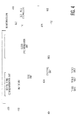
- Fig. 5 depicts an embodiment of the slot table address system 168, 368 or 468 depicted in Fig. 1 , 3 or 4 .
- a slot table address system 568 includes a bit processing device 560, a bit masking device 562, a bit processing device 564 and a value setting device 558. At least one of the bit processing device 560, the bit masking device, the bit processing device 564 and the value setting device 558 may include hardware such as one or more processors and/or software stored in a non-transitory computer-readable medium such as one or more memory circuits.
- the slot table address system 568 can allow a seamless exchange between bits that are used to specify a slot counter and bits that are used to specify a communications cycle.
- the slot table address system 568 takes in three input values, which include a slot counter value "slot_counter_nxt,” a cycle counter value “cycle_counter_nxt,” and a configuration setting value “n_cycle_counter_bits,” and generates a slot table entry address.
- the slot counter value is inputted into the bit processing device 560
- the cycle counter value is inputted into the bit masking device 562
- the configuration setting value is inputted into the bit processing device 560 and the bit masking device 562.
- These three input values are generated by hardware such as dedicated logic, one or more processors and/or software stored in a non-transitory computer-readable medium such as one or more memory circuits.
- the state machines 342, 442 may generate these three input values.
- the slot table address system 568 keeps tracks of three input values from the external entities.
- the slot counter value identifies or represents a time slot (e.g., a current time slot) of data communications between the communications nodes 102-1, 102-2, 102-3, 102-4, 102-5, 102-6, 102-7, 102-8, 104, of the communications network 100.
- the slot counter value identifies or represents a time slot (e.g., a current time slot) of data communications between the communications nodes 102-1, 102-2, 102-3, 102-4, 102-5, 102-6, 102-7, 102-8, 104, of the communications network 100 through the communications controller 104, the switch 304 or the CBG 404.
- the cycle counter value identifies or represents a communications cycle containing the time slot.
- the generated slot table entry address is directly or indirectly used to locate a slot table entry of a slot table stored in the slot table storage unit 166, 366 or 466 depicted in Fig. 1 , 3 or 4 .
- the slot counter value has eleven bits
- the cycle counter value has seven bits
- the slot table address has up to seventeen bits.
- the configuration setting value specifies how many bits of the cycle counter value are used for the least significant bits in the slot table entry address.
- the remainder of the slot table entry address may be formed by performing a logically OR action on the appropriate number of shifted slot counter bits.
- the bit processing device 560 of the slot table address system 568 is configured to process the slot counter value according to the configuration setting value to produce a processed slot counter value.
- the bit processing device 560 is a bit shifting device configured to shift the slot counter value according to the configuration setting value to produce a shifted slot counter value.
- the bit shifting device is further configured to shift the slot counter value in the direction from least significant bits to most significant bits according to the configuration setting value to produce the shifted slot counter value.
- the bit shifting device is further configured to shift the slot counter value left according to the configuration setting value to produce the shifted slot counter value.
- the operation of shift-left is mathematically equivalent to a multiplication by the appropriate power of two.
- the bit processing device 560 can perform a shift operation such as shift-left operation, a mathematically equivalent multiplication operation, and any combination of a shift operation and a multiplication operation to produce the desired result.
- the bit masking device 562 of the slot table address system 568 is configured to mask the cycle counter value according to the configuration setting value to generate a masked cycle counter value.
- the bit processing device 560 and the bit masking device operate according to the same configuration setting value in the embodiment depicted in Fig. 5 , in some other embodiment, the bit processing device 560 and the bit masking device may operate according to different configuration setting values.
- the bit processing device 564 of the slot table address system 568 is configured to process the processed slot counter value (e.g., shifted slot counter value) from the bit processing device 560 and the masked cycle counter value from the bit masking device to generate a slot table entry address.
- the bit processing device 564 is an OR logic circuit configured to perform an logic OR operation on the processed (e.g., shifted) slot counter value from the bit processing device 560 and the masked cycle counter value from the bit masking device to generate a slot table entry address.
- the logical-OR operation is mathematically equivalent to an addition operation.
- the logical OR operation is mathematically equivalent to an addition as there is no risk of a carry overflow when adding the least significant bits together since one of the operand is zero.
- the bit processing device 564 can perform a logical OR operation, a mathematically equivalent addition operation, and any combination of a logical OR operation and an addition operation to produce the desired result.
- the slot table address system 568 that combines the "shift left" and "logical-OR" operations is the most area efficient.
- the slot table address system 568 also includes a value setting device 558 configured to set the configuration setting value such that the number of bits of the slot counter value that are used in a slot table entry address and the number of bits of the cycle counter value that are used in the slot table entry address are specified.
- the value setting device may contain an interface to set the configuration setting value.
- the value setting device is further configured to set the configuration setting value such that the number of bits of the cycle counter value that are used for least significant bits in the slot table entry address is.
- the value setting device may be optional.
- a device or an end-user directly supplies a configuration setting value to the slot table address system 568.
- a slot table entry address is generated by combining a slot counter value that is logical shifted left with a masked version of a cycle counter value.
- the most-significant bits in the cycle counter value are not used to generate the slot table entry address. Therefore, the most-significant bits in the cycle counter value do not affect the resulting slot table entry address.
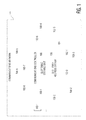
- Figs. 6 and 7 show some examples of slot counter values, cycle counter values, and slot table addresses derived using the slot counter values and the cycle counter values.
- the configuration setting value is 2
- the slot counter values are shifted left by 2
- Slot table addresses, slot counter values, and cycle counter values shown in Fig. 6 satisfy:
- slot_table_address (slot_counter_nxt ⁇ 3) OR (cycle_counter_nxt AND 7), where "slot_table_address” represents a slot table address, "slot_counter_nxt” represents a slot counter value, and "cycle_counter_nxt” represents a cycle counter value.
- the masking operation performed by the bit masking device 562 is an AND operation.
- the slot table address for cycle count 0 and slot count 2 in Fig. 7 is the same as the slot table address for cycle count 0 and slot count 4 and the slot table address for cycle count 4 and slot count 4 in Fig. 6 .
- the slot table address "16" is reused in the different use cases from different cycle/slot count combinations, depending on the configuration setting value.
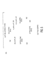
- Fig. 8 is a process flow diagram of a method for generating a slot table entry address for a communications device of a communications network to access a slot table in accordance with an embodiment of the invention.
- the communications controller may be similar to or same as the communications controller 104 depicted in Fig. 1 , the switch 304 depicted in Fig. 3 , and the CBG 404 depicted in Fig. 4 .
- a slot counter value is processed according to a configuration setting value to produce a processed slot counter value, where the slot counter value identifies a time slot of data communications of the communications network.
- a cycle counter value is masked according to the configuration setting value to generate a masked cycle counter value, where the cycle counter value identifies a communications cycle containing the time slot.
- the processed slot counter value and the masked cycle counter value are processed to generate a slot table entry address such that a corresponding slot table entry of the time slot of the communications cycle in a slot table is accessed by the communications device at the slot table entry address.
- the various components or units of the embodiments that have been described or depicted may be implemented in hardware, software that is stored in a non-transitory computer readable medium or a combination of hardware and software that is stored in a non-transitory computer readable medium.
- the non-transitory computer readable medium can be an electronic, magnetic, optical, electromagnetic, infrared, or semiconductor system (or apparatus or device), or a propagation medium.
- Examples of a non-transitory computer-readable medium include a semiconductor or solid state memory, magnetic tape, a removable computer diskette, a random access memory (RAM), a read-only memory (ROM), a rigid magnetic disk, and an optical disk.
- Current examples of optical disks include a compact disk with read only memory (CD-ROM), a compact disk with read/write (CD-R/W), a digital video disk (DVD), and a Blu-ray disk.
- the various components or units of the embodiments may be implemented in a processor, which may include a multifunction processor and/or an application-specific processor .
Landscapes
- Engineering & Computer Science (AREA)
- Computer Networks & Wireless Communication (AREA)
- Signal Processing (AREA)
- Small-Scale Networks (AREA)
Applications Claiming Priority (1)
| Application Number | Priority Date | Filing Date | Title |
|---|---|---|---|
| US13/239,151 US8798090B2 (en) | 2011-09-21 | 2011-09-21 | System and method for creating a slot table entry address for a communications device |
Publications (2)
| Publication Number | Publication Date |
|---|---|
| EP2573672A1 true EP2573672A1 (fr) | 2013-03-27 |
| EP2573672B1 EP2573672B1 (fr) | 2016-10-12 |
Family
ID=47148582
Family Applications (1)
| Application Number | Title | Priority Date | Filing Date |
|---|---|---|---|
| EP12181625.0A Active EP2573672B1 (fr) | 2011-09-21 | 2012-08-24 | Système et procédé pour générer une adresse d'entrée de table de fente pour un dispositif de communications |
Country Status (3)
| Country | Link |
|---|---|
| US (1) | US8798090B2 (fr) |
| EP (1) | EP2573672B1 (fr) |
| CN (1) | CN103024093A (fr) |
Cited By (1)
| Publication number | Priority date | Publication date | Assignee | Title |
|---|---|---|---|---|
| EP3817302A1 (fr) * | 2019-11-04 | 2021-05-05 | Vodafone IP Licensing Limited | Procédés et appareil d'échange de données dans un réseau de télécommunications mobile |
Families Citing this family (7)
| Publication number | Priority date | Publication date | Assignee | Title |
|---|---|---|---|---|
| JP4978757B1 (ja) * | 2012-01-24 | 2012-07-18 | オムロン株式会社 | データ設定装置 |
| US9641455B2 (en) | 2013-07-18 | 2017-05-02 | International Business Machines Corporation | Mechanism for terminating relay operations in a distributed switch with cascaded configuration |
| US10389553B2 (en) * | 2013-10-29 | 2019-08-20 | Eaton Intelligent Power Limited | Communication bridge between bus networks |
| US10616914B2 (en) | 2017-01-06 | 2020-04-07 | Qualcomm Incorporated | Unicast data transmission on a downlink common burst of a slot using mini-slots |
| CN106603364B (zh) * | 2017-01-06 | 2019-11-01 | 上海理工大学 | 一种可用于实时传输的以太网通信方法 |
| JP7211889B2 (ja) * | 2019-05-13 | 2023-01-24 | 日立Astemo株式会社 | 車両制御装置、及び、車両制御システム |
| CN115733849B (zh) * | 2021-08-27 | 2025-12-16 | 北京车和家信息技术有限公司 | 电子控制单元的刷写方法、装置、系统、设备和存储介质 |
Citations (2)
| Publication number | Priority date | Publication date | Assignee | Title |
|---|---|---|---|---|
| WO2009063347A1 (fr) * | 2007-11-14 | 2009-05-22 | Nxp B.V. | Système flexray à stockage efficace des instructions |
| US20090175290A1 (en) * | 2005-07-21 | 2009-07-09 | Josef Newald | Flexray communications module, flexray communications controller, and method for transmitting messages between a flexray communications link and a flexray participant |
Family Cites Families (4)
| Publication number | Priority date | Publication date | Assignee | Title |
|---|---|---|---|---|
| DE10329179A1 (de) * | 2003-06-30 | 2005-03-17 | Volkswagen Ag | Anordnung und Verfahren zur Verwaltung eines Speichers |
| JP4401239B2 (ja) * | 2004-05-12 | 2010-01-20 | Necエレクトロニクス株式会社 | 通信メッセージ変換装置、通信方法及び通信システム |
| AT501480B8 (de) * | 2004-09-15 | 2007-02-15 | Tttech Computertechnik Ag | Verfahren zum erstellen von kommunikationsplänen für ein verteiltes echtzeit-computersystem |
| AT507125B1 (de) * | 2008-07-25 | 2010-05-15 | Tttech Computertechnik Ag | Multirouter für zeitgesteuerte kommunikationssysteme |
-
2011
- 2011-09-21 US US13/239,151 patent/US8798090B2/en active Active
-
2012
- 2012-08-24 EP EP12181625.0A patent/EP2573672B1/fr active Active
- 2012-09-19 CN CN2012103508420A patent/CN103024093A/zh active Pending
Patent Citations (2)
| Publication number | Priority date | Publication date | Assignee | Title |
|---|---|---|---|---|
| US20090175290A1 (en) * | 2005-07-21 | 2009-07-09 | Josef Newald | Flexray communications module, flexray communications controller, and method for transmitting messages between a flexray communications link and a flexray participant |
| WO2009063347A1 (fr) * | 2007-11-14 | 2009-05-22 | Nxp B.V. | Système flexray à stockage efficace des instructions |
Non-Patent Citations (1)
| Title |
|---|
| FLEXRAY CONSORTIUM: "FlexRay Communications System Protocol Specification V 2.1 Revision A", INTERNET CITATION, 15 December 2005 (2005-12-15), pages 1 - 245, XP002521572 * |
Cited By (2)
| Publication number | Priority date | Publication date | Assignee | Title |
|---|---|---|---|---|
| EP3817302A1 (fr) * | 2019-11-04 | 2021-05-05 | Vodafone IP Licensing Limited | Procédés et appareil d'échange de données dans un réseau de télécommunications mobile |
| WO2021089572A1 (fr) * | 2019-11-04 | 2021-05-14 | Vodafone Ip Licensing Limited | Procédé et appareil d'échange de données dans un réseau de télécommunications mobile |
Also Published As
| Publication number | Publication date |
|---|---|
| US20130070783A1 (en) | 2013-03-21 |
| US8798090B2 (en) | 2014-08-05 |
| CN103024093A (zh) | 2013-04-03 |
| EP2573672B1 (fr) | 2016-10-12 |
Similar Documents
| Publication | Publication Date | Title |
|---|---|---|
| EP2573672B1 (fr) | Système et procédé pour générer une adresse d'entrée de table de fente pour un dispositif de communications | |
| EP2584741A1 (fr) | Gardien de bus central (CBG) et procédé pour faire fonctionner le CBG | |
| US8885645B2 (en) | Method for transmitting data | |
| US8861370B2 (en) | System and method for testing a communications network having a central bus guardian (CBG) to detect a faulty condition associated with the CBG | |
| JP7030742B2 (ja) | 通信システム、および通信制御方法 | |
| Shaw et al. | An introduction to FlexRay as an industrial network | |
| Talbot et al. | Comparision of fieldbus systems can, ttcan, flexray and lin in passenger vehicles | |
| US9645958B2 (en) | Method and device for transmitting data having a variable bit length | |
| US9432488B2 (en) | High speed embedded protocol for distributed control systems | |
| EP1687943A1 (fr) | Agregation en cliques dans des reseaux amrt | |
| RU2678715C2 (ru) | Протокол передачи данных с состоянием исключения протокола | |
| US11063868B2 (en) | Operation method of a communication node in network | |
| EP2573981A2 (fr) | Système et procédé pour coder une fente table pour un contrôleur de communications | |
| JP6410914B1 (ja) | シリアル通信システム | |
| Kimm et al. | Integrated fault tolerant system for automotive bus networks | |
| US20130013127A1 (en) | Network interface for use in vehicles | |
| Sharma | In-Vehicular Communication Networking Protocol | |
| An et al. | Analysis of CAN FD to CAN message routing method for CAN FD and CAN gateway | |
| Ravichandran et al. | Design and development of can and flex ray protocols for real-time systems | |
| Lawrenz | CAN Basic Architectures | |
| Kim et al. | A method for improving the reliability of the gateway system by using OSEK and duplication scheme | |
| Johansson | Evaluation of Communication Interfaces for ElectronicControl Units in Heavy-duty Vehicles | |
| Wang et al. | Design and quantitative evaluation of a novel FlexRay Bus Guardian | |
| Mahmud | Various Emerging Time-Triggered Protocols for Drive-by-Wire Applications | |
| Coppolino | Dependability aspects of automotive x-by-wire technologies |
Legal Events
| Date | Code | Title | Description |
|---|---|---|---|
| PUAI | Public reference made under article 153(3) epc to a published international application that has entered the european phase |
Free format text: ORIGINAL CODE: 0009012 |
|
| AK | Designated contracting states |
Kind code of ref document: A1 Designated state(s): AL AT BE BG CH CY CZ DE DK EE ES FI FR GB GR HR HU IE IS IT LI LT LU LV MC MK MT NL NO PL PT RO RS SE SI SK SM TR |
|
| AX | Request for extension of the european patent |
Extension state: BA ME |
|
| 17P | Request for examination filed |
Effective date: 20130927 |
|
| RBV | Designated contracting states (corrected) |
Designated state(s): AL AT BE BG CH CY CZ DE DK EE ES FI FR GB GR HR HU IE IS IT LI LT LU LV MC MK MT NL NO PL PT RO RS SE SI SK SM TR |
|
| GRAP | Despatch of communication of intention to grant a patent |
Free format text: ORIGINAL CODE: EPIDOSNIGR1 |
|
| RIC1 | Information provided on ipc code assigned before grant |
Ipc: H04L 12/863 20130101ALI20160331BHEP Ipc: G06F 9/00 20060101AFI20160331BHEP Ipc: H04L 12/403 20060101ALI20160331BHEP Ipc: H04L 12/40 20060101ALI20160331BHEP |
|
| INTG | Intention to grant announced |
Effective date: 20160429 |
|
| RAP1 | Party data changed (applicant data changed or rights of an application transferred) |
Owner name: NXP B.V. |
|
| GRAS | Grant fee paid |
Free format text: ORIGINAL CODE: EPIDOSNIGR3 |
|
| GRAA | (expected) grant |
Free format text: ORIGINAL CODE: 0009210 |
|
| AK | Designated contracting states |
Kind code of ref document: B1 Designated state(s): AL AT BE BG CH CY CZ DE DK EE ES FI FR GB GR HR HU IE IS IT LI LT LU LV MC MK MT NL NO PL PT RO RS SE SI SK SM TR |
|
| REG | Reference to a national code |
Ref country code: GB Ref legal event code: FG4D |
|
| REG | Reference to a national code |
Ref country code: CH Ref legal event code: EP |
|
| REG | Reference to a national code |
Ref country code: AT Ref legal event code: REF Ref document number: 837073 Country of ref document: AT Kind code of ref document: T Effective date: 20161015 |
|
| REG | Reference to a national code |
Ref country code: IE Ref legal event code: FG4D |
|
| REG | Reference to a national code |
Ref country code: DE Ref legal event code: R096 Ref document number: 602012023970 Country of ref document: DE |
|
| REG | Reference to a national code |
Ref country code: LT Ref legal event code: MG4D |
|
| REG | Reference to a national code |
Ref country code: NL Ref legal event code: MP Effective date: 20161012 |
|
| PG25 | Lapsed in a contracting state [announced via postgrant information from national office to epo] |
Ref country code: LV Free format text: LAPSE BECAUSE OF FAILURE TO SUBMIT A TRANSLATION OF THE DESCRIPTION OR TO PAY THE FEE WITHIN THE PRESCRIBED TIME-LIMIT Effective date: 20161012 |
|
| REG | Reference to a national code |
Ref country code: AT Ref legal event code: MK05 Ref document number: 837073 Country of ref document: AT Kind code of ref document: T Effective date: 20161012 |
|
| PG25 | Lapsed in a contracting state [announced via postgrant information from national office to epo] |
Ref country code: GR Free format text: LAPSE BECAUSE OF FAILURE TO SUBMIT A TRANSLATION OF THE DESCRIPTION OR TO PAY THE FEE WITHIN THE PRESCRIBED TIME-LIMIT Effective date: 20170113 Ref country code: LT Free format text: LAPSE BECAUSE OF FAILURE TO SUBMIT A TRANSLATION OF THE DESCRIPTION OR TO PAY THE FEE WITHIN THE PRESCRIBED TIME-LIMIT Effective date: 20161012 Ref country code: SE Free format text: LAPSE BECAUSE OF FAILURE TO SUBMIT A TRANSLATION OF THE DESCRIPTION OR TO PAY THE FEE WITHIN THE PRESCRIBED TIME-LIMIT Effective date: 20161012 Ref country code: NO Free format text: LAPSE BECAUSE OF FAILURE TO SUBMIT A TRANSLATION OF THE DESCRIPTION OR TO PAY THE FEE WITHIN THE PRESCRIBED TIME-LIMIT Effective date: 20170112 |
|
| PG25 | Lapsed in a contracting state [announced via postgrant information from national office to epo] |
Ref country code: PT Free format text: LAPSE BECAUSE OF FAILURE TO SUBMIT A TRANSLATION OF THE DESCRIPTION OR TO PAY THE FEE WITHIN THE PRESCRIBED TIME-LIMIT Effective date: 20170213 Ref country code: RS Free format text: LAPSE BECAUSE OF FAILURE TO SUBMIT A TRANSLATION OF THE DESCRIPTION OR TO PAY THE FEE WITHIN THE PRESCRIBED TIME-LIMIT Effective date: 20161012 Ref country code: AT Free format text: LAPSE BECAUSE OF FAILURE TO SUBMIT A TRANSLATION OF THE DESCRIPTION OR TO PAY THE FEE WITHIN THE PRESCRIBED TIME-LIMIT Effective date: 20161012 Ref country code: HR Free format text: LAPSE BECAUSE OF FAILURE TO SUBMIT A TRANSLATION OF THE DESCRIPTION OR TO PAY THE FEE WITHIN THE PRESCRIBED TIME-LIMIT Effective date: 20161012 Ref country code: NL Free format text: LAPSE BECAUSE OF FAILURE TO SUBMIT A TRANSLATION OF THE DESCRIPTION OR TO PAY THE FEE WITHIN THE PRESCRIBED TIME-LIMIT Effective date: 20161012 Ref country code: BE Free format text: LAPSE BECAUSE OF FAILURE TO SUBMIT A TRANSLATION OF THE DESCRIPTION OR TO PAY THE FEE WITHIN THE PRESCRIBED TIME-LIMIT Effective date: 20161012 Ref country code: IS Free format text: LAPSE BECAUSE OF FAILURE TO SUBMIT A TRANSLATION OF THE DESCRIPTION OR TO PAY THE FEE WITHIN THE PRESCRIBED TIME-LIMIT Effective date: 20170212 Ref country code: ES Free format text: LAPSE BECAUSE OF FAILURE TO SUBMIT A TRANSLATION OF THE DESCRIPTION OR TO PAY THE FEE WITHIN THE PRESCRIBED TIME-LIMIT Effective date: 20161012 Ref country code: PL Free format text: LAPSE BECAUSE OF FAILURE TO SUBMIT A TRANSLATION OF THE DESCRIPTION OR TO PAY THE FEE WITHIN THE PRESCRIBED TIME-LIMIT Effective date: 20161012 Ref country code: FI Free format text: LAPSE BECAUSE OF FAILURE TO SUBMIT A TRANSLATION OF THE DESCRIPTION OR TO PAY THE FEE WITHIN THE PRESCRIBED TIME-LIMIT Effective date: 20161012 |
|
| REG | Reference to a national code |
Ref country code: DE Ref legal event code: R097 Ref document number: 602012023970 Country of ref document: DE |
|
| PG25 | Lapsed in a contracting state [announced via postgrant information from national office to epo] |
Ref country code: CZ Free format text: LAPSE BECAUSE OF FAILURE TO SUBMIT A TRANSLATION OF THE DESCRIPTION OR TO PAY THE FEE WITHIN THE PRESCRIBED TIME-LIMIT Effective date: 20161012 Ref country code: SK Free format text: LAPSE BECAUSE OF FAILURE TO SUBMIT A TRANSLATION OF THE DESCRIPTION OR TO PAY THE FEE WITHIN THE PRESCRIBED TIME-LIMIT Effective date: 20161012 Ref country code: EE Free format text: LAPSE BECAUSE OF FAILURE TO SUBMIT A TRANSLATION OF THE DESCRIPTION OR TO PAY THE FEE WITHIN THE PRESCRIBED TIME-LIMIT Effective date: 20161012 Ref country code: RO Free format text: LAPSE BECAUSE OF FAILURE TO SUBMIT A TRANSLATION OF THE DESCRIPTION OR TO PAY THE FEE WITHIN THE PRESCRIBED TIME-LIMIT Effective date: 20161012 Ref country code: DK Free format text: LAPSE BECAUSE OF FAILURE TO SUBMIT A TRANSLATION OF THE DESCRIPTION OR TO PAY THE FEE WITHIN THE PRESCRIBED TIME-LIMIT Effective date: 20161012 |
|
| PLBE | No opposition filed within time limit |
Free format text: ORIGINAL CODE: 0009261 |
|
| STAA | Information on the status of an ep patent application or granted ep patent |
Free format text: STATUS: NO OPPOSITION FILED WITHIN TIME LIMIT |
|
| PG25 | Lapsed in a contracting state [announced via postgrant information from national office to epo] |
Ref country code: IT Free format text: LAPSE BECAUSE OF FAILURE TO SUBMIT A TRANSLATION OF THE DESCRIPTION OR TO PAY THE FEE WITHIN THE PRESCRIBED TIME-LIMIT Effective date: 20161012 Ref country code: BG Free format text: LAPSE BECAUSE OF FAILURE TO SUBMIT A TRANSLATION OF THE DESCRIPTION OR TO PAY THE FEE WITHIN THE PRESCRIBED TIME-LIMIT Effective date: 20170112 Ref country code: SM Free format text: LAPSE BECAUSE OF FAILURE TO SUBMIT A TRANSLATION OF THE DESCRIPTION OR TO PAY THE FEE WITHIN THE PRESCRIBED TIME-LIMIT Effective date: 20161012 |
|
| 26N | No opposition filed |
Effective date: 20170713 |
|
| PG25 | Lapsed in a contracting state [announced via postgrant information from national office to epo] |
Ref country code: SI Free format text: LAPSE BECAUSE OF FAILURE TO SUBMIT A TRANSLATION OF THE DESCRIPTION OR TO PAY THE FEE WITHIN THE PRESCRIBED TIME-LIMIT Effective date: 20161012 |
|
| REG | Reference to a national code |
Ref country code: CH Ref legal event code: PL |
|
| PG25 | Lapsed in a contracting state [announced via postgrant information from national office to epo] |
Ref country code: MC Free format text: LAPSE BECAUSE OF FAILURE TO SUBMIT A TRANSLATION OF THE DESCRIPTION OR TO PAY THE FEE WITHIN THE PRESCRIBED TIME-LIMIT Effective date: 20161012 |
|
| GBPC | Gb: european patent ceased through non-payment of renewal fee |
Effective date: 20170824 |
|
| PG25 | Lapsed in a contracting state [announced via postgrant information from national office to epo] |
Ref country code: LI Free format text: LAPSE BECAUSE OF NON-PAYMENT OF DUE FEES Effective date: 20170831 Ref country code: CH Free format text: LAPSE BECAUSE OF NON-PAYMENT OF DUE FEES Effective date: 20170831 |
|
| REG | Reference to a national code |
Ref country code: FR Ref legal event code: ST Effective date: 20180430 |
|
| REG | Reference to a national code |
Ref country code: IE Ref legal event code: MM4A |
|
| PG25 | Lapsed in a contracting state [announced via postgrant information from national office to epo] |
Ref country code: LU Free format text: LAPSE BECAUSE OF NON-PAYMENT OF DUE FEES Effective date: 20170824 |
|
| PG25 | Lapsed in a contracting state [announced via postgrant information from national office to epo] |
Ref country code: GB Free format text: LAPSE BECAUSE OF NON-PAYMENT OF DUE FEES Effective date: 20170824 Ref country code: IE Free format text: LAPSE BECAUSE OF NON-PAYMENT OF DUE FEES Effective date: 20170824 |
|
| PG25 | Lapsed in a contracting state [announced via postgrant information from national office to epo] |
Ref country code: FR Free format text: LAPSE BECAUSE OF NON-PAYMENT OF DUE FEES Effective date: 20170831 |
|
| PG25 | Lapsed in a contracting state [announced via postgrant information from national office to epo] |
Ref country code: MT Free format text: LAPSE BECAUSE OF NON-PAYMENT OF DUE FEES Effective date: 20170824 |
|
| PG25 | Lapsed in a contracting state [announced via postgrant information from national office to epo] |
Ref country code: HU Free format text: LAPSE BECAUSE OF FAILURE TO SUBMIT A TRANSLATION OF THE DESCRIPTION OR TO PAY THE FEE WITHIN THE PRESCRIBED TIME-LIMIT; INVALID AB INITIO Effective date: 20120824 |
|
| PG25 | Lapsed in a contracting state [announced via postgrant information from national office to epo] |
Ref country code: CY Free format text: LAPSE BECAUSE OF NON-PAYMENT OF DUE FEES Effective date: 20161012 |
|
| PG25 | Lapsed in a contracting state [announced via postgrant information from national office to epo] |
Ref country code: MK Free format text: LAPSE BECAUSE OF FAILURE TO SUBMIT A TRANSLATION OF THE DESCRIPTION OR TO PAY THE FEE WITHIN THE PRESCRIBED TIME-LIMIT Effective date: 20161012 |
|
| PG25 | Lapsed in a contracting state [announced via postgrant information from national office to epo] |
Ref country code: TR Free format text: LAPSE BECAUSE OF FAILURE TO SUBMIT A TRANSLATION OF THE DESCRIPTION OR TO PAY THE FEE WITHIN THE PRESCRIBED TIME-LIMIT Effective date: 20161012 |
|
| PG25 | Lapsed in a contracting state [announced via postgrant information from national office to epo] |
Ref country code: AL Free format text: LAPSE BECAUSE OF FAILURE TO SUBMIT A TRANSLATION OF THE DESCRIPTION OR TO PAY THE FEE WITHIN THE PRESCRIBED TIME-LIMIT Effective date: 20161012 |
|
| P01 | Opt-out of the competence of the unified patent court (upc) registered |
Effective date: 20230725 |
|
| PGFP | Annual fee paid to national office [announced via postgrant information from national office to epo] |
Ref country code: DE Payment date: 20250724 Year of fee payment: 14 |