EP2573713A2 - Bildverarbeitungsvorrichtung, Verfahren und Programm - Google Patents
Bildverarbeitungsvorrichtung, Verfahren und Programm Download PDFInfo
- Publication number
- EP2573713A2 EP2573713A2 EP20120185805 EP12185805A EP2573713A2 EP 2573713 A2 EP2573713 A2 EP 2573713A2 EP 20120185805 EP20120185805 EP 20120185805 EP 12185805 A EP12185805 A EP 12185805A EP 2573713 A2 EP2573713 A2 EP 2573713A2
- Authority
- EP
- European Patent Office
- Prior art keywords
- candidate
- model
- points
- candidate points
- mapped
- Prior art date
- Legal status (The legal status is an assumption and is not a legal conclusion. Google has not performed a legal analysis and makes no representation as to the accuracy of the status listed.)
- Withdrawn
Links
Images




Classifications
-
- G—PHYSICS
- G06—COMPUTING OR CALCULATING; COUNTING
- G06T—IMAGE DATA PROCESSING OR GENERATION, IN GENERAL
- G06T7/00—Image analysis
- G06T7/10—Segmentation; Edge detection
- G06T7/149—Segmentation; Edge detection involving deformable models, e.g. active contour models
-
- G—PHYSICS
- G06—COMPUTING OR CALCULATING; COUNTING
- G06T—IMAGE DATA PROCESSING OR GENERATION, IN GENERAL
- G06T7/00—Image analysis
- G06T7/10—Segmentation; Edge detection
- G06T7/162—Segmentation; Edge detection involving graph-based methods
-
- G—PHYSICS
- G06—COMPUTING OR CALCULATING; COUNTING
- G06V—IMAGE OR VIDEO RECOGNITION OR UNDERSTANDING
- G06V10/00—Arrangements for image or video recognition or understanding
- G06V10/70—Arrangements for image or video recognition or understanding using pattern recognition or machine learning
- G06V10/74—Image or video pattern matching; Proximity measures in feature spaces
- G06V10/75—Organisation of the matching processes, e.g. simultaneous or sequential comparisons of image or video features; Coarse-fine approaches, e.g. multi-scale approaches; using context analysis; Selection of dictionaries
- G06V10/757—Matching configurations of points or features
-
- G—PHYSICS
- G06—COMPUTING OR CALCULATING; COUNTING
- G06T—IMAGE DATA PROCESSING OR GENERATION, IN GENERAL
- G06T2207/00—Indexing scheme for image analysis or image enhancement
- G06T2207/20—Special algorithmic details
- G06T2207/20072—Graph-based image processing
-
- G—PHYSICS
- G06—COMPUTING OR CALCULATING; COUNTING
- G06T—IMAGE DATA PROCESSING OR GENERATION, IN GENERAL
- G06T2207/00—Indexing scheme for image analysis or image enhancement
- G06T2207/20—Special algorithmic details
- G06T2207/20112—Image segmentation details
- G06T2207/20164—Salient point detection; Corner detection
-
- G—PHYSICS
- G06—COMPUTING OR CALCULATING; COUNTING
- G06T—IMAGE DATA PROCESSING OR GENERATION, IN GENERAL
- G06T2207/00—Indexing scheme for image analysis or image enhancement
- G06T2207/30—Subject of image; Context of image processing
- G06T2207/30004—Biomedical image processing
- G06T2207/30101—Blood vessel; Artery; Vein; Vascular
-
- G—PHYSICS
- G06—COMPUTING OR CALCULATING; COUNTING
- G06T—IMAGE DATA PROCESSING OR GENERATION, IN GENERAL
- G06T2207/00—Indexing scheme for image analysis or image enhancement
- G06T2207/30—Subject of image; Context of image processing
- G06T2207/30172—Centreline of tubular or elongated structure
-
- G—PHYSICS
- G06—COMPUTING OR CALCULATING; COUNTING
- G06V—IMAGE OR VIDEO RECOGNITION OR UNDERSTANDING
- G06V2201/00—Indexing scheme relating to image or video recognition or understanding
- G06V2201/03—Recognition of patterns in medical or anatomical images
- G06V2201/031—Recognition of patterns in medical or anatomical images of internal organs
Definitions
- the present invention relates to an image processing device, an image processing method and an image processing program for extracting a plurality of candidate points belonging to a predetermined structure from image data and performing matching between the candidate points and nodes of a known shape model which represents a shape of the predetermined structure.
- Patent Document 1 discloses extracting a plurality of candidate points forming coronary arteries based on values of voxel data forming volume data, selecting, from the extracted candidate points, a corresponding point corresponding to each model label forming a shape model such that the corresponding points form a graph structure that is most similar to the shape model, and determining paths connecting the selected corresponding points by selectively connecting the candidate points to achieve a minimal cost based on a predetermined index value.
- the selection of the corresponding points is achieved by providing an evaluation function for evaluating a similarity between the graph structure formed by the set of candidate points corresponding to the model labels and the shape model, and finding an optimal solution (a mapping between the candidate points and the model labels) of the evaluation function.
- P represents a set of candidate points S p
- Q represents a set of model labels T q
- x SpTq is a binary variable indicating a mapping relationship between an arbitrary candidate point S p and an arbitrary model label T q and has a value of 1 if the candidate point S p is mapped with the model label T q or a value of 0 if the candidate point S p is not mapped with the model label T q
- x is a P ⁇ Q-dimensional vector with values of the variable x SpTq being the elements thereof.
- Equation (1) the constraints limiting the feasible solutions x are formed by two inequality expressions.
- the inequality expression on the left means that a sum of values of the variable x SpTq obtained between an arbitrary model label T q and each candidate point S p belonging to the set P is not more than 1. This means that each model label is mapped with only one of the candidate points or none of the candidate points.
- the inequality expression on the right means that a sum of values of the variable x SpTq obtained between an arbitrary candidate point S p and each model label T q belonging to the set Q is not more than 1. This means that each candidate point is mapped with only one of the model labels or none of the model labels.
- the candidate points S 11 , S 15 , S 17 and S 19 may be selected as the corresponding points forming a graph structure that matches or is most similar to a shape model M ref 1 formed by model labels T 11 to T 14 , and a graph structure M s 1 may be formed by connecting the corresponding points.
- the candidate point selected to be mapped with the model label T 12 which is located at the branch point of the structure, is inappropriate, resulting in partially overlapped paths connecting the corresponding points.
- the candidate points S 21 , S 26 and S 27 may be selected as the corresponding points forming a graph structure that matches or is most similar to a shape model M ref 2 formed by model labels T 21 to T 23 , and a graph structure M s 2 may be formed by connecting the corresponding points.
- the candidate point selected to be mapped with the model label T 21 which is located at a branch point of the structure, is inappropriate, resulting in overlapped paths connecting the corresponding points.
- the present invention is directed to providing an image processing device, an image processing method and an image processing program that can achieve more accurate mapping between candidate points extracted from image data and nodes of a shape model.
- An aspect of the image processing device of the invention includes: candidate point extracting means for extracting a plurality of candidate points belonging to a predetermined structure from image data; shape model storing means storing a shape model representing a known shape of the predetermined structure, the shape model being formed by a plurality of model labels having a predetermined connection relationship; and corresponding point selecting means for selecting corresponding points corresponding to the model labels from the candidate points extracted by the candidate point extracting means under constraints (a) to (c) below: (a) each model label is mapped with only one of the candidate points or none of the candidate points; (b) each candidate point is mapped with only one of the model labels or none of the model labels; and (c) when a path between two candidate points which are mapped with each pair of the model labels connected with each other is determined, each candidate point which is mapped with none of the model labels is included in only one of the determined paths or none of the determined paths.
- An aspect of the image processing method of the invention includes the steps of: extracting a plurality of candidate points belonging to a predetermined structure from image data; obtaining a shape model stored in advance in shape model storing means, the shape model representing a known shape of the predetermined structure and being formed by a plurality of model labels having a predetermined connection relationship; and selecting corresponding points corresponding to the model labels from the extracted candidate points under constraints (a) to (c) below: (a) each model label is mapped with only one of the candidate points or none of the candidate points; (b) each candidate point is mapped with only one of the model labels or none of the model labels; and (c) when a path between two candidate points which are mapped with each pair of the model labels connected with each other is determined, each candidate point which is mapped with none of the model labels is included in only one of the determined paths or none of the determined paths.
- An aspect of the image processing program of the invention is a program for causing at least one computer to carry out the above-described image processing method.
- This program is recorded on a recording medium, such as a CD-ROM or DVD, or in a storage of a server computer or a network storage in a downloadable state to be delivered to the user.
- the predetermined structure herein may be any object that can be represented by a graph structure formed by points and lines connecting the points, and may include, in particular, a tubular structure of a human body, such as the trachea, the intestines, the coronary arteries, the cerebral vessels, the pulmonary vessels, the hepatic vessels or the bronchial tubes, or a person's face.
- the image data herein may be medical image data taken, for example, with a CT device, MR device, ultrasonic device, PET-CT device, SPECT device, 4D-CT device, OCT device or X-ray imaging device (CR, DR), three-dimensional image data, such as volume data, or image data taken with a digital camera, etc.
- the shape model herein represents a known shape of a predetermined structure, or, in other words, a shape to be detected of the predetermined structure.
- the shape model represents a typical anatomical shape of the predetermined structure, or an anatomical shape of the predetermined structure in a normal state.
- the paths in the constraint (c) can be determined by selectively connecting the candidate points such that a minimal cost based on a predetermined index value is achieved.
- the corresponding points may be selected by selecting the mapping relationship from a set C of candidate solutions satisfying a constraint expressed by Equation (2) below:
- C x ⁇ 0 ⁇ 1 P ⁇ Q
- x SpTq (x Sp'Tq , x Sp"Tq ) is a binary variable indicating a mapping relationship between an arbitrary candidate point S p (S p' , S p" ) and an arbitrary model label T q and has a value of 1 if the candidate point is mapped with the model label or a value of 0 if the candidate point is not mapped with the model label
- y SpSp'Sp is a binary variable having a value of 1 if the candidate point S p is included in a path between other two candidate points S p' and S p" belonging to the set P or a value of 0 if the candidate point S p is not included in the path.
- Equation (2) the constraints limiting the feasible solutions x are formed by two inequality expressions.
- the left side of the inequality expression on the left means a sum of values of the variable x SpTq obtained between an arbitrary model label T q and each candidate point S p belonging to the set P
- the first term of the left side of the inequality expression on the right means a sum of values of the variable x SpTq obtained between an arbitrary candidate point S p and each model label T q belonging to the set Q.
- ⁇ x Sp'Tq which is the second term of the left side of the inequality expression on the right, means a sum of values of the variable x Sp'Tq obtained between the candidate point S p' and each model label T q belonging to the set Q
- ⁇ x Sp"Tq means a sum of values of the variable x Sp"Tq obtained between the candidate point S p" and each model label T q belonging to the set Q.
- the corresponding points may be selected by minimizing an energy function E expressed by Equation (3) below including the vector x as a variable using a Dual Decomposition method: E x
- ⁇ ⁇ a ⁇ R ⁇ a x a + ⁇ a ⁇ b ⁇ R ⁇ R ⁇ ab x a ⁇ x b
- a and b represent individual mappings between the candidate points and the model labels in the mapping relationship represented by the vector x
- b represents a different mapping from a mapping represented by a
- a and b are elements belonging to a set R and the set R is a subset of P ⁇ Q
- ⁇ a represents a cost of a mapping a ⁇ R
- ⁇ ab represents a cost of (a,b) ⁇ R ⁇ R, which is a combination of the mappings a and b.
- the extraction of the candidate points may be achieved by detecting a region having an image feature and/or a structural feature of the predetermined structure from the image data, and extracting the candidate points from the detected region.
- the selection of the corresponding points may be achieved by any method as long as the corresponding points that match or are most similar to the shape model are selected from the candidate points. For example, a set of corresponding points forming a graph structure that matches or is most similar to the shape model may be selected using graph matching.
- the shape model storing means may store an evaluation function, which is obtained through a learning process using training image data known to represent the predetermined structure and indicates a likelihood of the candidate points representing the shape model. In this case, the selection of the corresponding point is achieved using the evaluation function.
- the image processing device of the invention may further include structure detecting means for detecting the predetermined structure from the image data based on the corresponding points selected by the corresponding point selecting means and the determined paths between the corresponding points.
- the corresponding point selecting means may determine the paths by selectively connecting the candidate points to achieve a minimal cost based on a predetermined index value.
- a plurality of candidate points belonging to a predetermined structure are extracted from image data
- a shape model which is stored in advance in the shape model storing means, represents a known shape of the predetermined structure and is formed by a plurality of model labels having a predetermined connection relationship, is obtained, and corresponding points corresponding to the model labels are selected from the extracted candidate points under the above-described constraints (a) to (c). Therefore, a mapping between the candidate points and the model labels which has overlapped paths connecting the corresponding points, such as the graph structure M s 1 shown in FIG. 11A or the graph structure M s 2 shown in FIG. 12A , can be excluded, thereby achieving more accurate mapping between the candidate points extracted from the image data and the model labels (nodes) of the shape model than that achieved by the conventional method.
- mapping is selected from a set C of candidate solutions satisfying a constraint expressed by Equation (2) described above, a mapping between the candidate points and the model labels which has overlapped paths connecting the corresponding points can be excluded, thereby achieving more accurate mapping between the candidate points extracted from the image data and the model labels of the shape model.
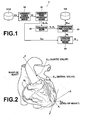
- FIG. 1 is a block diagram 1illustrating the schematic configuration of a structure detection device 1.
- the configuration of the structure detection device 1 as shown in FIG. 1 is implemented by executing, on a computer, a structure detection program, which is read in an auxiliary storage device of the computer.
- the structure detection program is distributed with being stored in a storage medium, such as a CD-ROM, or via a network, such as the Internet, to be installed on a computer.
- the structure detection device 1 shown in FIG. 1 detects a structure M, such as coronary arteries, from image data, and includes a candidate region detecting means 10, a candidate point extracting means 20, a normalizing means 30, a corresponding point selecting means 40 and a structure detecting means 50.
- the candidate region detecting means 10 detects a candidate region R c by determining whether or not each pixel in the image data DV forms a part of the predetermined structure M.
- the image data DV is stored in a data storing means VDB.
- the image data DV may be formed by a two-dimensional image or three-dimensional volume data generated from a plurality of two-dimensional images taken with an imaging device or a radiation detection device, for example.
- the candidate region detecting means 10 detects the candidate region using, for example, a technique disclosed in Japanese Patent Application No. 2009-048679 or a technique disclosed in Japanese Patent Application No. 2009-069895 , or any other known technique.
- a technique disclosed in Japanese Patent Application No. 2009-048679 or a technique disclosed in Japanese Patent Application No. 2009-069895 or any other known technique.
- the predetermined structure M is the coronary arteries of the heart, as shown in FIG. 2
- the candidate region R c is detected from volume data is described.
- the candidate region detecting means 10 calculates positions and major axis directions of candidate points forming central lines of the coronary arteries based on values of the voxel data forming the volume data DV.
- the candidate region detecting means 10 may calculate a Hessian matrix for the volume data DV, and analyze eigenvalues of the calculated Hessian matrix to calculate positional information and the major axis directions of the candidate points forming the central lines of the coronary arteries.
- the candidate region detecting means 10 calculates, for voxel data around the candidate points, feature quantities indicating likelihood of the voxel data representing the coronary arteries, and determines whether or not the voxel data represents the coronary artery region based on the calculated feature quantities.
- the determination based on the feature quantities may be achieved, for example, based on an evaluation function, which is obtained in advance through a machine learning process.
- image data DV which is determined to represent the coronary artery region, is extracted as the candidate region R c from the image data.
- FIG. 3 is a schematic diagram illustrating how the candidate points S p are extracted from the candidate region R c .
- the candidate point extracting means 20 extracts a plurality of (primary) candidate points S p0 from the candidate region R c , and connects the extracted (primary) candidate points S p0 .
- a minimal spanning tree algorithm may be used to connect all the (primary) candidate points S p0 at a minimal cost.
- the cost may be distances between the (primary) candidate points S p0 , or the like. In a case where the distances between the (primary) candidate points S p0 are used as the cost, such a definition may be made that, the larger the distances, the larger the cost. Then, the candidate point extracting means 20 divides the (primary) candidate points S p0 per a predetermined length unit (segmentation), and selects the dividing points, where the candidate points are divided, as (secondary) candidate points S p . Then, the candidate point extracting means 20 assigns a label S p to each (secondary) candidate point.
- the candidate point extracting means 20 selects the (secondary) candidate points S p from the (primary) candidate points S p0 is described as an example, a graph structure M s , which will be described later, may be detected using the (primary) candidate points S p0 .
- the candidate region detecting means 10 functions as the candidate point extracting means 20.
- the normalizing means 30 shown in FIG. 1 normalizes coordinates of the candidate points S p extracted by the candidate point extracting means 20 based on predetermined reference positions S ref .
- the predetermined structure is the coronary arteries
- the normalizing means 30 detects the aortic valve, the mitral valve and the apex of the heart, as shown in FIG. 2 , to set them as the reference positions S ref .
- the normalizing means 30 expresses the position of each candidate point S p in a new coordinate system, where the apex of the heart is the origin, an axis from the apex of the heart toward the aortic valve is a z-axis, an outer product of a vector from the apex of the heart toward the mitral valve and the z-axis is an x-axis, an outer product of the x-axis and the z-axis is a y-axis, and a length from the apex of the heart to the aortic valve is 1. Since the aortic valve, the mitral valve and the apex of the heart have small variation due to individual differences, using them as the reference positions S ref for the normalization can minimize variation of the candidate points S p due to individual differences.
- the corresponding point selecting means 40 shown in FIG. 1 forms the graph structure M s by selecting, from the candidate points S p normalized by normalizing means 30, corresponding points forming the graph structure M s that matches or is most similar to a shape model M ref stored in a shape model storing means DB, and connecting the selected corresponding points such that the graph structure M s substantially matches the shape model M ref .
- the corresponding point selecting means 40 selects the corresponding points forming a graph structure that matches or is most similar to the shape model M ref (i.e., the point S 2 for the label T 1 , the point S 4 for the label T 2 , the point S 6 for the label T 3 , and the point S 7 for the label T 4 ) to form the graph structure M s .
- the corresponding point selecting means 40 selects the corresponding points by using graph matching, and the shape model storing means DB stores an energy function E for graph matching as the shape model M ref . Then, the corresponding point selecting means 40 finds an optimal solution which achieves minimization of the energy function E from a set C' of candidate solutions that satisfy the constraint expressed by Equation (4) below:
- C ⁇ x ⁇ 0 ⁇ 1 P ⁇ Q
- P represents a set of candidate points S p
- Q represents a set of model labels T q
- x SpTq (x Sp'Tq , x Sp"Tq ) is a binary variable indicating a mapping relationship between an arbitrary candidate point S p (S p' , S p" ) and an arbitrary model label T q and has a value of 1 if the candidate point is mapped with the model label or a value of 0 if the candidate point is not mapped with the model label
- x is a P ⁇ Q-dimensional vector with values of the variable x SpTq being the elements thereof.
- Equation (4) the constraints limiting the feasible solutions x are formed by two inequality expressions.
- the inequality expression on the left means that a sum of values of the variable x SpTq obtained between an arbitrary model label T q and each candidate point S p belonging to the set P is not more than 1. This means that each model label is mapped with only one of the candidate points or none of the candidate points.
- the first term of the left side of the inequality expression on the right is a sum of values of the variable x SpTq obtained between an arbitrary candidate point S p and each model label T q belonging to the set Q, and has a value of 1 if the candidate point S p of interest is mapped with any of the model labels T q , or has a value of 0 if the candidate point S p of interest is not mapped with any of the model labels T q .
- the second term of the left side of the inequality expression on the right includes y SpSp'Sp" , ⁇ x sp'Tq and ⁇ x Sp"Tq .
- the variable y SpSp'Sp" is a binary variable. When a path between an arbitrary candidate point S p' and an arbitrary candidate point S p" is determined by selectively connecting candidate points which are mapped with none of the model labels to achieve a minimal cost based on a predetermined index value, the variable y SpSp'Sp" has a value of 1 if an arbitrary candidate point S p is selected to determine the path between the candidate points S p' and S p" , or a value of 0 if the candidate point S p of interest is not selected.
- the variable ⁇ x Sp'Tq is a sum of values of the variable x Sp'Tq obtained between the candidate point S p' and each model label T q belonging to the set Q, and has a value of 1 if the candidate point S p' is mapped with any of the model labels T q , or a value of 0 if the candidate point S p' is not mapped with any of the model labels T q .
- the variable ⁇ x Sp"Tq is a sum of values of the variable x Sp"Tq obtained between the candidate point S p" and each model label T q belonging to the set Q, and has a value of 1 if the candidate point S p" is mapped with any of the model labels T q , or a value of 0 if the candidate point S p" is not mapped with any of the model labels T q .
- the inequality expression on the right requires that the total sum of the first term and the second term is not more than 1, that is, one of the first term and the second term is 1 and the other is 0, or both the first term and the second term are 0. That is, when the first term has a value of 1, a solution where the second term has a value of 1 is excluded.
- each candidate point S p is mapped with only one of the model labels T q or none of the model labels T q , and that, when a path between two candidate points S p' and S p" which are mapped with the model labels is determined by selectively connecting the candidate points which are mapped with none the model labels to achieve a minimal cost based on a predetermined index value, each candidate point S p which is mapped with none of the model labels is included in only one of the determined paths or included in none of the determined paths.
- Equation (5) The energy function E is expressed by Equation (5) below, which includes the vector x as a variable: E x
- ⁇ ⁇ a ⁇ R ⁇ a x a + ⁇ a ⁇ b ⁇ R ⁇ R ⁇ ab x a ⁇ x b
- R represents a set of mappings between the candidate points and the model labels in the feasible solutions x
- the value of L Tq' (C Sp' ) is smaller as a distance between the coordinates of the candidate point S p' and the coordinates of the model label T q' is larger, and vice versa.
- the model labels T1 to T20 are extracted from the coronary arteries, which are the predetermined structure M
- the model labels T21 to T26 are extracted from the coronary veins.
- the shape model (graph) M ref is formed by connecting predetermined labels T q' among the model labels T1 to T26 by edges (lines). The extraction of the model labels T q is carried out for a plurality of pieces of training data.
- a sum of costs obtained by finding a path connecting each pair of S p' and S p" to achieve a minimal cost is used as the matching cost ⁇ ab .
- a different evaluation value relating to the found paths may be used as the matching cost.
- an evaluation value such as an average or variance of luminance values of pixels located along the paths, an average or variance of values of the radius of the structure M at each position along the paths, or the entire length of the paths, may be used.
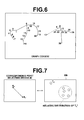
- (C Sp' - C Sp" ) is relative coordinates of the candidate point S p" relative to the coordinates of the candidate point S p' , and ⁇ Tq'Tq" and ⁇ Tq'Tq” 2 are an average value and a variance, respectively, of relative coordinates of the model label T q" relative to the coordinates of the model label T q' obtained from a plurality of pieces of training data which are known to represent the predetermined structure M (see FIG. 7 ).
- e local in the second term of Equation (8) represents a cost of a connection between directly-connected two candidate points S i , S j , if any, which are located along a path connecting the candidate points S p' and S p" mapped with the model labels, may be defined such that e local has a smaller value as the distance between the two points S i , S j is smaller, or the difference of the luminance value between the two points S i , S j is smaller, or the difference of the width of the blood vessel between the two points S i , S j is smaller, for example.
- ⁇ e local is a sum of values of the e local obtained for all the pairs of directly-connected two candidate points along the path between the candidate points S p' and S p"
- min ⁇ e local is found by calculating an optimal path between the candidate points S p' and S p" using, for example, an Dij kstra' s algorithm with handling the candidate points as a graph structure where each side (edge) connecting the candidate points is weighted with a weight defined by the e local .
- the corresponding point selecting means 40 stores paths connecting the candidate points between the candidate points S p' and S p" which achieve a minimal value of ⁇ e local in a predetermined memory area of the structure detection device 1. With this, an optimal path that smoothly connects the candidate points S p' and S p" via other candidate points is determined from paths connecting various candidate points between the candidate points S p' and S p" .
- the corresponding point selecting means 40 solves (i.e., finds an optimal solution of) the above-described minimization problem of the constrained energy function E using a Dual Decomposition (DD) method.
- the DD method divides a main problem to be solved into sub-problems that are calculable.
- a lower bound value is not larger than a solution (upper bound value) of the main problem, and therefore the minimal solution of the main problem is obtained when the lower bound value is the same value as the upper bound value.
- the division into the sub-problems is achieved as follows. For each node, one sub-problem that takes only the node and an adj acent node connected to the node by an edge into account is generated. Each sub-problem ignores the costs ⁇ a and ⁇ ab of the other nodes (i.e., considers the costs as "0").
- the solution thereof can be calculated by searching through all the combinations. If a branch-and-bound method is used, the solution can be obtained more rapidly. In the case where the branch-and-bound method is used, first, a relaxed lower bound is set. In this embodiment, the relaxed lower bound is defined as a minimal cost which may possibly be achieved by a certain node without a uniqueness constraint. By omitting detailed calculation of combinations which are not likely to improve the solution with referencing the relaxed lower bound, the amount of calculation can significantly be reduced.
- the corresponding point selecting means 40 may solve the minimization problem of the energy function E by using a loopy belief propagation method. Further, although the energy function E is minimized in Equation (5), the first variable term and the second variable term may be multiplied with a negative value, and the evaluation value of the energy function E may be maximized.
- the structure detecting means 50 shown in FIG. 1 detects the structure M based on the corresponding points selected by the corresponding point selecting means 40 and the optimal paths between the corresponding points determined in advance. It should be noted that the optimal paths have already been calculated and stored in a predetermined memory area of the structure detection device 1 when the corresponding point selecting means 40 calculates the min ⁇ e local .
- the structure detecting means 50 detects the entire structure M by using a minimal spanning tree algorithm to connect candidate points which are not used in the optimal path between the corresponding points. At this time, when a distance between the candidate points are larger than a predetermined value, the candidate points are not connected, and a group of candidate points which is eventually not connected to any part of the detected structure M detected based on the shape model M ref is handled as not belonging to the structure M.
- the shape model M ref represents the entire structure M to be detected, it is not necessary to the connect candidate points which are not used in the optimal path between the corresponding points, since they are remaining regions (such as pulmonary vessels or the heart muscle) that do not belong to the structure M to be detected.
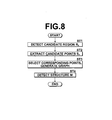
- FIG. 8 is a flow chart illustrating the flow of a process to detect a structure by the structure detection device.
- the candidate region detecting means 10 detects the candidate region R c from the image data DV (step ST1, see FIG. 2 ).
- the candidate point extracting means 20 extracts the (primary) candidate points S p0 from the candidate region R c , and extracts the (secondary) candidate points S p by segmentation (step ST2, see FIG. 3 ).
- the normalizing means 30 performs normalization, and the corresponding point selecting means 40 selects, from the candidate points S p , the set of corresponding points forming the graph structure M s that is most similar to the shape model M ref , according to Equation (5) (step ST3, see FIG. 4 ).
- the structure detecting means 50 detects the structure M based on the optimal paths connecting the selected corresponding points via other candidate points (step ST4).
- the candidate points belong to the predetermined structure M are extracted from the image data DV.
- the corresponding points forming the graph structure M s that matches or is most similar to the shape model M ref which is formed by the model labels T q having a predetermined connection relationship, represents a known shape of the structure M and is stored in advance in the shape model storing means DB, are selected under the following constraints (a) to (c): (a) each model label is mapped with only one of the candidate points or none of the candidate points; (b) each candidate point is mapped with only one of the model labels or none of the model labels; and (c) when a path between two candidate points which are mapped with each pair of the model labels connected with each other is determined, each candidate point which is mapped with none of the model labels is included in only one of the determined paths or none of the determined paths.
- the structure M is detected from the image data DV using the selected corresponding points.
- This allows accurate detection of the structure M from the image data DV.
- the constraint (c) serves to exclude a mapping between the candidate points and the model labels which has overlapped paths connecting the corresponding points, such as the graph structure M s 1 shown in FIG. 11A or the graph structure M s 2 shown in FIG. 12A , thereby improving the accuracy of the detection of the structure M compared to the conventional method disclosed in Patent Document 1, or the like.
- the corresponding point selecting means 40 selects the corresponding points under the constraint where an arbitrary candidate point S p belonging to set P and an arbitrary model label T q belonging to the set Q satisfy Equation (4) above, a mapping between the candidate point and the model label with overlapped paths connecting the corresponding points can be excluded, thereby allowing accurate detection of the structure M from the image data DV.
- the image processing device, method and program of the invention are also applicable to extraction of the trachea, the intestines, the cerebral vessels, the pulmonary vessels, the hepatic vessels or the bronchial tubes, for example.
- a shape model corresponding to the structure M is stored in the shape model storing means DB, and the corresponding points are selected using a designed shape depending on the type of the structure M.
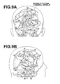
- the model labels T 1 to T 12 are extracted from the arteries, which are the predetermined structure M, and the model label T 13 to T 25 are extracted from the veins.
- the shape model (graph) M ref is formed by connecting predetermined labels among the model labels T1 to T25 by edges (lines).
- the image processing device, method and program of the invention are also applicable to a case where graph structures which are extracted from a plurality of images taken by imaging the same patient at different phases are mapped with each other.
- one of the graph structures extracted from one of phases may be used as the shape model, and nodes forming the graph structure may be used as the model labels.
- the normalizing means 30 and the structure detecting means 50 are optional.
- the structure detection device 1 may further include a display control means for displaying the different sub-structures in different colors.
- the corresponding point selecting means 40 may select the corresponding points by using coordinates of the candidate points and radii or luminance values of the blood vessels at the candidate points.
Landscapes
- Engineering & Computer Science (AREA)
- Computer Vision & Pattern Recognition (AREA)
- Theoretical Computer Science (AREA)
- Physics & Mathematics (AREA)
- General Physics & Mathematics (AREA)
- Software Systems (AREA)
- Computing Systems (AREA)
- Artificial Intelligence (AREA)
- Health & Medical Sciences (AREA)
- Databases & Information Systems (AREA)
- Evolutionary Computation (AREA)
- General Health & Medical Sciences (AREA)
- Medical Informatics (AREA)
- Multimedia (AREA)
- Apparatus For Radiation Diagnosis (AREA)
- Image Analysis (AREA)
- Image Processing (AREA)
Applications Claiming Priority (1)
| Application Number | Priority Date | Filing Date | Title |
|---|---|---|---|
| JP2011209246A JP5395868B2 (ja) | 2011-09-26 | 2011-09-26 | 画像処理装置および方法ならびにプログラム |
Publications (2)
| Publication Number | Publication Date |
|---|---|
| EP2573713A2 true EP2573713A2 (de) | 2013-03-27 |
| EP2573713A3 EP2573713A3 (de) | 2014-10-15 |
Family
ID=47323835
Family Applications (1)
| Application Number | Title | Priority Date | Filing Date |
|---|---|---|---|
| EP12185805.4A Withdrawn EP2573713A3 (de) | 2011-09-26 | 2012-09-25 | Bildverarbeitungsvorrichtung, Verfahren und Programm |
Country Status (3)
| Country | Link |
|---|---|
| US (2) | US8897576B2 (de) |
| EP (1) | EP2573713A3 (de) |
| JP (1) | JP5395868B2 (de) |
Families Citing this family (4)
| Publication number | Priority date | Publication date | Assignee | Title |
|---|---|---|---|---|
| DE102009014763B4 (de) * | 2009-03-25 | 2018-09-20 | Siemens Healthcare Gmbh | Verfahren und Datenverarbeitungssystem zur Bestimmung des Kalziumanteils in Herzkranzgefäßen |
| JP6311404B2 (ja) * | 2014-03-31 | 2018-04-18 | 富士通株式会社 | 管理プログラム、管理装置および管理方法 |
| US9514530B2 (en) | 2014-04-16 | 2016-12-06 | Heartflow, Inc. | Systems and methods for image-based object modeling using multiple image acquisitions or reconstructions |
| US9928602B2 (en) * | 2015-12-11 | 2018-03-27 | Novartis Ag | Fast and automated segmentation of layered image with heuristic graph search |
Citations (3)
| Publication number | Priority date | Publication date | Assignee | Title |
|---|---|---|---|---|
| JP2009048679A (ja) | 2007-08-15 | 2009-03-05 | Sony Corp | 記憶装置の駆動方法 |
| JP2009069895A (ja) | 2007-09-10 | 2009-04-02 | Fuji Xerox Co Ltd | 文書管理システム |
| JP2011098195A (ja) | 2009-10-08 | 2011-05-19 | Fujifilm Corp | 構造物検出装置および方法ならびにプログラム |
Family Cites Families (6)
| Publication number | Priority date | Publication date | Assignee | Title |
|---|---|---|---|---|
| US20050267657A1 (en) * | 2004-05-04 | 2005-12-01 | Devdhar Prashant P | Method for vehicle classification |
| US20070047790A1 (en) * | 2005-08-30 | 2007-03-01 | Agfa-Gevaert N.V. | Method of Segmenting Anatomic Entities in Digital Medical Images |
| US7672482B2 (en) * | 2006-05-16 | 2010-03-02 | Eastman Kodak Company | Shape detection using coherent appearance modeling |
| WO2009031155A2 (en) * | 2007-09-06 | 2009-03-12 | Yeda Research And Development Co. Ltd. | Modelization of objects in images |
| JP4717935B2 (ja) * | 2009-03-23 | 2011-07-06 | 富士フイルム株式会社 | 画像処理装置および方法並びにプログラム |
| JP4981938B2 (ja) * | 2010-03-08 | 2012-07-25 | 富士フイルム株式会社 | 診断支援装置、冠動脈解析プログラムおよび冠動脈解析方法 |
-
2011
- 2011-09-26 JP JP2011209246A patent/JP5395868B2/ja active Active
-
2012
- 2012-09-25 EP EP12185805.4A patent/EP2573713A3/de not_active Withdrawn
- 2012-09-25 US US13/626,503 patent/US8897576B2/en active Active
-
2014
- 2014-11-14 US US14/542,418 patent/US9336458B2/en active Active
Patent Citations (3)
| Publication number | Priority date | Publication date | Assignee | Title |
|---|---|---|---|---|
| JP2009048679A (ja) | 2007-08-15 | 2009-03-05 | Sony Corp | 記憶装置の駆動方法 |
| JP2009069895A (ja) | 2007-09-10 | 2009-04-02 | Fuji Xerox Co Ltd | 文書管理システム |
| JP2011098195A (ja) | 2009-10-08 | 2011-05-19 | Fujifilm Corp | 構造物検出装置および方法ならびにプログラム |
Also Published As
| Publication number | Publication date |
|---|---|
| JP5395868B2 (ja) | 2014-01-22 |
| US20150071553A1 (en) | 2015-03-12 |
| US20130077872A1 (en) | 2013-03-28 |
| JP2013066667A (ja) | 2013-04-18 |
| US8897576B2 (en) | 2014-11-25 |
| EP2573713A3 (de) | 2014-10-15 |
| US9336458B2 (en) | 2016-05-10 |
Similar Documents
| Publication | Publication Date | Title |
|---|---|---|
| EP2309424B1 (de) | Vorrichtung und Verfahren zur Strukturerkennung und computerlesbares Programmspeichermedium dafür | |
| US10079071B1 (en) | Method and system for whole body bone removal and vascular visualization in medical image data | |
| US8693753B2 (en) | Medical image processing device, method and program | |
| Bernard et al. | Standardized evaluation system for left ventricular segmentation algorithms in 3D echocardiography | |
| JP5478171B2 (ja) | 冠動脈画像データの分類のための方法及び装置 | |
| US8538109B2 (en) | Method and system for dynamic pulmonary trunk modeling and intervention planning | |
| Badura et al. | Soft computing approach to 3D lung nodule segmentation in CT | |
| JP5748636B2 (ja) | 画像処理装置および方法並びにプログラム | |
| CN112308846B (zh) | 血管分割方法、装置及电子设备 | |
| EP2810598A1 (de) | Chirurgische hilfsvorrichtung, chirurgisches hilfsverfahren und chirurgisches hilfsprogramm | |
| US12079989B2 (en) | Identifying boundaries of lesions within image data | |
| US20110218427A1 (en) | Diagnosis assisting apparatus, coronary artery analyzing method and recording medium having a coronary artery analyzing program stored therein | |
| US20120275682A1 (en) | Tree structure extraction apparatus, method and program | |
| JP2013192624A (ja) | 医用画像診断支援装置、医用画像診断支援方法ならびにコンピュータプログラム | |
| WO2014045539A1 (ja) | 画像処理装置および方法ならびにプログラム | |
| Tahoces et al. | Deep learning method for aortic root detection | |
| US9336458B2 (en) | Image processing device, method and program | |
| Zhao et al. | Automatic aortic dissection centerline extraction via morphology-guided CRN tracker | |
| US10395773B2 (en) | Automatic characterization of Agatston score from coronary computed tomography | |
| Tziritas | Fully-automatic segmentation of cardiac images using 3-D MRF model optimization and substructures tracking | |
| JP2011161104A (ja) | 画像生成装置、画像生成方法、及びそのプログラム | |
| Jeon et al. | Maximum a posteriori estimation method for aorta localization and coronary seed identification | |
| WO2025128004A1 (en) | Systems and methods for vasculature centreline extraction | |
| US20220067928A1 (en) | Method for locating and characterizing bifurcations of a cerebral vascular tree, associated methods and devices | |
| Rodriguez-Lopez et al. | Automatic ventricle detection in computed tomography pulmonary angiography |
Legal Events
| Date | Code | Title | Description |
|---|---|---|---|
| PUAI | Public reference made under article 153(3) epc to a published international application that has entered the european phase |
Free format text: ORIGINAL CODE: 0009012 |
|
| AK | Designated contracting states |
Kind code of ref document: A2 Designated state(s): AL AT BE BG CH CY CZ DE DK EE ES FI FR GB GR HR HU IE IS IT LI LT LU LV MC MK MT NL NO PL PT RO RS SE SI SK SM TR |
|
| AX | Request for extension of the european patent |
Extension state: BA ME |
|
| PUAL | Search report despatched |
Free format text: ORIGINAL CODE: 0009013 |
|
| AK | Designated contracting states |
Kind code of ref document: A3 Designated state(s): AL AT BE BG CH CY CZ DE DK EE ES FI FR GB GR HR HU IE IS IT LI LT LU LV MC MK MT NL NO PL PT RO RS SE SI SK SM TR |
|
| AX | Request for extension of the european patent |
Extension state: BA ME |
|
| RIC1 | Information provided on ipc code assigned before grant |
Ipc: G06K 9/62 20060101AFI20140911BHEP Ipc: G06T 7/00 20060101ALI20140911BHEP |
|
| 17P | Request for examination filed |
Effective date: 20150415 |
|
| RBV | Designated contracting states (corrected) |
Designated state(s): AL AT BE BG CH CY CZ DE DK EE ES FI FR GB GR HR HU IE IS IT LI LT LU LV MC MK MT NL NO PL PT RO RS SE SI SK SM TR |
|
| 17Q | First examination report despatched |
Effective date: 20150713 |
|
| STAA | Information on the status of an ep patent application or granted ep patent |
Free format text: STATUS: THE APPLICATION IS DEEMED TO BE WITHDRAWN |
|
| 18D | Application deemed to be withdrawn |
Effective date: 20170419 |