EP2573906B1 - Elektrische Maschine mit verminderten Ventilationsverlusten - Google Patents
Elektrische Maschine mit verminderten Ventilationsverlusten Download PDFInfo
- Publication number
- EP2573906B1 EP2573906B1 EP12185571.2A EP12185571A EP2573906B1 EP 2573906 B1 EP2573906 B1 EP 2573906B1 EP 12185571 A EP12185571 A EP 12185571A EP 2573906 B1 EP2573906 B1 EP 2573906B1
- Authority
- EP
- European Patent Office
- Prior art keywords
- baffle
- rotor
- back iron
- electrical machine
- central shaft
- Prior art date
- Legal status (The legal status is an assumption and is not a legal conclusion. Google has not performed a legal analysis and makes no representation as to the accuracy of the status listed.)
- Active
Links
Images


Classifications
-
- H—ELECTRICITY
- H02—GENERATION; CONVERSION OR DISTRIBUTION OF ELECTRIC POWER
- H02K—DYNAMO-ELECTRIC MACHINES
- H02K9/00—Arrangements for cooling or ventilating
- H02K9/19—Arrangements for cooling or ventilating for machines with closed casing and closed-circuit cooling using a liquid cooling medium, e.g. oil
-
- H—ELECTRICITY
- H02—GENERATION; CONVERSION OR DISTRIBUTION OF ELECTRIC POWER
- H02K—DYNAMO-ELECTRIC MACHINES
- H02K1/00—Details of the magnetic circuit
- H02K1/06—Details of the magnetic circuit characterised by the shape, form or construction
- H02K1/22—Rotating parts of the magnetic circuit
- H02K1/32—Rotating parts of the magnetic circuit with channels or ducts for flow of cooling medium
-
- H—ELECTRICITY
- H02—GENERATION; CONVERSION OR DISTRIBUTION OF ELECTRIC POWER
- H02K—DYNAMO-ELECTRIC MACHINES
- H02K16/00—Machines with more than one rotor or stator
-
- H—ELECTRICITY
- H02—GENERATION; CONVERSION OR DISTRIBUTION OF ELECTRIC POWER
- H02K—DYNAMO-ELECTRIC MACHINES
- H02K2205/00—Specific aspects not provided for in the other groups of this subclass relating to casings, enclosures, supports
- H02K2205/12—Machines characterised by means for reducing windage losses or windage noise
Definitions
- the invention relates to electrical machines. More specifically, the invention relates to liquid coolant flow through electrical machines.
- FIG. 5 A typical liquid cooled electric machine, in this case, a generator 100, is shown in FIG. 5 .
- the generator 100 shown is dual-channel, having two rotors 102 and two stators 104. Each rotor- 102 is surrounded by a stator 104 and an air gap 106 exists between each rotor 102 and each stator 104.
- Liquid coolant 108 is flowed through a hollow shaft 110 and is sprayed outwardly from the shaft 110 across rotor windings 112 and stator windings 114 to cool them and other components of the generator 100.
- the coolant 108 then is returned, via gravity, to a sump 116 of the generator 100.
- the coolant exits the generator 100 through one or more scavenge ports 118 for recirculation through the system.
- Such liquid cooled generators 100 typically have poor coolant management leading to insufficient or slow scavenging leading to buildup of coolant levels in the sump 116. If the coolant level reaches the air gap 106, the result is greatly increased windage and friction losses as the rotor 102 rotates through the accumulated coolant 108. Such increased losses can lead to rotor and/or stator failure.
- US 6087744 discloses the use of coolant circulation to cool a stator and a rotor of an electrical machine.
- JP 2011 142785A discloses a cooling device for a motor that is capable of cooling with high efficiency through use of a lubricant.
- an electrical machine comprising: a rotor disposed on a central shaft, wherein the central shaft is hollow; a stator disposed radially outboard of the rotor and secured at a back iron; and a first baffle disposed coupled to the central shaft at one axial end of the rotor; wherein the first baffle is extending radially outwardly from the shaft into a baffle cavity, said baffle cavity located in the back iron such that a portion of the first baffle closest to the baffle cavity is farthest from said one axial end of the rotor and a portion of the first baffle closest to the central shaft is closest to said one axial end of the rotor; and wherein the first baffle directs a flow of liquid coolant radially, originating from the central shaft, through a plurality of coolant spray openings in the shaft, between the first baffle and a rotor winding, between the first baffle and a stator winding and into the baffle cavity via centrifug
- the electrical machine of the first embodiment may comprise two or more rotors secured at the back iron and arranged axially along a central shaft, wherein the central shaft is hollow; two or more stators, each stator disposed radially outboard of a rotor of the two or more rotors; and a plurality of baffles, each baffle disposed at an axial end of a rotor of the two or more rotors, each baffle of the plurality of baffles extending radially outwardly from the central shaft into a plurality of baffle cavities, said plurality of baffle cavities located in the back iron such that the portion of each baffle that is closest to the respective baffle cavity is farthest from the respective axial end of the rotor and the portion of each baffle that is closest to the central shaft is closest to the respective axial end of the rotor; and wherein the plurality of baffles direct the flow of liquid coolant radially, originating from the central shaft, through a plurality of coolant spray openings in
- a method of flowing coolant through an electrical machine comprising: injecting a flow of liquid coolant substantially radially into an electrical machine cavity from a hollow central shaft through a plurality of coolant spray openings in the shaft; urging the flow of liquid coolant radially outwardly along a rotating baffle disposed at one axial end of a rotor of the electrical machine, the said flow directed between the baffle and a rotor winding, and between the baffle and a stator winding via centrifugal force, the said stator being secured at a back iron; and urging the flow of liquid coolant into a baffle cavity, said baffle cavity located in the back iron such that a radial end of the baffle extends into said baffle cavity wherein a portion of the baffle closest to the baffle cavity is farthest from said one axial end of the rotor, and a portion of the baffle closest to the central shaft is closest to said one axial end of the rotor.
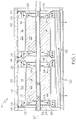
- FIG. 1 Shown in FIG. 1 is an embodiment of an electrical machine 10, for example, a generator.
- the electrical machine 10 described herein is a dual channel electrical machine 10, having two rotors 12 and two stators 14, with each stator 14 surrounding at least a portion of one rotor 12 such that an air gap 16 exists between each rotor 12 and the respective stator 14. It is to be appreciated that while a dual channel electrical machine 10 is shown and described herein, electrical machines 10 with any number of channels, for example, 1, 3 or 4 channels would benefit from utilization of the present disclosure.
- the rotors 12 are located at a central shaft 18 that rotates about a shaft axis 20 and are secured thereto such that the rotors 12 rotate about the shaft axis 20 with the shaft 18.
- Each rotor 12 includes a rotor core 22 with one or more rotor windings 24 having a plurality of rotor conductors located at the rotor core 22.
- the stators 14 are located radially outboard of the respective rotors 12, and are secured to a stator back iron 26, or housing.
- the stators 14 include one or more stator windings 28 having a plurality of stator conductors located at a stator core 30.
- a flow of coolant for example oil 32
- a flow of coolant for example oil 32
- a flow of coolant for example oil 32
- Rotation of the shaft 18 forces the oil 32 radially outwardly toward the rotor winding 24 end turns 40 and stator winding 28 end turns 42.
- thermal energy is transferred to the oil 32 from the rotor end turns 40 and stator end turns 42 (and other components) thus cooling them.
- a baffle 46 is affixed to the shaft 18 and rotates with the shaft 18.
- the baffle 46 extends radially outwardly from the shaft 18 toward the back iron 26, and into a baffle cavity 48 in the back iron 26.
- the baffle 46 contains and directs the oil 32 toward the baffle cavity 48, via centrifugal force due to the rotation of the baffle 46.
- the oil 32 flows to the baffle cavity 48, the oil 32 flows to a scavenge core 50 in the back iron 26 via gravity.
- the oil 32 may then reject the thermal energy gained via, for example, a heat exchanger (not shown) and may be recirculated through the electrical machine 10.
- the baffles 46 located between adjacent rotors 12 additionally prevent cross-flow of coolant from adjacent rotors 12, thus preventing an increased temperature at those near ends 44 of the rotors 12.
- some electrical machines 10 may include one or more back iron cooling channels 52 in the back iron 26 radially outboard of the stator core 30.
- the back iron cooling channels 52 extend axially along and circumferentially around the back iron 26.
- the back iron cooling channels 52 facilitate a flow of coolant therethrough to additional cool the stator 14 at the stator core 30.
- the back iron cooling channels 52 are connected to the baffle cavity 48 such that high pressure oil 32 in the baffle cavity 48, due to the centrifugal force, is urged into the back iron cooling channels 52. As shown, the oil 32 flows into, and circumferentially around the outer back iron cooling channels 52 axially closest to rotor ends 44, then proceeds to inner back iron cooling channels 52.
- the baffle 46 may include enhancements on a baffle face 54 to additionally direct the oil 32 as desired.
- the baffle face 54 may include a plurality of radial grooves 56, or referring to FIG. 4 , the baffle face may include a plurality of curved grooves 58.
- the grooves 56, 58 or other similar enhancements such as ridges or the like, enhance flow of the oil 32 in the radial direction toward the baffle cavity 48.
- the baffle 46 directing the oil 32 to the baffle cavity 48 for scavenging substantially improves scavenge performance, thus reducing a level of oil 32 in a sump thereby reducing windage and friction losses during operation of the electrical machine 10.
Landscapes
- Engineering & Computer Science (AREA)
- Power Engineering (AREA)
- Motor Or Generator Cooling System (AREA)
Claims (11)
- Elektrische Maschine (10), die Folgendes umfasst:einen Rotor (12), der auf einer zentralen Welle (18) angeordnet ist, wobei die zentrale Welle (18) hohl ist:einen Stator (14), der radial außerhalb des Rotors (12) angeordnet ist und an einem Rückschluss (26) befestigt ist; undeine erste Ablenkplatte (46), die an die zentrale Welle gekoppelt (18) an einem axialen Ende (44) des Rotors (12) angeordnet ist;wobei:sich die erste Ablenkplatte (46) radial nach außen von der Welle (18) in einen Ablenkplattenhohlraum (48) erstreckt, wobei sich der Ablenkplattenhohlraum (48) derart in dem Rückschluss (26) befindet, dass ein Abschnitt der ersten Ablenkplatte (46), der dem Ablenkplattenhohlraum (48) am nächsten ist, am weitesten von dem einen axialen Ende (44) des Rotors (12) entfernt ist und dass ein Abschnitt der ersten Ablenkplatte (46), welcher der zentralen Welle (18) am nächsten ist, einem axialen Ende (44) des Rotors am nächsten ist;und wobei die erste Ablenkplatte (46) Strom von flüssigem Kühlmittel (32), ausgehend von der zentralen Welle (18), über Zentrifugalkraft radial durch eine Vielzahl von Kühlmittelsprühöffnungen (36) in die Welle (18), zwischen die erste Ablenkplatte (46) und eine Rotorwicklung (24), zwischen die erste Ablenkplatte (46) und eine Statorwicklung (28) und in die Ablenkplattenhohlraum (48) lenkt.
- Elektrische Maschine (10) nach Anspruch 1, wobei die erste Ablenkplatte (46) eine Vielzahl von Erweiterungen (56, 58) an einer Ablenkplattenfläche (54) beinhaltet, um das flüssige Kühlmittel (32) radial entlang der ersten Ablenkplatte zu lenken.
- Elektrische Maschine (10) nach Anspruch 2, wobei die Ablenkplattenerweiterungen eine Vielzahl von Nuten (56, 58) sind.
- Elektrische Maschine (10) nach Anspruch 1, 2 oder 3, die ferner Folgendes umfasst:eine zweite Ablenkplatte (46), die an einem weiteren axialen Ende des Rotors (12) an die zentrale Welle (18) gekoppelt ist.
- Elektrische Maschine (10) nach einem der vorhergehenden Ansprüche, die ferner eine Vielzahl von Rückschlusskühlkanälen (52) umfasst, die an dem Rückschluss (26) radial außerhalb des Stators (14) angeordnet sind; vorzugsweise
wobei die Vielzahl von Rückschlusskühlkanälen (52) mit dem Ablenkplattenhohlraum (48) verbunden sind, um den Strom des flüssigen Kühlmittels (32) von dem Ablenkplattenhohlraum (48) durch die Vielzahl von Rückschlusskühlkanälen (52) zu ermöglichen. - Elektrische Maschine (10) nach Anspruch 1, die Folgendes umfasst:zwei oder mehr Rotoren (12), die an dem Rückschluss (26) befestigt sind und radial entlang einer zentralen Welle (18) angeordnet sind, wobei die zentrale Welle (18) hohl ist;zwei oder mehr Statoren (14), wobei jeder Stator radial außerhalb eines Rotors der zwei oder mehr Rotoren (12) angeordnet ist; undeine Vielzahl von Ablenkplatten (46), wobei jede Ablenkplatte an einem axialen Ende (44) eines Rotors der zwei oder mehr Rotoren (12) angeordnet ist, wobei sich jede Ablenkplatte der Vielzahl von Ablenkplatten (46) radial nach außen von der zentralen Welle (18) in eine Vielzahl von Ablenkplattenhohlräumen (48) erstreckt, wobei sich die Vielzahl von Ablenkplattenhohlräumen (48) derart in dem Rückschluss (26) befindet, dass der Abschnitt von jeder Ablenkplatte, die dem jeweiligen Ablenkplattenhohlraum am nächsten ist, am weitesten von dem jeweiligen axialen Ende (44) des Rotors entfernt ist und der Abschnitt von jeder Ablenkplatte, die der zentralen Welle (18) am nächsten ist, dem jeweiligen axialen Ende des Rotors am nächsten ist;und wobei die Vielzahl von Ablenkplatten (46) den Strom von flüssigem Kühlmittel (32), ausgehend von der zentralen Welle (16), über Zentrifugalkraft radial durch eine Vielzahl von Kühlmittelsprühöffnungen (36) in der Welle (18), zwischen jede der Vielzahl von Ablenkplatten (46) und eine Rotorwicklung (24), zwischen jede der Vielzahl von Ablenkplatten (46) und einer Statorwicklung (26) und in die Vielzahl von Ablenkplattenhohlräume (48) lenkt.
- Elektrische Maschine (10) nach Anspruch 6, wobei mindestens eine Ablenkplatte der Vielzahl von Ablenkplatten (46) eine Vielzahl von Erweiterungen (56, 58) an einer Ablenkplattenfläche (54) beinhaltet, um das flüssige Kühlmittel (32) radial entlang der Ablenkplatte zu lenken.
- Elektrische Maschine (10) nach Anspruch 7, wobei die Ablenkplattenerweiterungen eine Vielzahl von Nuten (56, 58) sind.
- Elektrische Maschine (10) nach Anspruch 6, 7 und 8, die ferner eine Vielzahl von Rückschlusskühlkanälen (52) umfasst, die an dem Rückschluss (26) radial außerhalb des Stators (14) angeordnet sind; vorzugsweise
wobei die Vielzahl von Rückschlusskühlkanälen (52) mit der Vielzahl von Ablenkplattenhohlräumen (48) verbunden ist, um den Strom von flüssigem Kühlmittel (32) aus der Vielzahl von Ablenkplattenhohlräumen (44) durch die Vielzahl von Rückschlusskühlkanälen (52) zu ermöglichen. - Verfahren zum Strömen von Kühlmittel (32) durch eine elektrische Maschine (10), das Folgendes umfasst:Einspritzen eines Stroms von flüssigem Kühlmittel (32) im Wesentlichen radial in einen Hohlraum einer elektrischen Maschine aus einer hohlen zentralen Welle (18) durch eine Vielzahl von Kühlmittelsprühöffnungen (36) in die Welle (18);Drängen des Stroms von flüssigem Kühlmittel (32) radial nach außen entlang einer sich drehenden Ablenkplatte (46), die an einem axialen Ende (44) eines Rotors (12) der elektrischen Maschine (10) angeordnet ist, wobei der Strom über Zentrifugalkraft zwischen die Ablenkplatte (46) und eine Rotorwicklung (24) und zwischen die Ablenkplatte (46) und eine Statorwicklung (26) eines Stators (14) gelenkt wird, wobei der Stator (14) an einem Rückschluss (26) befestigt ist; undDrängen des Stroms von flüssigem Kühlmittel (32) in einen Ablenkplattenhohlraum (48), wobei sich der Ablenkplattenhohlraum (48) in dem Rückschluss (26) derart befindet, dass sich ein radiales Ende der Ablenkplatte (46) in den Ablenkplattenhohlraum (48) erstreckt, wobei ein Abschnitt der Ablenkplatte (46), welcher der Ablenkplattenhohlraum (48) am nächsten ist, am weitesten von einem axialen Ende (44) des Rotors (12) entfernt ist und ein Abschnitt der Ablenkplatte (46), welcher der axialen Welle (18) am nächsten ist, dem einen axialen Ende (44) des Rotors (12) am nächsten ist.
- Verfahren nach Anspruch 10, das ferner Drängen des Stroms des flüssigen Kühlmittels (32) aus dem Ablenkplattenhohlraum (48) durch einen Rückschlusskühlkanal (52) umfasst, der radial außerhalb eines Stators (14) der elektrischen Maschine (10) angeordnet ist.
Applications Claiming Priority (1)
| Application Number | Priority Date | Filing Date | Title |
|---|---|---|---|
| US13/245,275 US9660505B2 (en) | 2011-09-26 | 2011-09-26 | Electrical machine with reduced windage loss |
Publications (3)
| Publication Number | Publication Date |
|---|---|
| EP2573906A2 EP2573906A2 (de) | 2013-03-27 |
| EP2573906A3 EP2573906A3 (de) | 2016-10-05 |
| EP2573906B1 true EP2573906B1 (de) | 2018-10-31 |
Family
ID=47215368
Family Applications (1)
| Application Number | Title | Priority Date | Filing Date |
|---|---|---|---|
| EP12185571.2A Active EP2573906B1 (de) | 2011-09-26 | 2012-09-22 | Elektrische Maschine mit verminderten Ventilationsverlusten |
Country Status (2)
| Country | Link |
|---|---|
| US (1) | US9660505B2 (de) |
| EP (1) | EP2573906B1 (de) |
Cited By (1)
| Publication number | Priority date | Publication date | Assignee | Title |
|---|---|---|---|---|
| DE102021133860A1 (de) | 2021-12-20 | 2023-06-22 | Bayerische Motoren Werke Aktiengesellschaft | Strömungselement und Elektrische Maschine mit Strömungselement |
Families Citing this family (26)
| Publication number | Priority date | Publication date | Assignee | Title |
|---|---|---|---|---|
| US8803380B2 (en) * | 2011-06-03 | 2014-08-12 | Remy Technologies, Llc | Electric machine module cooling system and method |
| US20170012501A1 (en) * | 2014-03-26 | 2017-01-12 | Hitachi, Ltd. | Electric Motor, Scraping Member, and Rotor |
| JP6181609B2 (ja) * | 2014-06-30 | 2017-08-16 | ファナック株式会社 | エアパージ構造を備えた電動機 |
| US9831746B2 (en) | 2014-10-28 | 2017-11-28 | Ingersoll-Rand Company | Cooling system for electric rotor machine with symmetrical stator passages |
| US9793782B2 (en) * | 2014-12-12 | 2017-10-17 | Hamilton Sundstrand Corporation | Electrical machine with reduced windage |
| US10483812B2 (en) | 2014-12-31 | 2019-11-19 | Ingersoll-Rand Company | Electrical machine and method of manufacture |
| GB2544275B (en) | 2015-11-09 | 2022-02-16 | Time To Act Ltd | Cooling means for direct drive generators |
| FR3052306B1 (fr) * | 2016-06-06 | 2023-03-03 | Valeo Equip Electr Moteur | Machine electrique tournante refroidie par un liquide de refroidissement |
| WO2018129066A2 (en) * | 2017-01-09 | 2018-07-12 | Carrier Corporation | Motor with internal claw pole stator |
| DE102017201117A1 (de) * | 2017-01-24 | 2018-07-26 | Bayerische Motoren Werke Aktiengesellschaft | Verfahren zum Kühlen einer elektrischen Maschine sowie elektrische Maschine |
| CN110214406A (zh) * | 2017-02-02 | 2019-09-06 | 三菱电机株式会社 | 旋转电机 |
| DE102017223490B3 (de) | 2017-12-21 | 2019-06-27 | Audi Ag | Kühlmittelverteiler für eine Maschinenanordnung sowie entsprechende Maschinenanordnung |
| EP3540918A1 (de) * | 2018-03-13 | 2019-09-18 | FLET GmbH | Elektrofahrzeug |
| US10931171B2 (en) * | 2018-09-27 | 2021-02-23 | Ge Aviation Systems Llc | Method and apparatus for cooling a rotor assembly |
| US11146146B2 (en) * | 2018-11-13 | 2021-10-12 | General Electric Company | Apparatus and method for cooling endwindings in a rotating electric machine |
| DE102019131081A1 (de) * | 2019-11-18 | 2021-05-20 | Audi Ag | Elektrische Maschine |
| DE102019131082A1 (de) * | 2019-11-18 | 2021-05-20 | Audi Ag | Elektrische Maschine |
| DE102020200549A1 (de) | 2020-01-17 | 2021-07-22 | Mahle International Gmbh | Rotorwelle eines Elektromotors |
| WO2022115058A1 (en) * | 2020-11-30 | 2022-06-02 | Dereli Izzet | An arrangement for alternators or electric motors |
| FR3125178A1 (fr) * | 2021-07-12 | 2023-01-13 | Nidec Psa Emotors | Machine électrique tournante |
| JP7584372B2 (ja) | 2021-07-26 | 2024-11-15 | 日立Astemo株式会社 | 回転電機 |
| WO2023017077A1 (de) * | 2021-08-10 | 2023-02-16 | Zf Friedrichshafen Ag | Kühlungsanordnung zum kühlen eines hybridfahrzeugs oder eines elektrisch angetriebenen fahrzeugs |
| US20250079917A1 (en) * | 2023-09-01 | 2025-03-06 | Borgwarner Inc. | Rotor having a plurality of cooling jets and electric motor including the same |
| DE102023212607A1 (de) | 2023-12-13 | 2025-06-18 | Robert Bosch Gesellschaft mit beschränkter Haftung | Elektrische Antriebseinheit und ein Verfahren zum Betreiben einer solchen |
| CN119298530A (zh) * | 2024-12-16 | 2025-01-10 | 绍兴文理学院 | 一种具有多个模块化定子的深海机器人驱动电机 |
| CN119315760A (zh) * | 2024-12-18 | 2025-01-14 | 绍兴文理学院 | 一种用于深海机器人驱动电机的散热叶轮结构 |
Citations (4)
| Publication number | Priority date | Publication date | Assignee | Title |
|---|---|---|---|---|
| FR1385664A (fr) * | 1963-12-13 | 1965-01-15 | Worthington Corp | Machine dynamo-électrique à refroidissement par un liquide |
| DE19624519A1 (de) * | 1996-06-20 | 1998-01-02 | Bosch Gmbh Robert | Flüssigkeitskühlung von elektrischen Maschinen |
| EP1065376A2 (de) * | 1999-06-29 | 2001-01-03 | SANYO ELECTRIC Co., Ltd. | Hermetischer Verdichter |
| JP2002186215A (ja) * | 2000-10-06 | 2002-06-28 | Hitachi Ltd | 車両用交流発電機 |
Family Cites Families (15)
| Publication number | Priority date | Publication date | Assignee | Title |
|---|---|---|---|---|
| US2610992A (en) * | 1950-05-16 | 1952-09-16 | Westinghouse Electric Corp | Construction of dynamoelectric machines |
| US3407317A (en) * | 1966-02-21 | 1968-10-22 | Allis Chalmers Mfg Co | Ventilation system for rotating electrical machinery |
| US3518467A (en) * | 1968-11-04 | 1970-06-30 | Emerson Electric Co | Totally enclosed fan-cooled electric motor |
| US3725706A (en) * | 1971-07-26 | 1973-04-03 | Gen Electric | Heat transfer system for dynamoelectric machine |
| US5714819A (en) * | 1996-10-28 | 1998-02-03 | Ametek, Inc. | Motor having universal fan end bracket |
| IT1301920B1 (it) * | 1997-08-26 | 2000-07-07 | Bosch Gmbh Robert | Macchina elettrica. |
| US6727609B2 (en) * | 2001-08-08 | 2004-04-27 | Hamilton Sundstrand Corporation | Cooling of a rotor for a rotary electric machine |
| US7193342B2 (en) | 2002-12-17 | 2007-03-20 | Caterpillar Inc | Apparatus for cooling of electrical devices |
| US7157818B2 (en) * | 2003-11-17 | 2007-01-02 | Emerson Electric Co. | Low noise ventilation system for electric motor |
| US20080303360A1 (en) * | 2007-06-11 | 2008-12-11 | Hewlett-Packard Development Company L.P. | Insulated bearing motor assembly |
| JP4486114B2 (ja) * | 2007-09-03 | 2010-06-23 | 株式会社日立製作所 | 回転電機 |
| JP4363479B2 (ja) * | 2007-11-09 | 2009-11-11 | トヨタ自動車株式会社 | 回転電機および駆動装置 |
| US20100176670A1 (en) * | 2009-01-12 | 2010-07-15 | Power Group International Corporation | Machine cooling scheme |
| JP5446892B2 (ja) * | 2010-01-08 | 2014-03-19 | トヨタ自動車株式会社 | モータの冷却装置 |
| DE102010001705A1 (de) * | 2010-02-09 | 2011-08-11 | Siemens Aktiengesellschaft, 80333 | Elektrische Maschine |
-
2011
- 2011-09-26 US US13/245,275 patent/US9660505B2/en active Active
-
2012
- 2012-09-22 EP EP12185571.2A patent/EP2573906B1/de active Active
Patent Citations (4)
| Publication number | Priority date | Publication date | Assignee | Title |
|---|---|---|---|---|
| FR1385664A (fr) * | 1963-12-13 | 1965-01-15 | Worthington Corp | Machine dynamo-électrique à refroidissement par un liquide |
| DE19624519A1 (de) * | 1996-06-20 | 1998-01-02 | Bosch Gmbh Robert | Flüssigkeitskühlung von elektrischen Maschinen |
| EP1065376A2 (de) * | 1999-06-29 | 2001-01-03 | SANYO ELECTRIC Co., Ltd. | Hermetischer Verdichter |
| JP2002186215A (ja) * | 2000-10-06 | 2002-06-28 | Hitachi Ltd | 車両用交流発電機 |
Cited By (1)
| Publication number | Priority date | Publication date | Assignee | Title |
|---|---|---|---|---|
| DE102021133860A1 (de) | 2021-12-20 | 2023-06-22 | Bayerische Motoren Werke Aktiengesellschaft | Strömungselement und Elektrische Maschine mit Strömungselement |
Also Published As
| Publication number | Publication date |
|---|---|
| US20130076169A1 (en) | 2013-03-28 |
| EP2573906A3 (de) | 2016-10-05 |
| US9660505B2 (en) | 2017-05-23 |
| EP2573906A2 (de) | 2013-03-27 |
Similar Documents
| Publication | Publication Date | Title |
|---|---|---|
| EP2573906B1 (de) | Elektrische Maschine mit verminderten Ventilationsverlusten | |
| US10038355B2 (en) | Electric machine having rotor and stator cooling assembly | |
| CN103155382B (zh) | 电机中的定子组件的内部冷却 | |
| US11018539B2 (en) | Electric machine with helical cooling channels | |
| US8648505B2 (en) | Electrical machine with multiple cooling flows and cooling method | |
| US8026643B2 (en) | Electrical machine with an internally cooled rotor | |
| US8035261B2 (en) | Method and device for cooling an electric machine | |
| CN106849434B (zh) | 转子、液体冷却的电机以及车辆 | |
| JP5374902B2 (ja) | モータの油冷構造 | |
| US11742721B2 (en) | Rotor cooling assembly and method for the interior of a permanent magnet motor | |
| CN111884428A (zh) | 电机、电机冷却系统及电动车 | |
| US20190207449A1 (en) | Rotor for an Electric Machine | |
| EP3713051B1 (de) | Rotoranordnung und kühlverfahren | |
| EP3404802B1 (de) | Generator mit verbesserter statorkühlung und reduziertem ventilationsverlust | |
| US12027922B2 (en) | Rotor assembly and method for motor end winding cooling and bearing lubrication | |
| EP2490320B1 (de) | Kühlung einer elektrischen Permanentmagnetmaschine | |
| EP3716448A1 (de) | Endwindungskühlung | |
| US20160020673A1 (en) | Rotor cooling | |
| WO2020176572A1 (en) | Electric machine with internal cooling passageways | |
| US9257881B2 (en) | Rotating electric machine | |
| US20230026557A1 (en) | An electric machine and method for cooling an electric machine | |
| EP3070816B1 (de) | Verfahren und anordnung zur kühlung einer elektrischen maschine | |
| EP2918003B1 (de) | Verfahren und vorrichtung zur flüssigkeitskühlung eines elektromotors | |
| WO2024132522A1 (en) | Rotor for an electric machine and electric machine | |
| JP2010172129A (ja) | 回転電機の冷却方法及び回転電機の冷却装置 |
Legal Events
| Date | Code | Title | Description |
|---|---|---|---|
| PUAI | Public reference made under article 153(3) epc to a published international application that has entered the european phase |
Free format text: ORIGINAL CODE: 0009012 |
|
| AK | Designated contracting states |
Kind code of ref document: A2 Designated state(s): AL AT BE BG CH CY CZ DE DK EE ES FI FR GB GR HR HU IE IS IT LI LT LU LV MC MK MT NL NO PL PT RO RS SE SI SK SM TR |
|
| AX | Request for extension of the european patent |
Extension state: BA ME |
|
| PUAL | Search report despatched |
Free format text: ORIGINAL CODE: 0009013 |
|
| RIC1 | Information provided on ipc code assigned before grant |
Ipc: H02K 9/19 20060101AFI20160824BHEP Ipc: H02K 5/20 20060101ALN20160824BHEP Ipc: H02K 1/32 20060101ALN20160824BHEP |
|
| AK | Designated contracting states |
Kind code of ref document: A3 Designated state(s): AL AT BE BG CH CY CZ DE DK EE ES FI FR GB GR HR HU IE IS IT LI LT LU LV MC MK MT NL NO PL PT RO RS SE SI SK SM TR |
|
| AX | Request for extension of the european patent |
Extension state: BA ME |
|
| STAA | Information on the status of an ep patent application or granted ep patent |
Free format text: STATUS: REQUEST FOR EXAMINATION WAS MADE |
|
| 17P | Request for examination filed |
Effective date: 20170330 |
|
| RBV | Designated contracting states (corrected) |
Designated state(s): AL AT BE BG CH CY CZ DE DK EE ES FI FR GB GR HR HU IE IS IT LI LT LU LV MC MK MT NL NO PL PT RO RS SE SI SK SM TR |
|
| STAA | Information on the status of an ep patent application or granted ep patent |
Free format text: STATUS: EXAMINATION IS IN PROGRESS |
|
| 17Q | First examination report despatched |
Effective date: 20170523 |
|
| REG | Reference to a national code |
Ref country code: DE Ref legal event code: R079 Ref document number: 602012052814 Country of ref document: DE Free format text: PREVIOUS MAIN CLASS: H02K0001320000 Ipc: H02K0009190000 |
|
| GRAP | Despatch of communication of intention to grant a patent |
Free format text: ORIGINAL CODE: EPIDOSNIGR1 |
|
| STAA | Information on the status of an ep patent application or granted ep patent |
Free format text: STATUS: GRANT OF PATENT IS INTENDED |
|
| RIC1 | Information provided on ipc code assigned before grant |
Ipc: H02K 1/32 20060101ALN20180326BHEP Ipc: H02K 16/00 20060101ALN20180326BHEP Ipc: H02K 5/20 20060101ALN20180326BHEP Ipc: H02K 9/19 20060101AFI20180326BHEP |
|
| RIC1 | Information provided on ipc code assigned before grant |
Ipc: H02K 5/20 20060101ALN20180405BHEP Ipc: H02K 1/32 20060101ALN20180405BHEP Ipc: H02K 9/19 20060101AFI20180405BHEP Ipc: H02K 16/00 20060101ALN20180405BHEP |
|
| INTG | Intention to grant announced |
Effective date: 20180430 |
|
| GRAS | Grant fee paid |
Free format text: ORIGINAL CODE: EPIDOSNIGR3 |
|
| GRAA | (expected) grant |
Free format text: ORIGINAL CODE: 0009210 |
|
| STAA | Information on the status of an ep patent application or granted ep patent |
Free format text: STATUS: THE PATENT HAS BEEN GRANTED |
|
| AK | Designated contracting states |
Kind code of ref document: B1 Designated state(s): AL AT BE BG CH CY CZ DE DK EE ES FI FR GB GR HR HU IE IS IT LI LT LU LV MC MK MT NL NO PL PT RO RS SE SI SK SM TR |
|
| REG | Reference to a national code |
Ref country code: CH Ref legal event code: EP Ref country code: GB Ref legal event code: FG4D |
|
| REG | Reference to a national code |
Ref country code: AT Ref legal event code: REF Ref document number: 1060576 Country of ref document: AT Kind code of ref document: T Effective date: 20181115 |
|
| REG | Reference to a national code |
Ref country code: DE Ref legal event code: R096 Ref document number: 602012052814 Country of ref document: DE |
|
| REG | Reference to a national code |
Ref country code: IE Ref legal event code: FG4D |
|
| REG | Reference to a national code |
Ref country code: NL Ref legal event code: MP Effective date: 20181031 |
|
| REG | Reference to a national code |
Ref country code: LT Ref legal event code: MG4D |
|
| REG | Reference to a national code |
Ref country code: AT Ref legal event code: MK05 Ref document number: 1060576 Country of ref document: AT Kind code of ref document: T Effective date: 20181031 |
|
| PG25 | Lapsed in a contracting state [announced via postgrant information from national office to epo] |
Ref country code: FI Free format text: LAPSE BECAUSE OF FAILURE TO SUBMIT A TRANSLATION OF THE DESCRIPTION OR TO PAY THE FEE WITHIN THE PRESCRIBED TIME-LIMIT Effective date: 20181031 Ref country code: LV Free format text: LAPSE BECAUSE OF FAILURE TO SUBMIT A TRANSLATION OF THE DESCRIPTION OR TO PAY THE FEE WITHIN THE PRESCRIBED TIME-LIMIT Effective date: 20181031 Ref country code: AT Free format text: LAPSE BECAUSE OF FAILURE TO SUBMIT A TRANSLATION OF THE DESCRIPTION OR TO PAY THE FEE WITHIN THE PRESCRIBED TIME-LIMIT Effective date: 20181031 Ref country code: PL Free format text: LAPSE BECAUSE OF FAILURE TO SUBMIT A TRANSLATION OF THE DESCRIPTION OR TO PAY THE FEE WITHIN THE PRESCRIBED TIME-LIMIT Effective date: 20181031 Ref country code: IS Free format text: LAPSE BECAUSE OF FAILURE TO SUBMIT A TRANSLATION OF THE DESCRIPTION OR TO PAY THE FEE WITHIN THE PRESCRIBED TIME-LIMIT Effective date: 20190228 Ref country code: HR Free format text: LAPSE BECAUSE OF FAILURE TO SUBMIT A TRANSLATION OF THE DESCRIPTION OR TO PAY THE FEE WITHIN THE PRESCRIBED TIME-LIMIT Effective date: 20181031 Ref country code: LT Free format text: LAPSE BECAUSE OF FAILURE TO SUBMIT A TRANSLATION OF THE DESCRIPTION OR TO PAY THE FEE WITHIN THE PRESCRIBED TIME-LIMIT Effective date: 20181031 Ref country code: BG Free format text: LAPSE BECAUSE OF FAILURE TO SUBMIT A TRANSLATION OF THE DESCRIPTION OR TO PAY THE FEE WITHIN THE PRESCRIBED TIME-LIMIT Effective date: 20190131 Ref country code: NO Free format text: LAPSE BECAUSE OF FAILURE TO SUBMIT A TRANSLATION OF THE DESCRIPTION OR TO PAY THE FEE WITHIN THE PRESCRIBED TIME-LIMIT Effective date: 20190131 Ref country code: ES Free format text: LAPSE BECAUSE OF FAILURE TO SUBMIT A TRANSLATION OF THE DESCRIPTION OR TO PAY THE FEE WITHIN THE PRESCRIBED TIME-LIMIT Effective date: 20181031 |
|
| PG25 | Lapsed in a contracting state [announced via postgrant information from national office to epo] |
Ref country code: NL Free format text: LAPSE BECAUSE OF FAILURE TO SUBMIT A TRANSLATION OF THE DESCRIPTION OR TO PAY THE FEE WITHIN THE PRESCRIBED TIME-LIMIT Effective date: 20181031 Ref country code: PT Free format text: LAPSE BECAUSE OF FAILURE TO SUBMIT A TRANSLATION OF THE DESCRIPTION OR TO PAY THE FEE WITHIN THE PRESCRIBED TIME-LIMIT Effective date: 20190301 Ref country code: RS Free format text: LAPSE BECAUSE OF FAILURE TO SUBMIT A TRANSLATION OF THE DESCRIPTION OR TO PAY THE FEE WITHIN THE PRESCRIBED TIME-LIMIT Effective date: 20181031 Ref country code: SE Free format text: LAPSE BECAUSE OF FAILURE TO SUBMIT A TRANSLATION OF THE DESCRIPTION OR TO PAY THE FEE WITHIN THE PRESCRIBED TIME-LIMIT Effective date: 20181031 Ref country code: GR Free format text: LAPSE BECAUSE OF FAILURE TO SUBMIT A TRANSLATION OF THE DESCRIPTION OR TO PAY THE FEE WITHIN THE PRESCRIBED TIME-LIMIT Effective date: 20190201 Ref country code: AL Free format text: LAPSE BECAUSE OF FAILURE TO SUBMIT A TRANSLATION OF THE DESCRIPTION OR TO PAY THE FEE WITHIN THE PRESCRIBED TIME-LIMIT Effective date: 20181031 |
|
| PG25 | Lapsed in a contracting state [announced via postgrant information from national office to epo] |
Ref country code: IT Free format text: LAPSE BECAUSE OF FAILURE TO SUBMIT A TRANSLATION OF THE DESCRIPTION OR TO PAY THE FEE WITHIN THE PRESCRIBED TIME-LIMIT Effective date: 20181031 Ref country code: CZ Free format text: LAPSE BECAUSE OF FAILURE TO SUBMIT A TRANSLATION OF THE DESCRIPTION OR TO PAY THE FEE WITHIN THE PRESCRIBED TIME-LIMIT Effective date: 20181031 Ref country code: DK Free format text: LAPSE BECAUSE OF FAILURE TO SUBMIT A TRANSLATION OF THE DESCRIPTION OR TO PAY THE FEE WITHIN THE PRESCRIBED TIME-LIMIT Effective date: 20181031 |
|
| REG | Reference to a national code |
Ref country code: DE Ref legal event code: R097 Ref document number: 602012052814 Country of ref document: DE |
|
| PG25 | Lapsed in a contracting state [announced via postgrant information from national office to epo] |
Ref country code: SM Free format text: LAPSE BECAUSE OF FAILURE TO SUBMIT A TRANSLATION OF THE DESCRIPTION OR TO PAY THE FEE WITHIN THE PRESCRIBED TIME-LIMIT Effective date: 20181031 Ref country code: EE Free format text: LAPSE BECAUSE OF FAILURE TO SUBMIT A TRANSLATION OF THE DESCRIPTION OR TO PAY THE FEE WITHIN THE PRESCRIBED TIME-LIMIT Effective date: 20181031 Ref country code: SK Free format text: LAPSE BECAUSE OF FAILURE TO SUBMIT A TRANSLATION OF THE DESCRIPTION OR TO PAY THE FEE WITHIN THE PRESCRIBED TIME-LIMIT Effective date: 20181031 Ref country code: RO Free format text: LAPSE BECAUSE OF FAILURE TO SUBMIT A TRANSLATION OF THE DESCRIPTION OR TO PAY THE FEE WITHIN THE PRESCRIBED TIME-LIMIT Effective date: 20181031 |
|
| PLBE | No opposition filed within time limit |
Free format text: ORIGINAL CODE: 0009261 |
|
| STAA | Information on the status of an ep patent application or granted ep patent |
Free format text: STATUS: NO OPPOSITION FILED WITHIN TIME LIMIT |
|
| 26N | No opposition filed |
Effective date: 20190801 |
|
| PG25 | Lapsed in a contracting state [announced via postgrant information from national office to epo] |
Ref country code: SI Free format text: LAPSE BECAUSE OF FAILURE TO SUBMIT A TRANSLATION OF THE DESCRIPTION OR TO PAY THE FEE WITHIN THE PRESCRIBED TIME-LIMIT Effective date: 20181031 |
|
| PG25 | Lapsed in a contracting state [announced via postgrant information from national office to epo] |
Ref country code: TR Free format text: LAPSE BECAUSE OF FAILURE TO SUBMIT A TRANSLATION OF THE DESCRIPTION OR TO PAY THE FEE WITHIN THE PRESCRIBED TIME-LIMIT Effective date: 20181031 |
|
| REG | Reference to a national code |
Ref country code: DE Ref legal event code: R119 Ref document number: 602012052814 Country of ref document: DE |
|
| PG25 | Lapsed in a contracting state [announced via postgrant information from national office to epo] |
Ref country code: MC Free format text: LAPSE BECAUSE OF FAILURE TO SUBMIT A TRANSLATION OF THE DESCRIPTION OR TO PAY THE FEE WITHIN THE PRESCRIBED TIME-LIMIT Effective date: 20181031 |
|
| REG | Reference to a national code |
Ref country code: CH Ref legal event code: PL |
|
| PG25 | Lapsed in a contracting state [announced via postgrant information from national office to epo] |
Ref country code: IE Free format text: LAPSE BECAUSE OF NON-PAYMENT OF DUE FEES Effective date: 20190922 Ref country code: DE Free format text: LAPSE BECAUSE OF NON-PAYMENT OF DUE FEES Effective date: 20200401 Ref country code: LU Free format text: LAPSE BECAUSE OF NON-PAYMENT OF DUE FEES Effective date: 20190922 Ref country code: LI Free format text: LAPSE BECAUSE OF NON-PAYMENT OF DUE FEES Effective date: 20190930 Ref country code: CH Free format text: LAPSE BECAUSE OF NON-PAYMENT OF DUE FEES Effective date: 20190930 |
|
| REG | Reference to a national code |
Ref country code: BE Ref legal event code: MM Effective date: 20190930 |
|
| PG25 | Lapsed in a contracting state [announced via postgrant information from national office to epo] |
Ref country code: BE Free format text: LAPSE BECAUSE OF NON-PAYMENT OF DUE FEES Effective date: 20190930 |
|
| PG25 | Lapsed in a contracting state [announced via postgrant information from national office to epo] |
Ref country code: CY Free format text: LAPSE BECAUSE OF FAILURE TO SUBMIT A TRANSLATION OF THE DESCRIPTION OR TO PAY THE FEE WITHIN THE PRESCRIBED TIME-LIMIT Effective date: 20181031 |
|
| PG25 | Lapsed in a contracting state [announced via postgrant information from national office to epo] |
Ref country code: HU Free format text: LAPSE BECAUSE OF FAILURE TO SUBMIT A TRANSLATION OF THE DESCRIPTION OR TO PAY THE FEE WITHIN THE PRESCRIBED TIME-LIMIT; INVALID AB INITIO Effective date: 20120922 Ref country code: MT Free format text: LAPSE BECAUSE OF FAILURE TO SUBMIT A TRANSLATION OF THE DESCRIPTION OR TO PAY THE FEE WITHIN THE PRESCRIBED TIME-LIMIT Effective date: 20181031 |
|
| PG25 | Lapsed in a contracting state [announced via postgrant information from national office to epo] |
Ref country code: MK Free format text: LAPSE BECAUSE OF FAILURE TO SUBMIT A TRANSLATION OF THE DESCRIPTION OR TO PAY THE FEE WITHIN THE PRESCRIBED TIME-LIMIT Effective date: 20181031 |
|
| P01 | Opt-out of the competence of the unified patent court (upc) registered |
Effective date: 20230522 |
|
| PGFP | Annual fee paid to national office [announced via postgrant information from national office to epo] |
Ref country code: GB Payment date: 20250822 Year of fee payment: 14 |
|
| PGFP | Annual fee paid to national office [announced via postgrant information from national office to epo] |
Ref country code: FR Payment date: 20250820 Year of fee payment: 14 |