EP2573931A1 - Elément de production d'énergie et appareil de production d'énergie équipé de l'élément de production d'énergie - Google Patents
Elément de production d'énergie et appareil de production d'énergie équipé de l'élément de production d'énergie Download PDFInfo
- Publication number
- EP2573931A1 EP2573931A1 EP11795381A EP11795381A EP2573931A1 EP 2573931 A1 EP2573931 A1 EP 2573931A1 EP 11795381 A EP11795381 A EP 11795381A EP 11795381 A EP11795381 A EP 11795381A EP 2573931 A1 EP2573931 A1 EP 2573931A1
- Authority
- EP
- European Patent Office
- Prior art keywords
- power generation
- generation element
- magnetostrictive
- magnetostrictive rod
- rod
- Prior art date
- Legal status (The legal status is an assumption and is not a legal conclusion. Google has not performed a legal analysis and makes no representation as to the accuracy of the status listed.)
- Granted
Links
Images


Classifications
-
- H—ELECTRICITY
- H02—GENERATION; CONVERSION OR DISTRIBUTION OF ELECTRIC POWER
- H02N—ELECTRIC MACHINES NOT OTHERWISE PROVIDED FOR
- H02N2/00—Electric machines in general using piezoelectric effect, electrostriction or magnetostriction
- H02N2/18—Electric machines in general using piezoelectric effect, electrostriction or magnetostriction producing electrical output from mechanical input, e.g. generators
- H02N2/185—Electric machines in general using piezoelectric effect, electrostriction or magnetostriction producing electrical output from mechanical input, e.g. generators using fluid streams
-
- H—ELECTRICITY
- H10—SEMICONDUCTOR DEVICES; ELECTRIC SOLID-STATE DEVICES NOT OTHERWISE PROVIDED FOR
- H10N—ELECTRIC SOLID-STATE DEVICES NOT OTHERWISE PROVIDED FOR
- H10N35/00—Magnetostrictive devices
- H10N35/101—Magnetostrictive devices with mechanical input and electrical output, e.g. generators, sensors
-
- H—ELECTRICITY
- H10—SEMICONDUCTOR DEVICES; ELECTRIC SOLID-STATE DEVICES NOT OTHERWISE PROVIDED FOR
- H10N—ELECTRIC SOLID-STATE DEVICES NOT OTHERWISE PROVIDED FOR
- H10N35/00—Magnetostrictive devices
- H10N35/80—Constructional details
-
- H—ELECTRICITY
- H02—GENERATION; CONVERSION OR DISTRIBUTION OF ELECTRIC POWER
- H02N—ELECTRIC MACHINES NOT OTHERWISE PROVIDED FOR
- H02N2/00—Electric machines in general using piezoelectric effect, electrostriction or magnetostriction
-
- H—ELECTRICITY
- H02—GENERATION; CONVERSION OR DISTRIBUTION OF ELECTRIC POWER
- H02N—ELECTRIC MACHINES NOT OTHERWISE PROVIDED FOR
- H02N2/00—Electric machines in general using piezoelectric effect, electrostriction or magnetostriction
- H02N2/18—Electric machines in general using piezoelectric effect, electrostriction or magnetostriction producing electrical output from mechanical input, e.g. generators
- H02N2/186—Vibration harvesters
- H02N2/188—Vibration harvesters adapted for resonant operation
Definitions
- Methods for deforming piezoelectric elements include a method for deforming a piezoelectric element by application of vibration to piezoelectric elements, a method for indirectly applying pressure such as wind pressure or sound pressure, a method for causing an object such as a weight to collide with piezoelectric elements, and a method for attaching piezoelectric elements to a deformed object (for example, refer to Patent Literature 1).
- Patent Literature 1 discloses a sound power generation apparatus which generates power by a piezoelectric element using air pressure fluctuation caused by sound and a vibration power generation apparatus which generates power by piezoelectric elements using pressure fluctuation caused by vibration.
- a method for generating power using a change in magnetic flux of a permanent magnet is a method for generating power by a temporal change in interlinkage magnetic flux density of coil caused by vibration of the permanent magnet, that is, a method for generating power using electromagnetic induction (for example, refer to Non Patent Literature 1 and Patent Literature 2).
- Patent Literature 2 discloses a piezoelectric element including: a bias magnet which is magnetized in two poles; a magnetostrictive material which changes magnetic permeability through a reverse magnetostrictive effect by applying force from outside and changes a flow of magnetic flux; a compressing means which periodically compresses the magnetostrictive material in a direction having magnetic anisotropy; and a coil means which induces current by the periodically changing magnetic flux.
- the magnetostrictive material, the coil, and the compressing means are disposed such that the periodically changing magnetic flux and the coil wound around the coil center form a linkage.
- this is a configuration which generates power with current which is generated in the coil by periodically compressing, in a longitudinal direction, the magnetostrictive material having magnetic anisotropy in a longitudinal direction.
- the piezoelectric element disclosed in Patent Literature 1 has large piezoelectric longitudinal constant and high power generation efficiency of high piezoelectric vertical effect (when the direction of force and the direction of taking out voltage are the same).
- power is generated using bending deformation through deforming a single-plate piezoelectric material, voltage is taken out in a direction perpendicular to a direction of force (piezoelectric horizontal effect), with the result that the power generation efficiency is low.
- the piezoelectric material is a brittle material which is easily damaged by bending and impact. Therefore, there is a problem that an excessive load cannot be applied to the piezoelectric material and it is difficult to apply large bending to and have a large impact on the material for increasing power generation capacity.
- the piezoelectric element has high impedance in low frequency since it is electrically inductive load. There is a demerit that when a load having lower impedance than the piezoelectric element is connected to the piezoelectric element, voltage generated at the load is low, power obtained from power generation is low and power generation efficiency is low.
- Non Patent Literature 1 in the method for generating power using a change in linkage magnetic flux density in the coil caused by the vibration of the permanent magnet as disclosed in Non Patent Literature 1, it is necessary to cause a vibrator to vibrate at large amplitude and high frequency for increasing power generation capacity.
- the size of the permanent magnet used as the vibrator is large, the mass of the vibrator is high while the resonance frequency of the vibrator is low. As a result, there is a problem that the power generation capacity is not increased.
- Patent Literature 2 the method for generating power by periodically compressing the magnetostrictive material disclosed in Patent Literature 2 requires large force for compressing the magnetostrictive material in a longitudinal direction. Moreover, there is a problem that since the compression force is unevenly applied to the magnetostrictive material, power generation efficiency is low.
- the present invention has an object to provide a power generation element which has strong resistance to bending and impact and has high power generation capacity, and an electronic device including the power generation element.
- a power generation element includes: a first magnetostrictive rod made of a magnetostrictive material; a rigid rod made of a magnetic material and disposed in parallel with the first magnetostrictive rod, the magnetic material having rigidity and a shape that enable uniform application of compression force or tensile force to the first magnetostrictive rod; a first coil wound around the first magnetostrictive rod; and two connecting yokes each of which is provided at one end of each of the first magnetostrictive rod and the rigid rod to connect the first magnetostrictive rod and the rigid rod, wherein the power generation element generates power through expansion or contraction of the first magnetostrictive rod due to vibration in a direction perpendicular to an axis direction of the first magnetostrictive rod.
- the rigid rod is a second magnetostrictive rod made of a magnetostrictive material
- the power generation element further includes a second coil wound around the second magnetostrictive rod, and the power generation element generates power through expansion of one of the first magnetostrictive rod and the second magnetostrictive rod and contraction of the other due to vibration in a direction perpendicular to an axis direction of the first magnetostrictive rod and the second magnetostrictive rod.
- the power generation element comprises a combination of the two magnetostrictive rods, one of the two magnetostrictive rods expands and the other contracts when vibration is applied to the power generation element in a direction perpendicular to the axis direction of the two magnetostrictive rods. With this, it is possible to efficiently generate power with small force.
- the magnetostrictive material having resistance to external force such as bending and impact is used for the magnetostrictive rod, it is possible to apply great bending to and have an impact on the power generation element and to increase power generation capacity.
- an easy magnetization direction of the first magnetostrictive rod is in parallel with the axis direction of the first magnetostrictive rod.
- the first coil and the second coil each include K coils connected in parallel and each having N/K turns.
- the power generation apparatus having the power generation element according to an aspect of the present invention includes the power generation element having the above described features.
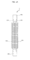
- the magnetostrictive rods 11a and 11b are disposed in parallel.
- One end of each of the magnetostrictive rods 11a and 11b is provided with the connecting yoke 10a for connection of the magnetostrictive rod 11a and the magnetostrictive rod 11a to the connecting yoke 10a.
- the other end of each of the magnetostrictive rods 11a and 11b is provided with the connecting yoke 10b for connection of the magnetostrictive rod 11a and the magnetostrictive rod 11b to the connecting yoke 10b.
- the connecting yokes 10a and 10b are formed with a magnetic material including Fe, for example, and are mechanically and magnetically connected to the magnetostrictive rods 11a and 11b.
- FIGS. 2C to 2J are each a diagram showing the method for joining the magnetostrictive rod 11a and the connecting yoke 10a, and the magnetostrictive rod 11b and the connecting yoke 10a.
- the magnetostrictive rods 11a and 11b and the connecting yoke 10a must be strongly joined with each other because they are used for vibration by the power generation element.
- the following method allows a joint between the magnetostrictive rod 11a and the connecting yoke 10a and a joint between the magnetostrictive rod 11b and the connecting yoke 10a to be solid enough to withstand vibration necessary for power generation.
- the joint between the magnetostrictive rods 11a and 11b and the connecting yoke 10a can be performed by a pinning method for forming a joint between the magnetostrictive rod 11a and the connecting yoke 10a and between the magnetostrictive rod 11b and the connecting yoke 10a through the penetration of a pin.
- the shape of the connecting yoke may be not only the shape shown in FIG. 2C but also the shape shown in FIG. 2I as an example.
- the connecting yoke 10a shown in FIG. 2C has its boundary, with and the magnetostrictive rods 11a and 11b, which is almost perpendicular to the magnetostrictive rods 11a and 11b.
- the connecting yoke 10d shown in FIG. 2I has its boundary, with the magnetostrictive rods 11a and 11b, which slopes toward the magnetostrictive rods 11a and 11b. With this configuration, it is possible to reduce the concentration of stress at the base portion of the magnetostrictive rods 11a and 11b when the magnetostrictive rods 11a and 11b are bent by vibration.
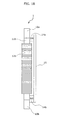
- the back yoke 15, as shown in FIG. 2B includes the permanent magnet 14a provided on the side of the connecting yoke 10a and the permanent magnet 14b provided on the side of the connecting yoke 10b.
- the back yoke 15 is connected to the connecting yoke 10a and the connecting yoke 10b via the permanent magnet 14a and the permanent magnet 14b.
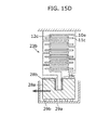
- the power generation element 1, as shown in FIG. 2K may be a configuration in which the back yoke 15 shown in FIG. 1B is replaced with a magnetostrictive rod around which coil is wound.
- FIG. 2K is a side view showing a configuration of a power generation element in which the back yoke is replaced with magnetostrictive rods around which coils are wound.
- the coil 12d is wound around the magnetostrictive rod 11d which replaces the back yoke.
- a movable yoke 10d and a movable yoke 10e are provided at both ends of the magnetostrictive rod 11d.
- the length of the movable yoke 10d is almost the same as the length of the connecting yoke 10a.
- the length of the movable yoke 10b is almost the same as the length of the connecting yoke 10e.
- the movable yoke 10d is connected to the connecting yoke 10a via the permanent magnet 14a.
- the movable yoke 10e is connected to the connecting yoke 10b via the permanent magnet 14b.
- the permanent magnet 14a has a north pole on the surface side connected to the movable yoke 10d and a south pole on the surface side connected to the connecting yoke 10a.
- the permanent magnet 14b has a south pole on the surface side connected to the movable yoke 10e and a north pole on the surface side connected to the connecting yoke 10b.
- the connecting yokes 10a and 10b, the magnetostrictive rods 11a and 11b, the permanent magnets 14a and 14b, and the movable yokes 10d and 10e form a magnetic loop as shown by the lower drawing in FIG. 2K .
- the magnetostrictive rods 11a and 11b are deformed by bending. More specifically, when the power generation element 1 receives the bending force P in a direction shown in FIG. 4A , the magnetostrictive rod 11a expands and the magnetostrictive rod 11b contracts. Moreover, when the connecting yoke 10b receives the bending force P in an opposite direction of the above described bending force P, the magnetostrictive rod 11a contracts and the magnetostrictive rod 11b expands. By the expansion and contraction of the magnetostrictive rods 11a and 11b, the magnetization of the magnetostrictive rods 11a and 11b increases or decrease due to the inverse magnetostrictive effect.
- the magnetic flux density through the coils 12a and 12b is changed. Due to the temporal change in the magnetic flux density, as shown in FIG. 4B , induced voltage (or induced current) is produced in the coils 12a and 12b. Moreover, by the bending vibration of the connecting yoke 10b of the power generation element 1, the vibration can be maintained by resonance and power can be continuously generated.
- the power generation element with a bimorph structure In the power generation element with a bimorph structure, generally, two magnetostrictive plates made of the magnetostrictive material are glued together and then coil is wound around the glued two magnetostrictive plates in one direction.
- the changes in magnetization for the two magnetostrictive plates are opposite in orientation to each other. Therefore, the changes in magnetic flux are offset with each other, with a result that little current is produced in the coil wound around the two magnetostrictive plates.
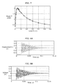
- FIG. 5 is a diagram showing, in voltage, power generation capacity of the power generation element 1 according to the present embodiment.
- the generated voltage can be calculated by the following Expression 1.
- the average generated power P is calculated by the following Expression 3.
- the above described power density value shows that the power generation element 1 using a magnetostrictive material according to the present embodiment can obtain power generation capacity 10 times or larger than power generation using piezoelectric element (1 mW/cm 3 ) or power generation using electret. In other words, the power generation element 1 can realize miniaturization of the element.
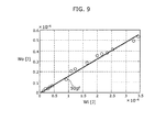
- the relationship between the input workload (input mechanical energy) W i and the output electrical energy W o is almost linear.
- the energy conversion efficiency ⁇ is calculated to be 15%.
- the Joule loss is generated almost equal to the resistance of the coil, the energy conversion efficiency is believed to be greater than or equal to 30%.
- the power generation element 1 in the second resonant mode can generate electric power that is greater than the power generation element in the first resonant mode because the resonance frequency in the second resonant mode is higher than that in the first resonant mode.
- a magnetostrictive material other than Galfenol for example, permendur that is an iron-cobalt alloy and others are acceptable. Moreover, not only a material which is in a crystal condition but also a material which is in an amorphous condition are acceptable. Furthermore, in order to magnify the change in magnetization with respect to tensile stress, a magnetostrictive material to which compression stress is added by stress anneal process in advance can be used.
- the direction of the bending force P applied to the connecting yoke 10b may be various as long as the direction is perpendicular to the axis direction of the magnetostrictive rods 11a and 11b, and one of the magnetostrictive rods 11a and 11b expands and the other contracts.
- the power generation element comprises two magnetostrictive rods.
- the difference from Embodiment 1 is that the power generation element is composed of one magnetostrictive rod and one connecting yoke.
- FIG. 11A is a side view of the power generation element according to the present embodiment.
- FIG. 11B is a side view showing the arrangement positions of a magnetostrictive rod and a connecting yoke of the power generation element shown in FIG. 11A .
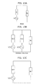
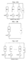
- the load resistance for each of the divided coils 12a (or 12b) is R/K as shown in the equivalent electrical circuit diagram of FIG. 13F when the coil 12a (or 12b) is divided into K coils as shown in FIG. 12D .
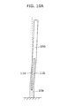
- FIG. 14 is a schematic configuration view of the power generation apparatus in which power generation elements according to Embodiment 1 are connected in series.
- a power generation apparatus 23a includes a fixing unit 24, five power generation elements connected in series to the fixing unit 24, a fixing unit 26, and a weight (mover) 27.
- Each of the power generation elements connected in series includes the magnetostrictive rods 11a and 11b, the coils 12a which is wound around the magnetostrictive rod 11a and the coil 12b which is wound around the magnetostrictive rod 11b, and the connecting yokes 25a, 25b, 25c, and 25d which are connected to the magnetostrictive rods 11a and 11b.
- the five power generation elements are each disposed in parallel, the power generation elements adjacent to each other share the connecting yokes, and the five power generation elements are connected in series.
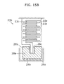
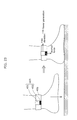
- the power generation apparatus 23b includes a power generation element connecting body in which power generation elements are connected in series, a weight 28a, magnets 28b and 28c each of which is provided a sidewall of the concave portion formed in the weight 28a, a container 29a which houses the weight 28a, and spheres 29b which are provided between the weight 28a and the container 29a.
- the spheres 29b are provided for reducing friction between the weight 28a and the container 29a.
Landscapes
- General Electrical Machinery Utilizing Piezoelectricity, Electrostriction Or Magnetostriction (AREA)
Applications Claiming Priority (2)
| Application Number | Priority Date | Filing Date | Title |
|---|---|---|---|
| JP2010139930 | 2010-06-18 | ||
| PCT/JP2011/003276 WO2011158473A1 (fr) | 2010-06-18 | 2011-06-09 | Elément de production d'énergie et appareil de production d'énergie équipé de l'élément de production d'énergie |
Publications (3)
| Publication Number | Publication Date |
|---|---|
| EP2573931A1 true EP2573931A1 (fr) | 2013-03-27 |
| EP2573931A4 EP2573931A4 (fr) | 2014-03-26 |
| EP2573931B1 EP2573931B1 (fr) | 2015-09-23 |
Family
ID=45347889
Family Applications (1)
| Application Number | Title | Priority Date | Filing Date |
|---|---|---|---|
| EP11795381.0A Active EP2573931B1 (fr) | 2010-06-18 | 2011-06-09 | Elément de production d'énergie et appareil de production d'énergie équipé de l'élément de production d'énergie |
Country Status (7)
| Country | Link |
|---|---|
| US (1) | US8766495B2 (fr) |
| EP (1) | EP2573931B1 (fr) |
| JP (1) | JP4905820B2 (fr) |
| KR (1) | KR101457782B1 (fr) |
| CN (1) | CN102986129B (fr) |
| BR (1) | BR112012032264B8 (fr) |
| WO (1) | WO2011158473A1 (fr) |
Cited By (2)
| Publication number | Priority date | Publication date | Assignee | Title |
|---|---|---|---|---|
| EP2656406A4 (fr) * | 2010-12-21 | 2014-09-17 | Oscilla Power Inc | Appareil de récupération d'énergie de vibration |
| US10944340B2 (en) | 2016-04-19 | 2021-03-09 | National University Corporation Kanazawa University | Power generation element, method for manufacturing power generation element, and actuator |
Families Citing this family (88)
| Publication number | Priority date | Publication date | Assignee | Title |
|---|---|---|---|---|
| US8212436B2 (en) * | 2010-02-01 | 2012-07-03 | Oscilla Power, Inc. | Apparatus for harvesting electrical power from mechanical energy |
| WO2012096289A1 (fr) * | 2011-01-12 | 2012-07-19 | 株式会社ニコン | Générateur d'électricité, dispositif électronique et dispositif de génération d'électricité |
| CN103534925B (zh) * | 2011-05-16 | 2016-01-20 | 国立大学法人金泽大学 | 发电开关 |
| WO2013105280A1 (fr) | 2012-01-12 | 2013-07-18 | 富士通株式会社 | Appareil de production d'énergie |
| JP5954729B2 (ja) * | 2012-01-30 | 2016-07-20 | 株式会社ミツバ | 発電装置 |
| JP2013177664A (ja) * | 2012-02-28 | 2013-09-09 | Yasubumi Furuya | 磁歪振動発電用合金 |
| CN104115392A (zh) * | 2012-03-14 | 2014-10-22 | 富士通株式会社 | 发电装置 |
| JP5940343B2 (ja) * | 2012-03-29 | 2016-06-29 | 東洋ゴム工業株式会社 | 発電素子 |
| JP5940344B2 (ja) * | 2012-03-29 | 2016-06-29 | 東洋ゴム工業株式会社 | 発電ユニット |
| JP5969244B2 (ja) * | 2012-03-29 | 2016-08-17 | 東洋ゴム工業株式会社 | 発電素子 |
| JP5986773B2 (ja) * | 2012-03-29 | 2016-09-06 | 東洋ゴム工業株式会社 | 発電素子 |
| JP5890721B2 (ja) * | 2012-03-29 | 2016-03-22 | 東洋ゴム工業株式会社 | 発電素子 |
| JP5894832B2 (ja) * | 2012-03-29 | 2016-03-30 | 東洋ゴム工業株式会社 | 発電素子 |
| JP5880702B2 (ja) * | 2012-06-13 | 2016-03-09 | 富士通株式会社 | 発電デバイス |
| JP6017199B2 (ja) * | 2012-06-28 | 2016-10-26 | 一登 背戸 | 振動発電装置 |
| JP2014011843A (ja) * | 2012-06-28 | 2014-01-20 | Toyo Tire & Rubber Co Ltd | 振動発電装置及び振動発電装置の設計方法 |
| JP5958121B2 (ja) * | 2012-06-28 | 2016-07-27 | 一登 背戸 | 振動発電装置 |
| WO2014008485A2 (fr) * | 2012-07-05 | 2014-01-09 | Oscilla Power Inc. | Charge axiale pour la génération d'énergie magnétostrictive |
| JP5943423B2 (ja) * | 2012-07-10 | 2016-07-05 | 国立大学法人金沢大学 | 発電装置 |
| JP6074939B2 (ja) * | 2012-07-27 | 2017-02-08 | ソニー株式会社 | 発電機 |
| JP2014033507A (ja) * | 2012-08-01 | 2014-02-20 | Mitsumi Electric Co Ltd | 発電装置 |
| JP2014033508A (ja) * | 2012-08-01 | 2014-02-20 | Mitsumi Electric Co Ltd | 発電素子 |
| JP5916572B2 (ja) * | 2012-09-19 | 2016-05-11 | 住友理工株式会社 | 発電手段付き防振装置 |
| JP5936514B2 (ja) * | 2012-10-17 | 2016-06-22 | 東洋ゴム工業株式会社 | 発電ユニット |
| JP6155009B2 (ja) * | 2012-10-31 | 2017-06-28 | 住友理工株式会社 | 発電装置 |
| JPWO2014069483A1 (ja) * | 2012-11-05 | 2016-09-08 | 旭硝子株式会社 | 振動型発電装置、電源モジュール |
| JP2014096924A (ja) * | 2012-11-09 | 2014-05-22 | Toyo Tire & Rubber Co Ltd | 発電素子 |
| JP6005504B2 (ja) * | 2012-12-25 | 2016-10-12 | 東洋ゴム工業株式会社 | 発電ユニット |
| JP6209818B2 (ja) * | 2012-12-26 | 2017-10-11 | 富士電機株式会社 | 発電装置 |
| JP6093573B2 (ja) * | 2013-01-07 | 2017-03-08 | 東洋ゴム工業株式会社 | 発電素子のカバー |
| JP6028594B2 (ja) * | 2013-01-28 | 2016-11-16 | 富士電機株式会社 | 発電装置 |
| JP6174053B2 (ja) * | 2013-01-30 | 2017-08-09 | 住友理工株式会社 | 磁歪式振動発電装置 |
| JP6068187B2 (ja) * | 2013-02-25 | 2017-01-25 | 東洋ゴム工業株式会社 | 発電素子 |
| EP2988409A4 (fr) * | 2013-04-12 | 2017-03-08 | Mitsumi Electric Co., Ltd. | Dispositif de génération d'électricité |
| US20160072410A1 (en) | 2013-04-12 | 2016-03-10 | Mitsumi Electric Co., Ltd. | Power generator |
| JP6056634B2 (ja) * | 2013-04-25 | 2017-01-11 | 富士通株式会社 | 発電装置 |
| KR101533158B1 (ko) * | 2013-06-13 | 2015-07-02 | 한양대학교 산학협력단 | 열차 내부의 관성력을 이용한 압전 발전 장치 |
| JP6125344B2 (ja) * | 2013-06-20 | 2017-05-10 | 住友理工株式会社 | 磁歪式振動発電装置 |
| JP2015015850A (ja) * | 2013-07-05 | 2015-01-22 | ミツミ電機株式会社 | 発電装置 |
| JP6167731B2 (ja) * | 2013-07-29 | 2017-07-26 | 富士通株式会社 | 振動発電デバイス |
| JP6125366B2 (ja) * | 2013-07-30 | 2017-05-10 | 住友理工株式会社 | 磁歪素子利用の振動発電装置 |
| JP2015037372A (ja) * | 2013-08-14 | 2015-02-23 | ミツミ電機株式会社 | 発電装置 |
| JP6146473B2 (ja) * | 2013-08-16 | 2017-06-14 | 富士通株式会社 | 発電デバイス及びセンサシステム |
| JP6136758B2 (ja) * | 2013-08-23 | 2017-05-31 | 富士通株式会社 | 発電デバイス |
| JP6238343B2 (ja) * | 2013-08-28 | 2017-11-29 | 国立大学法人金沢大学 | 振動電気変換デバイス |
| JP6099538B2 (ja) * | 2013-09-30 | 2017-03-22 | 住友理工株式会社 | 磁歪素子利用の振動発電装置 |
| JP6248538B2 (ja) * | 2013-10-25 | 2017-12-20 | 富士通株式会社 | 巻き線機及び振動発電デバイスの製造方法 |
| JP6064865B2 (ja) * | 2013-10-31 | 2017-01-25 | 富士電機株式会社 | 振動発電装置 |
| JP6183160B2 (ja) * | 2013-10-31 | 2017-08-23 | 富士電機株式会社 | 振動発電装置 |
| JP6153451B2 (ja) * | 2013-11-07 | 2017-06-28 | 東洋ゴム工業株式会社 | 発電素子 |
| KR101582295B1 (ko) * | 2013-11-22 | 2016-01-06 | 한국기계연구원 | 자기형상기억합금을 이용한 에너지 하베스터 |
| WO2015098221A1 (fr) | 2013-12-25 | 2015-07-02 | 住友理工株式会社 | Système de génération d'électricité |
| CN103762891B (zh) * | 2014-01-14 | 2016-01-20 | 杭州电子科技大学 | 柱状超磁致伸缩式俘能器 |
| CN103762890B (zh) * | 2014-01-14 | 2016-01-13 | 杭州电子科技大学 | 采用柔性铰链放大的超磁致伸缩振动能量收集器 |
| JP6171992B2 (ja) * | 2014-03-12 | 2017-08-02 | 富士電機株式会社 | 発電装置 |
| JP6171991B2 (ja) * | 2014-03-12 | 2017-08-02 | 富士電機株式会社 | 発電装置 |
| JP6239411B2 (ja) * | 2014-03-14 | 2017-11-29 | 東洋ゴム工業株式会社 | 発電装置 |
| US10230314B2 (en) | 2014-03-17 | 2019-03-12 | National University Corporation Kanazawa University | Power generation element and actuator using structure of said power generation element |
| FR3019399B1 (fr) * | 2014-03-25 | 2016-03-11 | Valeo Equip Electr Moteur | Roue polaire forgee pour alternateur de vehicule automobile muni d'aimants permanents interpolaires |
| JP6239431B2 (ja) * | 2014-04-09 | 2017-11-29 | 東洋ゴム工業株式会社 | 発電素子 |
| JP6349909B2 (ja) | 2014-04-23 | 2018-07-04 | ミツミ電機株式会社 | 発電装置 |
| JP2015223061A (ja) * | 2014-05-23 | 2015-12-10 | ミツミ電機株式会社 | ベースおよび発電装置 |
| JP6287580B2 (ja) | 2014-05-26 | 2018-03-07 | ミツミ電機株式会社 | 発電装置 |
| JP2016077037A (ja) * | 2014-10-03 | 2016-05-12 | 東洋ゴム工業株式会社 | 発電装置および発電装置の設計方法 |
| JP6156405B2 (ja) * | 2015-02-13 | 2017-07-05 | ミツミ電機株式会社 | 発電装置、発電装置セットおよび発電システム |
| US10447135B2 (en) * | 2015-09-28 | 2019-10-15 | The Curators Of The University Of Missouri | Device for generating electrical power from low frequency oscillations |
| CN105533980B (zh) * | 2016-02-04 | 2017-11-14 | 南京邮电大学 | 发电背带连结扣 |
| JP2017158347A (ja) * | 2016-03-03 | 2017-09-07 | 孝彰 五十嵐 | 充電装置 |
| US20180164165A1 (en) * | 2016-12-08 | 2018-06-14 | Magcanica, Inc. | Devices and methods to stimulate motion in magnetoelastic beams |
| CN111066110B (zh) * | 2018-03-05 | 2022-08-09 | 欧姆龙株式会社 | 开关、显示保持方法以及计算机可读介质 |
| CN109185020A (zh) * | 2018-08-14 | 2019-01-11 | 沈阳工业大学 | 具有能量输出的磁致伸缩薄片式波浪发电装置 |
| JP7218522B2 (ja) * | 2018-09-13 | 2023-02-07 | 富士電機株式会社 | 発電装置 |
| US11980103B2 (en) | 2018-10-19 | 2024-05-07 | National University Corporation Kanazawa University | Power generation element and actuator |
| JP7309457B2 (ja) | 2019-05-31 | 2023-07-18 | キヤノン株式会社 | 発電素子、および発電素子を用いた装置 |
| JP7483328B2 (ja) | 2019-05-31 | 2024-05-15 | キヤノン株式会社 | 発電素子、および発電素子を用いた装置 |
| WO2020246619A1 (fr) * | 2019-06-03 | 2020-12-10 | 西風技研株式会社 | Système de génération de puissance et générateur alimenté par vibration |
| JP6914306B2 (ja) * | 2019-10-08 | 2021-08-04 | 西浦 信一 | 逆磁歪式発電素子、発電装置、発電システム |
| EP4064372A4 (fr) | 2019-11-18 | 2023-12-20 | Sumitomo Metal Mining Co., Ltd. | Élément magnétostrictif et procédé de production d'élément magnétostrictif |
| JP6962666B1 (ja) * | 2020-11-06 | 2021-11-05 | 信一 西浦 | 発電素子及び発電アクチュエータ |
| CN116888312A (zh) | 2021-02-09 | 2023-10-13 | 住友金属矿山株式会社 | 磁致伸缩构件以及磁致伸缩构件的制造方法 |
| US12464952B2 (en) | 2021-02-09 | 2025-11-04 | Sumitomo Metal Mining Co., Ltd. | Magnetostrictive member and method for manufacturing magnetostrictive member |
| IT202100002921A1 (it) | 2021-02-11 | 2022-08-11 | Ottavia S R L S | Modulo tastiera e generatore elettrico applicato ad un modulo tastiera |
| JP7782142B2 (ja) | 2021-04-23 | 2025-12-09 | 住友金属鉱山株式会社 | 磁歪部材及び磁歪部材の製造方法 |
| JP6956293B1 (ja) * | 2021-04-27 | 2021-11-02 | 前田道路株式会社 | 発電システム、及び、アスファルトプラント |
| JP2023018466A (ja) | 2021-07-27 | 2023-02-08 | ヤマハ発動機株式会社 | 振動発電装置及び移動体 |
| JP2024020759A (ja) * | 2022-08-02 | 2024-02-15 | キヤノン株式会社 | 発電素子および発電素子を用いた発電装置 |
| WO2024190194A1 (fr) | 2023-03-10 | 2024-09-19 | 住友金属鉱山株式会社 | Élément magnétostrictif et procédé de production d'élément magnétostrictif |
| JPWO2024190195A1 (fr) | 2023-03-10 | 2024-09-19 |
Family Cites Families (15)
| Publication number | Priority date | Publication date | Assignee | Title |
|---|---|---|---|---|
| US3753058A (en) * | 1970-06-22 | 1973-08-14 | Int Nickel Co | Operation of magnetostrictive apparatus |
| US4845450A (en) * | 1986-06-02 | 1989-07-04 | Raytheon Company | Self-biased modular magnetostrictive driver and transducer |
| JP3315235B2 (ja) * | 1994-01-28 | 2002-08-19 | 株式会社東芝 | 磁歪式アクチュエータ |
| JPH07245970A (ja) * | 1994-03-02 | 1995-09-19 | Calsonic Corp | 圧電素子発電装置 |
| JP3249312B2 (ja) * | 1994-10-28 | 2002-01-21 | 三菱電機株式会社 | 管体伝送装置 |
| JP3541996B2 (ja) * | 1995-09-26 | 2004-07-14 | Tdk株式会社 | 磁歪装置 |
| JPH0990065A (ja) * | 1995-09-28 | 1997-04-04 | Seiko Epson Corp | 発電装置付携帯機器 |
| JP4949666B2 (ja) | 2004-11-11 | 2012-06-13 | 浩平 速水 | 圧電素子、音力発電装置および振動力発電装置 |
| JP4259458B2 (ja) | 2004-11-30 | 2009-04-30 | パナソニック電工株式会社 | 圧電型発電機構 |
| US7471030B2 (en) * | 2006-03-08 | 2008-12-30 | Dynamic Structures And Materials, Llc | Spring biasing locking mechanism for step and repeat motors |
| JP2008072862A (ja) | 2006-09-15 | 2008-03-27 | Citizen Holdings Co Ltd | 発電デバイスおよびそれを備えた発電装置 |
| JP5055505B2 (ja) * | 2007-11-21 | 2012-10-24 | 並木精密宝石株式会社 | 磁歪式多軸駆動アクチュエータ |
| JP2009296734A (ja) * | 2008-06-03 | 2009-12-17 | Shonan-Metaltec Corp | 振動発電機 |
| US7816797B2 (en) * | 2009-01-07 | 2010-10-19 | Oscilla Power Inc. | Method and device for harvesting energy from ocean waves |
| US7816799B2 (en) * | 2009-07-22 | 2010-10-19 | Oscilla Power Inc. | Method and device for energy generation |
-
2011
- 2011-06-09 WO PCT/JP2011/003276 patent/WO2011158473A1/fr not_active Ceased
- 2011-06-09 EP EP11795381.0A patent/EP2573931B1/fr active Active
- 2011-06-09 JP JP2011546472A patent/JP4905820B2/ja active Active
- 2011-06-09 CN CN201180030076.3A patent/CN102986129B/zh active Active
- 2011-06-09 BR BR112012032264A patent/BR112012032264B8/pt not_active IP Right Cessation
- 2011-06-09 KR KR1020127032626A patent/KR101457782B1/ko active Active
-
2012
- 2012-12-17 US US13/716,553 patent/US8766495B2/en active Active
Cited By (2)
| Publication number | Priority date | Publication date | Assignee | Title |
|---|---|---|---|---|
| EP2656406A4 (fr) * | 2010-12-21 | 2014-09-17 | Oscilla Power Inc | Appareil de récupération d'énergie de vibration |
| US10944340B2 (en) | 2016-04-19 | 2021-03-09 | National University Corporation Kanazawa University | Power generation element, method for manufacturing power generation element, and actuator |
Also Published As
| Publication number | Publication date |
|---|---|
| WO2011158473A1 (fr) | 2011-12-22 |
| BR112012032264B8 (pt) | 2022-04-12 |
| EP2573931B1 (fr) | 2015-09-23 |
| EP2573931A4 (fr) | 2014-03-26 |
| JPWO2011158473A1 (ja) | 2013-08-19 |
| BR112012032264B1 (pt) | 2019-11-05 |
| CN102986129A (zh) | 2013-03-20 |
| CN102986129B (zh) | 2016-01-20 |
| KR20130028940A (ko) | 2013-03-20 |
| KR101457782B1 (ko) | 2014-11-03 |
| US20130140919A1 (en) | 2013-06-06 |
| BR112012032264A2 (pt) | 2016-11-29 |
| JP4905820B2 (ja) | 2012-03-28 |
| US8766495B2 (en) | 2014-07-01 |
Similar Documents
| Publication | Publication Date | Title |
|---|---|---|
| EP2573931B1 (fr) | Elément de production d'énergie et appareil de production d'énergie équipé de l'élément de production d'énergie | |
| Tan et al. | Review of MEMS electromagnetic vibration energy harvester | |
| US9571011B2 (en) | Power generating element and power generation device | |
| US9461237B2 (en) | Power generation switch | |
| US7535148B2 (en) | Electromagnetic device for converting mechanical vibrational energy into electrical energy, and manufacture thereof | |
| Wang et al. | A low-frequency, broadband and tri-hybrid energy harvester with septuple-stable nonlinearity-enhanced mechanical frequency up-conversion mechanism for powering portable electronics | |
| US20140333156A1 (en) | Electric power generation device | |
| KR101301695B1 (ko) | 에너지 수확장치 | |
| JPH0990065A (ja) | 発電装置付携帯機器 | |
| KR20150088104A (ko) | 2축 진동 에너지 수확장치 | |
| CN102118095A (zh) | 一种能量采集装置、以及用于能量采集的振动装置和制造方法 | |
| Borowiec et al. | Energy harvesting optimizing with a magnetostrictive cantilever beam system | |
| JP2021141723A (ja) | 発電装置 | |
| KR102150189B1 (ko) | 자석을 이용하는 에너지 하베스팅 장치 | |
| KR101053487B1 (ko) | 진동주파수 변환장치, 진동주파수 변환장치를 이용한 에너지 포집기 및 에너지 포집방법 | |
| KR101582295B1 (ko) | 자기형상기억합금을 이용한 에너지 하베스터 | |
| JP2020078175A (ja) | 発電装置 | |
| KR101025562B1 (ko) | 소리 또는 진동에너지를 이용한 발전모듈과 발전방법 | |
| JP2021129479A (ja) | 発電装置 | |
| CN113890300B (zh) | 基于非对称-双平面弹簧的宽范围振动能量收集器 | |
| Marin | Mechanical Energy Harvesting for Powering Distributed Sensors and Recharging Storage Systems | |
| KR101406837B1 (ko) | 자기력을 이용한 에너지 수확장치 및 에너지 수확방법 | |
| Zorlu et al. | A mechanical frequency up-conversion mechanism for vibration based energy harvesters | |
| CN116232119A (zh) | 一种振动能量俘获装置 | |
| JP2020065417A (ja) | 発電装置 |
Legal Events
| Date | Code | Title | Description |
|---|---|---|---|
| PUAI | Public reference made under article 153(3) epc to a published international application that has entered the european phase |
Free format text: ORIGINAL CODE: 0009012 |
|
| 17P | Request for examination filed |
Effective date: 20121218 |
|
| AK | Designated contracting states |
Kind code of ref document: A1 Designated state(s): AL AT BE BG CH CY CZ DE DK EE ES FI FR GB GR HR HU IE IS IT LI LT LU LV MC MK MT NL NO PL PT RO RS SE SI SK SM TR |
|
| DAX | Request for extension of the european patent (deleted) | ||
| REG | Reference to a national code |
Ref country code: DE Ref legal event code: R079 Ref document number: 602011020058 Country of ref document: DE Free format text: PREVIOUS MAIN CLASS: H02N0002000000 Ipc: H02N0002180000 |
|
| RIC1 | Information provided on ipc code assigned before grant |
Ipc: H01L 41/12 20060101ALI20140204BHEP Ipc: H02N 2/18 20060101AFI20140204BHEP |
|
| A4 | Supplementary search report drawn up and despatched |
Effective date: 20140226 |
|
| 17Q | First examination report despatched |
Effective date: 20141111 |
|
| GRAP | Despatch of communication of intention to grant a patent |
Free format text: ORIGINAL CODE: EPIDOSNIGR1 |
|
| INTG | Intention to grant announced |
Effective date: 20150608 |
|
| GRAS | Grant fee paid |
Free format text: ORIGINAL CODE: EPIDOSNIGR3 |
|
| GRAA | (expected) grant |
Free format text: ORIGINAL CODE: 0009210 |
|
| AK | Designated contracting states |
Kind code of ref document: B1 Designated state(s): AL AT BE BG CH CY CZ DE DK EE ES FI FR GB GR HR HU IE IS IT LI LT LU LV MC MK MT NL NO PL PT RO RS SE SI SK SM TR |
|
| REG | Reference to a national code |
Ref country code: GB Ref legal event code: FG4D |
|
| REG | Reference to a national code |
Ref country code: CH Ref legal event code: EP |
|
| REG | Reference to a national code |
Ref country code: AT Ref legal event code: REF Ref document number: 751694 Country of ref document: AT Kind code of ref document: T Effective date: 20151015 |
|
| REG | Reference to a national code |
Ref country code: IE Ref legal event code: FG4D |
|
| REG | Reference to a national code |
Ref country code: DE Ref legal event code: R096 Ref document number: 602011020058 Country of ref document: DE |
|
| REG | Reference to a national code |
Ref country code: NL Ref legal event code: MP Effective date: 20150923 |
|
| PG25 | Lapsed in a contracting state [announced via postgrant information from national office to epo] |
Ref country code: GR Free format text: LAPSE BECAUSE OF FAILURE TO SUBMIT A TRANSLATION OF THE DESCRIPTION OR TO PAY THE FEE WITHIN THE PRESCRIBED TIME-LIMIT Effective date: 20151224 Ref country code: FI Free format text: LAPSE BECAUSE OF FAILURE TO SUBMIT A TRANSLATION OF THE DESCRIPTION OR TO PAY THE FEE WITHIN THE PRESCRIBED TIME-LIMIT Effective date: 20150923 Ref country code: LT Free format text: LAPSE BECAUSE OF FAILURE TO SUBMIT A TRANSLATION OF THE DESCRIPTION OR TO PAY THE FEE WITHIN THE PRESCRIBED TIME-LIMIT Effective date: 20150923 Ref country code: LV Free format text: LAPSE BECAUSE OF FAILURE TO SUBMIT A TRANSLATION OF THE DESCRIPTION OR TO PAY THE FEE WITHIN THE PRESCRIBED TIME-LIMIT Effective date: 20150923 Ref country code: NO Free format text: LAPSE BECAUSE OF FAILURE TO SUBMIT A TRANSLATION OF THE DESCRIPTION OR TO PAY THE FEE WITHIN THE PRESCRIBED TIME-LIMIT Effective date: 20151223 |
|
| REG | Reference to a national code |
Ref country code: LT Ref legal event code: MG4D |
|
| REG | Reference to a national code |
Ref country code: AT Ref legal event code: MK05 Ref document number: 751694 Country of ref document: AT Kind code of ref document: T Effective date: 20150923 |
|
| PG25 | Lapsed in a contracting state [announced via postgrant information from national office to epo] |
Ref country code: SE Free format text: LAPSE BECAUSE OF FAILURE TO SUBMIT A TRANSLATION OF THE DESCRIPTION OR TO PAY THE FEE WITHIN THE PRESCRIBED TIME-LIMIT Effective date: 20150923 Ref country code: HR Free format text: LAPSE BECAUSE OF FAILURE TO SUBMIT A TRANSLATION OF THE DESCRIPTION OR TO PAY THE FEE WITHIN THE PRESCRIBED TIME-LIMIT Effective date: 20150923 Ref country code: RS Free format text: LAPSE BECAUSE OF FAILURE TO SUBMIT A TRANSLATION OF THE DESCRIPTION OR TO PAY THE FEE WITHIN THE PRESCRIBED TIME-LIMIT Effective date: 20150923 |
|
| PG25 | Lapsed in a contracting state [announced via postgrant information from national office to epo] |
Ref country code: NL Free format text: LAPSE BECAUSE OF FAILURE TO SUBMIT A TRANSLATION OF THE DESCRIPTION OR TO PAY THE FEE WITHIN THE PRESCRIBED TIME-LIMIT Effective date: 20150923 |
|
| PG25 | Lapsed in a contracting state [announced via postgrant information from national office to epo] |
Ref country code: IS Free format text: LAPSE BECAUSE OF FAILURE TO SUBMIT A TRANSLATION OF THE DESCRIPTION OR TO PAY THE FEE WITHIN THE PRESCRIBED TIME-LIMIT Effective date: 20160123 Ref country code: CZ Free format text: LAPSE BECAUSE OF FAILURE TO SUBMIT A TRANSLATION OF THE DESCRIPTION OR TO PAY THE FEE WITHIN THE PRESCRIBED TIME-LIMIT Effective date: 20150923 Ref country code: SK Free format text: LAPSE BECAUSE OF FAILURE TO SUBMIT A TRANSLATION OF THE DESCRIPTION OR TO PAY THE FEE WITHIN THE PRESCRIBED TIME-LIMIT Effective date: 20150923 Ref country code: EE Free format text: LAPSE BECAUSE OF FAILURE TO SUBMIT A TRANSLATION OF THE DESCRIPTION OR TO PAY THE FEE WITHIN THE PRESCRIBED TIME-LIMIT Effective date: 20150923 Ref country code: IT Free format text: LAPSE BECAUSE OF FAILURE TO SUBMIT A TRANSLATION OF THE DESCRIPTION OR TO PAY THE FEE WITHIN THE PRESCRIBED TIME-LIMIT Effective date: 20150923 Ref country code: ES Free format text: LAPSE BECAUSE OF FAILURE TO SUBMIT A TRANSLATION OF THE DESCRIPTION OR TO PAY THE FEE WITHIN THE PRESCRIBED TIME-LIMIT Effective date: 20150923 |
|
| PG25 | Lapsed in a contracting state [announced via postgrant information from national office to epo] |
Ref country code: PL Free format text: LAPSE BECAUSE OF FAILURE TO SUBMIT A TRANSLATION OF THE DESCRIPTION OR TO PAY THE FEE WITHIN THE PRESCRIBED TIME-LIMIT Effective date: 20150923 Ref country code: RO Free format text: LAPSE BECAUSE OF FAILURE TO SUBMIT A TRANSLATION OF THE DESCRIPTION OR TO PAY THE FEE WITHIN THE PRESCRIBED TIME-LIMIT Effective date: 20150923 Ref country code: AT Free format text: LAPSE BECAUSE OF FAILURE TO SUBMIT A TRANSLATION OF THE DESCRIPTION OR TO PAY THE FEE WITHIN THE PRESCRIBED TIME-LIMIT Effective date: 20150923 Ref country code: PT Free format text: LAPSE BECAUSE OF FAILURE TO SUBMIT A TRANSLATION OF THE DESCRIPTION OR TO PAY THE FEE WITHIN THE PRESCRIBED TIME-LIMIT Effective date: 20160125 |
|
| REG | Reference to a national code |
Ref country code: DE Ref legal event code: R097 Ref document number: 602011020058 Country of ref document: DE |
|
| REG | Reference to a national code |
Ref country code: FR Ref legal event code: PLFP Year of fee payment: 6 |
|
| PLBE | No opposition filed within time limit |
Free format text: ORIGINAL CODE: 0009261 |
|
| STAA | Information on the status of an ep patent application or granted ep patent |
Free format text: STATUS: NO OPPOSITION FILED WITHIN TIME LIMIT |
|
| 26N | No opposition filed |
Effective date: 20160624 |
|
| PG25 | Lapsed in a contracting state [announced via postgrant information from national office to epo] |
Ref country code: DK Free format text: LAPSE BECAUSE OF FAILURE TO SUBMIT A TRANSLATION OF THE DESCRIPTION OR TO PAY THE FEE WITHIN THE PRESCRIBED TIME-LIMIT Effective date: 20150923 |
|
| PG25 | Lapsed in a contracting state [announced via postgrant information from national office to epo] |
Ref country code: SI Free format text: LAPSE BECAUSE OF FAILURE TO SUBMIT A TRANSLATION OF THE DESCRIPTION OR TO PAY THE FEE WITHIN THE PRESCRIBED TIME-LIMIT Effective date: 20150923 |
|
| PG25 | Lapsed in a contracting state [announced via postgrant information from national office to epo] |
Ref country code: BE Free format text: LAPSE BECAUSE OF FAILURE TO SUBMIT A TRANSLATION OF THE DESCRIPTION OR TO PAY THE FEE WITHIN THE PRESCRIBED TIME-LIMIT Effective date: 20150923 |
|
| PG25 | Lapsed in a contracting state [announced via postgrant information from national office to epo] |
Ref country code: MC Free format text: LAPSE BECAUSE OF FAILURE TO SUBMIT A TRANSLATION OF THE DESCRIPTION OR TO PAY THE FEE WITHIN THE PRESCRIBED TIME-LIMIT Effective date: 20150923 |
|
| REG | Reference to a national code |
Ref country code: CH Ref legal event code: PL |
|
| REG | Reference to a national code |
Ref country code: IE Ref legal event code: MM4A |
|
| PG25 | Lapsed in a contracting state [announced via postgrant information from national office to epo] |
Ref country code: CH Free format text: LAPSE BECAUSE OF NON-PAYMENT OF DUE FEES Effective date: 20160630 Ref country code: LI Free format text: LAPSE BECAUSE OF NON-PAYMENT OF DUE FEES Effective date: 20160630 |
|
| REG | Reference to a national code |
Ref country code: FR Ref legal event code: PLFP Year of fee payment: 7 |
|
| PG25 | Lapsed in a contracting state [announced via postgrant information from national office to epo] |
Ref country code: IE Free format text: LAPSE BECAUSE OF NON-PAYMENT OF DUE FEES Effective date: 20160609 |
|
| PG25 | Lapsed in a contracting state [announced via postgrant information from national office to epo] |
Ref country code: HU Free format text: LAPSE BECAUSE OF FAILURE TO SUBMIT A TRANSLATION OF THE DESCRIPTION OR TO PAY THE FEE WITHIN THE PRESCRIBED TIME-LIMIT; INVALID AB INITIO Effective date: 20110609 Ref country code: CY Free format text: LAPSE BECAUSE OF FAILURE TO SUBMIT A TRANSLATION OF THE DESCRIPTION OR TO PAY THE FEE WITHIN THE PRESCRIBED TIME-LIMIT Effective date: 20150923 Ref country code: SM Free format text: LAPSE BECAUSE OF FAILURE TO SUBMIT A TRANSLATION OF THE DESCRIPTION OR TO PAY THE FEE WITHIN THE PRESCRIBED TIME-LIMIT Effective date: 20150923 |
|
| REG | Reference to a national code |
Ref country code: FR Ref legal event code: PLFP Year of fee payment: 8 |
|
| PG25 | Lapsed in a contracting state [announced via postgrant information from national office to epo] |
Ref country code: LU Free format text: LAPSE BECAUSE OF NON-PAYMENT OF DUE FEES Effective date: 20160609 Ref country code: MT Free format text: LAPSE BECAUSE OF NON-PAYMENT OF DUE FEES Effective date: 20160630 Ref country code: TR Free format text: LAPSE BECAUSE OF FAILURE TO SUBMIT A TRANSLATION OF THE DESCRIPTION OR TO PAY THE FEE WITHIN THE PRESCRIBED TIME-LIMIT Effective date: 20150923 Ref country code: MK Free format text: LAPSE BECAUSE OF FAILURE TO SUBMIT A TRANSLATION OF THE DESCRIPTION OR TO PAY THE FEE WITHIN THE PRESCRIBED TIME-LIMIT Effective date: 20150923 |
|
| PG25 | Lapsed in a contracting state [announced via postgrant information from national office to epo] |
Ref country code: BG Free format text: LAPSE BECAUSE OF FAILURE TO SUBMIT A TRANSLATION OF THE DESCRIPTION OR TO PAY THE FEE WITHIN THE PRESCRIBED TIME-LIMIT Effective date: 20150923 |
|
| PG25 | Lapsed in a contracting state [announced via postgrant information from national office to epo] |
Ref country code: AL Free format text: LAPSE BECAUSE OF FAILURE TO SUBMIT A TRANSLATION OF THE DESCRIPTION OR TO PAY THE FEE WITHIN THE PRESCRIBED TIME-LIMIT Effective date: 20150923 |
|
| REG | Reference to a national code |
Ref country code: DE Ref legal event code: R084 Ref document number: 602011020058 Country of ref document: DE |
|
| PGFP | Annual fee paid to national office [announced via postgrant information from national office to epo] |
Ref country code: GB Payment date: 20240620 Year of fee payment: 14 |
|
| PGFP | Annual fee paid to national office [announced via postgrant information from national office to epo] |
Ref country code: FR Payment date: 20240628 Year of fee payment: 14 |
|
| PGFP | Annual fee paid to national office [announced via postgrant information from national office to epo] |
Ref country code: DE Payment date: 20250618 Year of fee payment: 15 |
|
| GBPC | Gb: european patent ceased through non-payment of renewal fee |
Effective date: 20250609 |
|
| PG25 | Lapsed in a contracting state [announced via postgrant information from national office to epo] |
Ref country code: GB Free format text: LAPSE BECAUSE OF NON-PAYMENT OF DUE FEES Effective date: 20250609 |
|
| PG25 | Lapsed in a contracting state [announced via postgrant information from national office to epo] |
Ref country code: FR Free format text: LAPSE BECAUSE OF NON-PAYMENT OF DUE FEES Effective date: 20250630 |