EP2574031A2 - Appareil de formation d'image qui commande le nombre de tâches pouvant être exécutées simultanément - Google Patents
Appareil de formation d'image qui commande le nombre de tâches pouvant être exécutées simultanément Download PDFInfo
- Publication number
- EP2574031A2 EP2574031A2 EP12185170A EP12185170A EP2574031A2 EP 2574031 A2 EP2574031 A2 EP 2574031A2 EP 12185170 A EP12185170 A EP 12185170A EP 12185170 A EP12185170 A EP 12185170A EP 2574031 A2 EP2574031 A2 EP 2574031A2
- Authority
- EP
- European Patent Office
- Prior art keywords
- job count
- guaranteed
- job
- count
- function
- Prior art date
- Legal status (The legal status is an assumption and is not a legal conclusion. Google has not performed a legal analysis and makes no representation as to the accuracy of the status listed.)
- Withdrawn
Links
- 230000006870 function Effects 0.000 claims abstract description 71
- 230000005540 biological transmission Effects 0.000 claims description 23
- 238000000034 method Methods 0.000 claims description 15
- 238000007639 printing Methods 0.000 claims description 10
- 238000012545 processing Methods 0.000 description 20
- 230000008859 change Effects 0.000 description 5
- 238000004891 communication Methods 0.000 description 5
- 238000009826 distribution Methods 0.000 description 3
- 238000012986 modification Methods 0.000 description 3
- 230000004048 modification Effects 0.000 description 3
- 238000003860 storage Methods 0.000 description 3
- 238000005516 engineering process Methods 0.000 description 2
- 230000007704 transition Effects 0.000 description 2
- 230000004913 activation Effects 0.000 description 1
- 238000006243 chemical reaction Methods 0.000 description 1
- 238000012937 correction Methods 0.000 description 1
- 230000003467 diminishing effect Effects 0.000 description 1
- 230000000694 effects Effects 0.000 description 1
- 230000010365 information processing Effects 0.000 description 1
- 239000004973 liquid crystal related substance Substances 0.000 description 1
- 238000004519 manufacturing process Methods 0.000 description 1
- 230000002093 peripheral effect Effects 0.000 description 1
- 230000008569 process Effects 0.000 description 1
- 230000009467 reduction Effects 0.000 description 1
Images



Classifications
-
- H—ELECTRICITY
- H04—ELECTRIC COMMUNICATION TECHNIQUE
- H04N—PICTORIAL COMMUNICATION, e.g. TELEVISION
- H04N1/00—Scanning, transmission or reproduction of documents or the like, e.g. facsimile transmission; Details thereof
- H04N1/00912—Arrangements for controlling a still picture apparatus or components thereof not otherwise provided for
- H04N1/00915—Assigning priority to, or interrupting, a particular operation
-
- H—ELECTRICITY
- H04—ELECTRIC COMMUNICATION TECHNIQUE
- H04N—PICTORIAL COMMUNICATION, e.g. TELEVISION
- H04N1/00—Scanning, transmission or reproduction of documents or the like, e.g. facsimile transmission; Details thereof
- H04N1/00912—Arrangements for controlling a still picture apparatus or components thereof not otherwise provided for
- H04N1/00925—Inhibiting an operation
-
- H—ELECTRICITY
- H04—ELECTRIC COMMUNICATION TECHNIQUE
- H04N—PICTORIAL COMMUNICATION, e.g. TELEVISION
- H04N1/00—Scanning, transmission or reproduction of documents or the like, e.g. facsimile transmission; Details thereof
- H04N1/00912—Arrangements for controlling a still picture apparatus or components thereof not otherwise provided for
- H04N1/0096—Simultaneous or quasi-simultaneous functioning of a plurality of operations
-
- H—ELECTRICITY
- H04—ELECTRIC COMMUNICATION TECHNIQUE
- H04N—PICTORIAL COMMUNICATION, e.g. TELEVISION
- H04N2201/00—Indexing scheme relating to scanning, transmission or reproduction of documents or the like, and to details thereof
- H04N2201/0077—Types of the still picture apparatus
- H04N2201/0094—Multifunctional device, i.e. a device capable of all of reading, reproducing, copying, facsimile transception, file transception
Definitions
- the present disclosure relates to an image forming apparatus capable of controlling the number of jobs that can be executed simultaneously. Unless otherwise indicated herein, the description in this section is not prior art to the claims in this application and is not admitted to be prior art by inclusion in this section.
- efficiency and smoothness of output processing are achieved by temporarily spooling image data on a scanned original, received print data, or the like in a memory and sequentially performing outputs thereof in executing jobs.
- an upper limit value (number limit) of the number of simultaneously-executed jobs is defined in advance to restrict execution of the job if the upper limit value is reached.
- the number of simultaneously-executable jobs may be controlled based on a priority.
- the upper limit value of the number of simultaneously-executed jobs is dynamically changed depending on an urgency degree or a requester of the job or depending on an operating ratio of a CPU.
- An image forming apparatus includes a job control unit, a guaranteed job count setting unit, and a shared job count setting unit.
- the job control unit is configured to impose an execution restriction on a job if the number of simultaneously-executed jobs on a function-to-function basis reaches an upper limit value.
- the guaranteed job count setting unit is configured to set a guaranteed job count, where the guaranteed job count provides a guaranteed number of simultaneously-executable jobs on a function-to-function basis.
- the shared job count setting unit is configured to set a shared job count that can be allocated in common to respective functions, which provides the number of simultaneously-executable jobs.
- a non-transitory computer-readable recording medium has stored thereon a job control program to be executed by a computer of an image forming apparatus.
- the job control program includes a first program code, a second program code, and a third program code.
- the first program code causes the computer to impose an execution restriction on a job if the number of simultaneously-executed jobs on a function-to-function basis reaches an upper limit value.
- the second program code causes the computer to set a guaranteed job count, wherein the guaranteed job count provides a guaranteed number of simultaneously-executable jobs.
- the third program code causes the computer to set a shared job count that can be allocated in common to respective functions, which provides the number of simultaneously-executable jobs.
- a job control method includes: (i) imposing, by a job control unit, an execution restriction on a job if the number of simultaneously-executed jobs on a function-to-function basis reaches an upper limit value; (ii) setting, by a guaranteed job count setting unit, a guaranteed job count, wherein the guaranteed job count provides the guaranteed number of simultaneously-executable jobs on a function-to-function basis; and (iii) setting, by a shared job count setting unit, a shared job count that can be allocated in common to respective functions, which provides the number of simultaneously-executable jobs.
- FIG. 1 shows a configuration of an image forming apparatus according to an embodiment of the present disclosure
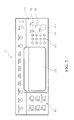
- FIG. 2 shows an operation/display unit
- FIGS. 3A to 3C show a transition of a "function-specific job management count setting" screen
- FIG. 4 shows a control operation of a job control unit.
- FIG. 1 illustrates a configuration of an image forming apparatus that may include a multifunction peripheral (MFP 1) according to the embodiment of the present disclosure.
- MFP 1 multifunction peripheral
- MFP 1 may include, as illustrated in FIG. 1 , central processing unit (CPU) 90 serving as a main control unit, read only memory (ROM) 91, and random access memory (RAM) 92.
- CPU central processing unit
- ROM read only memory
- RAM random access memory
- ROM 91 may store a job control program that causes CPU 90 to execute a job. Further, ROM 91 may store a program that causes CPU 90 to execute job processing of each of functions of copy, printer, facsimile (FAX), and PC transmission, and has the program read to thereby allow the respective functions to be carried out.
- FAX facsimile
- job as described herein is used to mean one or more tasks to be completed, possibly as instructed by a user of an image forming apparatus.
- a user of a copy machine may send instructions to the copy machine to complete a job for copying printed paper.
- the word "function" as described herein is used to mean one or more actions carried out by an item or machine to execute a job.
- copiers, printers, fax machines, personal computers, and/or mobile handsets, among other possibilities may carry out various functions to execute a job.
- the copy machine may carry out a function for receiving and/or reading the instructions to copy the printed paper. Further, the copy machine may also carry out a separate function for scanning and extracting data from the printed paper. Yet further, the copy machine may then carry out another function for making duplicate paper copies of the printed paper. Other possibilities may exist.
- RAM 92 is a memory that may be used as a work area in which CPU 90 temporarily spools data in executing those programs.
- MFP 1 may include, as illustrated in FIG. 1 , original reading unit 10, communication interface 11,operation/display unit 12, job input unit 13, image processing unit 14, output unit 15, job control unit 16, and FAX board interface 17.
- Original reading unit 10 may be a scanner that may read an original set on an original tray (not illustrated) to acquire image data in accordance with a copy operation or the like performed through operation/display unit 12.
- Original reading unit 10 may output the acquired image data to image processing unit 14.
- Communication interface 11 may be connected to a telephone line, a LAN, or the like, and may transmit and/or receive print data and FAX data to/from an external apparatus such as a personal computer, tablet computer, FAX apparatus, and/or cell phone, among other possibilities (not illustrated).
- an external apparatus such as a personal computer, tablet computer, FAX apparatus, and/or cell phone, among other possibilities (not illustrated).
- Operation/display unit 12 is disposed in an outer periphery of a top part of a main body (not illustrated) of MFP 1, and allows for one or more input operations to be performed by a user of MFP 1 and displays various screens for the user.
- Operation/display unit 12 may include, for example, as illustrated in FIG. 2 , operation part 121 that accepts an operation instruction from the user and display part 122 that displays information for the user.
- Operation part 121 may allow the user to perform various settings relating to an image output and an input operation for starting image processing.
- Operation part 121 may be provided with keys including: function selection keys K1 used to select the execution of the jobs such as copy, scanner, printing, and FAX; numerical keypad K2 that may be used to input numbers such as the number of prints and the number of print copies; start key K3 used to start the execution of the job after setting; clear key K4 used to cancel each kind of setting last performed through operation part 121; stop key K5 used to interrupt the started job; and reset key K6 used to cancel all the various settings and recover initial settings.
- keys may be added to operation part 121 for additional functionalities and in some instances, keys may be removed from operation part 121, among other possibilities (not illustrated).
- Display part 122 may operate using a liquid crystal display panel. In some embodiments, display part 122 may operate using touch-sense technology, which may send and/or receive instructions to/from CPU 90. Further, in some embodiments, display part 122 may display an operation status and an execution result of MFP 1, various setting values input through operation part 121, and/or a message for the user, among other possibilities.
- display part 122 may have a touch panel function (e.g., using touch-sense technology) for accepting a selection operation, and may also accept inputs of the various setting values corresponding to different kinds of operation screens.
- a touch panel function e.g., using touch-sense technology
- display part 122 may display a "function-specific job management count setting" screen (see FIGS. 3A to 3C ).
- a human finger touching each kind of key displayed on the screen may change the guaranteed value (guaranteed job count) on a function-to-function basis and/or a shared value (shared job count) of the number of simultaneously-executed jobs.
- job input unit 13 may receive inputs of the image data read by original reading unit 10 and job data such as the print data and the FAX data received via the communication interface 11, and outputs the same to image processing unit 14.
- Image processing unit 14 may interpret the job data input from job input unit 13, and perform image processing. For example, image processing unit 14 may perform color conversion processing, image density correction processing, and/or halftone screen processing, among other possibilities. This image processing may be performed for a job before or in conjunction with printing the image.
- Image processing unit 14 outputs the job subjected to the image processing to output unit 15.
- Output unit 15 outputs the image and data obtained through the above-mentioned image processing.
- Example embodiments for outputting the image and/or data may include a print engine used for printing an image, displaying a copy of the original image read by the scanner, producing an image from the received print data, and/or producing a FAX image, among other possibilities.
- Job control unit 16 performs different kinds of control based on the number of simultaneously-executed jobs.
- job control unit 16 may perform processing by rejecting a new job and notifying the user to that effect through display part 122 as a basic control operation. This can prevent overwork of the memory.
- job control unit 16 may control settings. For example, job control unit 16 may increase and/or reduce the function-to-function-basis guaranteed job count and the shared job count in accordance with various functions and the number of simultaneously-executed jobs.
- job control unit 16 may include functional blocks such as guaranteed job count setting unit 161, shared job count setting unit 162, and guaranteed job count changing unit 163.
- guaranteed job count setting unit 161 may set the guaranteed job count guaranteed as the number of simultaneously-executable jobs on a function-to-function basis.
- the number set as the guaranteed job count provides that a resource (e.g., memory) being used for the function is guaranteed to be available within a system. Further, the guaranteed job count represents the number of simultaneously-executable jobs that are always guaranteed to be executable without allowing the resource to be used for another function.
- a resource e.g., memory
- the guaranteed job count can be set for copying, PC transmission, printing, FAX transmission, and FAX reception.
- the guaranteed job count is restricted so that a total value of the guaranteed job counts for the respective functions is less than or equal to a specific permitted value. This is because there is a limitation on the resource such as the memory in which the jobs are spooled.
- the specificpermitted value is 470 jobs. If the respective guaranteed job counts are set to 10 jobs for the copy, 10 jobs for the PC transmission, 50 jobs for the printing, 200 jobs for the FAX transmission, and 100 jobs for the FAX reception, the total value thereof is 370 jobs, which enables the settings.
- the guaranteed job count can be set in advance at a time of manufacturing, or can be set by the user through communication interface 11 or operation/display unit 12.
- Shared job count setting unit 162 sets the shared job count that can be allocated according to the respective functions to reflect the number of simultaneously-executable jobs.
- a value obtained by subtracting the total value of the guaranteed job counts from the specific permitted value is set as the shared job count.
- the "shared job count" is a value obtained by subtracting the guaranteed job count allocated to the respective functions from a total number of simultaneously-executable jobs that can be executed with a given resource (e.g., the memory at its maximum capacity).
- guaranteed job count changing unit 163 increases the guaranteed job count corresponding to an arbitrary function within a range of the shared job count or reduces the guaranteed job count within a range of the original guaranteed job count.
- shared job count setting unit 162 subtracts the increased number from the shared job count. If the guaranteed job count corresponding to the arbitrary function is reduced, shared job count setting unit 162 adds the reduced number to the shared job count.
- Effective use of a resource such as memory is achieved by enabling the resource to be reserved as a shared resource while also enabling the resource to be reserved as a resource dedicated to each function.
- FAX board interface 17 transmits a signal indicating a mounted/removed state of a FAX board 17a to job control unit 16.
- Shared job count setting unit 162 and guaranteed job count changing unit 163 of job control unit 16 detect the mounted/removed state of FAX board 17a based on the signal received from FAX board interface 17.
- FIGS. 3A to 3C illustrate a transition of the "function-specific job management count setting" screen displayed by display part 122. Further, a setting screen is displayed when the guaranteed job count or the shared job count is changed.
- FIG. 3A illustrates the "function-specific job management count setting" screen first displayed at a time of activation or other such time.
- copy key f1, PC transmission key f2, print key f3, FAX transmission key f4, FAX reception key f5, share key f6, plus (+) key f7, minus (-) key f8, and confirm key f9 are displayed as operation keys on the "function-specific job management count setting" screen.
- boxes P1 to P5 for displaying the setting values of the function-specific guaranteed job counts and box P6 for displaying the setting value of the shared job count.
- the initial values of the respective guaranteed job counts are set to 10 jobs for the copy, 10 jobs for the PC transmission, 50 jobs for the printing, 200 jobs for the FAX transmission, and 100 jobs for the FAX reception and that the initial value of the shared job count is set to 100 jobs.
- the initial values of the respective guaranteed job counts are set to 10 jobs for the copy, 10 jobs for the PC transmission, 50 jobs for the printing, 200 jobs for the FAX transmission, and 100 jobs for the FAX reception and that the initial value of the shared job count is set to 100 jobs.
- other possibilities may also exist.
- the guaranteed job count changing unit changes the guaranteed job count corresponding to the FAX transmission from 200 to 100 and the guaranteed job count corresponding to the printing from 50 to 250, and the shared job count setting unit sets the shared job count to 0.
- the guaranteed job count corresponding to the arbitrary function can be increased or reduced, and this increase/reduction can be used to increase or reduce the shared job count.
- FIG. 4 illustrates the control operation of the job control unit.
- the job control unit determines a type of received job (Step S1), determines the number of jobs of the type in execution (including ones that have not been executed yet) (Step S2), and compares the number of jobs in execution with the number limit of the jobs of the type (Step S3).
- the "number limit (upper limit value)" of the subject jobs is defined based on the guaranteed job count corresponding to the function of the type of job and the shared job count.
- the excess amount is allocated from the shared job count. For this reason, when the excess amount is ⁇ jobs, the number limit is (300- ⁇ ) jobs.
- Step S4 the job control unit accepts the received job. Then the received job is executed (Step S4).
- the job control unit rejects the acceptance of the received job (Step S5). Note that, in this case, the job control unit informs the operation/display unit that the acceptance of the received job has failed, and display part 122 displays an error indicating the failure.
- the shared job count in association with the guaranteed job count, it is possible to obtain the upper limit value (number limit) of the number of simultaneously-executed jobs within the range whose minimum value is the guaranteed job count and whose maximum value is a value obtained by adding the guaranteed job count and the shared job count.
- the guaranteed job count is changed on a function-to-function basis, and the change allows the upper limit value to be changed.
- an image forming apparatus may be manufactured such that a specific function cannot be executed without mounting an optional device represented by the FAX board.
- an MFP that cannot perform the FAX transmission or the FAX reception without mounting FAX board 17a in FAX board interface 17.
- the shared job count setting unit 162 adds to the shared job count.
- the shared job count setting unit 162 adds to the shared job count the guaranteed job count typically set for a specific function when the optional device is properly mounted. Further, in some instances, the shared job count setting unit 162 adds to the shared job count the guaranteed job count that was previously set.
- the guaranteed job count changing unit 163 sets the guaranteed job count corresponding to the specific function to zero, or disables the guaranteed job count corresponding to the specific function. If the mounting of the optional device is detected, guaranteed job count changing unit 163 may add the added shared job count to the guaranteed job count corresponding to the specific function (zero), or may enable the guaranteed job count, which may have been disabled. At this time, shared job count setting unit 162 may subtract the added value from the shared job count.
- guaranteed job count changing unit 163 may distribute the guaranteed job count to the guaranteed job counts for other functions. For example, guaranteed job count changing unit 163 may distribute the guaranteed job count typically set for a specific function provided by mounting the optional device. Further, in some instances, guaranteed job count changing unit may distribute the guaranteed job count that was previously set.
- guaranteed job count changing unit 163 sets the guaranteed job count corresponding to the specific function to zero, or disables the guaranteed job count corresponding to the specific function that may no longer be available. If the mounting of the optional device is detected, guaranteed job count changing unit 163 may add the distributed guaranteed job count to the guaranteed job count corresponding to the specific function (zero), or may enable the guaranteed job count that has been disabled. At this time, guaranteed job count changing unit 163 may subtract the value that has been distributed from the guaranteed job counts for the other functions.
- the job control program operates as respective components of the image forming apparatus according to the above-described embodiments by being read and executed by a control unit (such as a CPU) of a computer of the image forming apparatus. Accordingly, the image forming apparatus performs job control such as changing of the upper limit value of the above-described number of simultaneously-executed jobs.
- a control unit such as a CPU
- the job control program is not limited to being stored in a ROM or a hard disk drive of the computer but can also be stored in a computer-readable recording medium, for example, an external storage device and/or a portable recording medium, among other possibilities.
- the external storage device includes an additional memory device which incorporates a recording medium such as a compact disc-read only memory (CD-ROM) and which is connected externally to the image forming apparatus.
- the portable recording medium represents a portable recording medium that can be inserted to a recording media drive (drive device), for example, a flexible disk, a memory card, and a magneto-optical disk.
- the program stored in the recording medium is loaded into a RAM or the like of the computer and executed by the CPU.
- the computer can use a communication line to download programs which are held by other computers onto the RAM or the external storage device which is owned by the computer itself.
- the downloaded programs are also executed by the CPU.
- the upper limit value of the number of simultaneously-executed jobs can be freely customized as an arbitrary value having a dynamic range. Therefore, it is possible to perform smooth execution of the job suitable for the use pattern and the use environment of the user.
- the above-described embodiments are in the case of taking an example of the MFP, but an information processing device such as a personal computer which has a plurality of functions and in which the resource such as the memory is shared can be also applied as the image forming apparatus according to the present disclosure.
- This can apply the present disclosure to a wide range of technical fields.
- the above-described embodiments are in the case of using a mode in which the shared job count is changed by guaranteed job count changing unit 163 performing the processing for changing the guaranteed job count, but the shared job count can be changed directly.
- a difference that has occurred due to the changing of the shared job count may be allocated as the guaranteed job count corresponding to the arbitrary function, or may be distributed as the guaranteed job counts corresponding to at least two functions.
Landscapes
- Engineering & Computer Science (AREA)
- Multimedia (AREA)
- Signal Processing (AREA)
- Facsimiles In General (AREA)
- Accessory Devices And Overall Control Thereof (AREA)
Applications Claiming Priority (1)
| Application Number | Priority Date | Filing Date | Title |
|---|---|---|---|
| JP2011204747A JP5544341B2 (ja) | 2011-09-20 | 2011-09-20 | 画像形成装置及びジョブ制御プログラム |
Publications (1)
| Publication Number | Publication Date |
|---|---|
| EP2574031A2 true EP2574031A2 (fr) | 2013-03-27 |
Family
ID=47290571
Family Applications (1)
| Application Number | Title | Priority Date | Filing Date |
|---|---|---|---|
| EP12185170A Withdrawn EP2574031A2 (fr) | 2011-09-20 | 2012-09-20 | Appareil de formation d'image qui commande le nombre de tâches pouvant être exécutées simultanément |
Country Status (4)
| Country | Link |
|---|---|
| US (1) | US8891103B2 (fr) |
| EP (1) | EP2574031A2 (fr) |
| JP (1) | JP5544341B2 (fr) |
| CN (1) | CN103024235B (fr) |
Cited By (1)
| Publication number | Priority date | Publication date | Assignee | Title |
|---|---|---|---|---|
| EP2953336A3 (fr) * | 2014-06-02 | 2016-01-27 | Samsung Electronics Co., Ltd. | Appareil de formation d'image, appareil mobile et procédé de commande d'impression |
Families Citing this family (3)
| Publication number | Priority date | Publication date | Assignee | Title |
|---|---|---|---|---|
| US9465645B1 (en) * | 2014-06-25 | 2016-10-11 | Amazon Technologies, Inc. | Managing backlogged tasks |
| JP2016018468A (ja) * | 2014-07-10 | 2016-02-01 | 富士ゼロックス株式会社 | 情報処理装置及びプログラム |
| US10366358B1 (en) | 2014-12-19 | 2019-07-30 | Amazon Technologies, Inc. | Backlogged computing work exchange |
Family Cites Families (3)
| Publication number | Priority date | Publication date | Assignee | Title |
|---|---|---|---|---|
| JPH10257281A (ja) * | 1997-03-12 | 1998-09-25 | Minolta Co Ltd | 画像形成装置 |
| JP2007164481A (ja) * | 2005-12-14 | 2007-06-28 | Casio Comput Co Ltd | ジョブスプール実行制御装置 |
| JP5415750B2 (ja) * | 2008-11-28 | 2014-02-12 | キヤノン株式会社 | 情報処理装置、情報処理方法、プログラム、並びに、情報処理システム |
-
2011
- 2011-09-20 JP JP2011204747A patent/JP5544341B2/ja not_active Expired - Fee Related
-
2012
- 2012-08-30 CN CN201210323124.4A patent/CN103024235B/zh not_active Expired - Fee Related
- 2012-09-20 EP EP12185170A patent/EP2574031A2/fr not_active Withdrawn
- 2012-09-20 US US13/623,761 patent/US8891103B2/en not_active Expired - Fee Related
Non-Patent Citations (1)
| Title |
|---|
| None |
Cited By (1)
| Publication number | Priority date | Publication date | Assignee | Title |
|---|---|---|---|---|
| EP2953336A3 (fr) * | 2014-06-02 | 2016-01-27 | Samsung Electronics Co., Ltd. | Appareil de formation d'image, appareil mobile et procédé de commande d'impression |
Also Published As
| Publication number | Publication date |
|---|---|
| JP5544341B2 (ja) | 2014-07-09 |
| CN103024235A (zh) | 2013-04-03 |
| CN103024235B (zh) | 2015-08-05 |
| US20130070283A1 (en) | 2013-03-21 |
| JP2013066123A (ja) | 2013-04-11 |
| US8891103B2 (en) | 2014-11-18 |
Similar Documents
| Publication | Publication Date | Title |
|---|---|---|
| JP5447476B2 (ja) | 画像読取装置、画像読取システム及び画像読取プログラム | |
| US9235793B2 (en) | Information processing apparatus, storage medium, and information processing system | |
| JP5696411B2 (ja) | 画像形成装置、画面表示方法及びプログラム | |
| JP6330349B2 (ja) | 表示制御装置、表示システム、操作表示装置、プログラム | |
| US10129426B2 (en) | Image forming apparatus having display screen with position configurable icons, information processing method, and computer-readable recording medium | |
| US8891103B2 (en) | Image forming apparatus which controls the number of jobs that can be executed simultaneously | |
| JP4736774B2 (ja) | 画像処理プログラム、画像処理方法、画像処理装置および画像処理システム | |
| US20170060644A1 (en) | Image processing apparatus, control task allocation method, and recording medium | |
| JP5355290B2 (ja) | ジョブ処理装置、ジョブ処理装置の制御方法、及びプログラム | |
| JP2011177966A (ja) | 画像形成装置、画像形成システム及び画像形成装置の制御方法 | |
| JP2009075451A (ja) | 画像形成装置 | |
| JP5805507B2 (ja) | 画像処理装置及びセットアップ方法 | |
| JP2013125455A (ja) | 画像形成装置 | |
| JP2024002660A (ja) | 画像読取装置および画像読取方法 | |
| JP2013061750A (ja) | 画像形成装置及びジョブ制御プログラム | |
| JP5218693B2 (ja) | 画像形成装置及びリソースコスト出力方法 | |
| JP5669709B2 (ja) | 動作制御プログラム及び情報処理装置 | |
| US9270851B2 (en) | Image forming apparatus method and storage medium storing program for controlling display when the image forming appratus returns to an active state from a power-saving state | |
| JP2013168023A (ja) | 画像形成装置、及び画像形成装置の制御プログラム | |
| JP2020069777A (ja) | 画像処理装置 | |
| JP2012094054A (ja) | 操作装置及び画像形成装置 | |
| JP2006186777A (ja) | 画像形成装置及び画像形成プログラム | |
| JP2008245191A (ja) | 画像形成装置および画像形成装置の履歴制御プログラム | |
| JP2022173842A (ja) | 画像形成装置 | |
| JP2006081093A (ja) | 画像処理装置およびその制御方法および制御プログラム |
Legal Events
| Date | Code | Title | Description |
|---|---|---|---|
| PUAI | Public reference made under article 153(3) epc to a published international application that has entered the european phase |
Free format text: ORIGINAL CODE: 0009012 |
|
| 17P | Request for examination filed |
Effective date: 20120920 |
|
| AK | Designated contracting states |
Kind code of ref document: A2 Designated state(s): AL AT BE BG CH CY CZ DE DK EE ES FI FR GB GR HR HU IE IS IT LI LT LU LV MC MK MT NL NO PL PT RO RS SE SI SK SM TR |
|
| AX | Request for extension of the european patent |
Extension state: BA ME |
|
| STAA | Information on the status of an ep patent application or granted ep patent |
Free format text: STATUS: THE APPLICATION HAS BEEN WITHDRAWN |
|
| 18W | Application withdrawn |
Effective date: 20160728 |