EP2574227B1 - Moissonneuse automobile - Google Patents
Moissonneuse automobile Download PDFInfo
- Publication number
- EP2574227B1 EP2574227B1 EP20120175222 EP12175222A EP2574227B1 EP 2574227 B1 EP2574227 B1 EP 2574227B1 EP 20120175222 EP20120175222 EP 20120175222 EP 12175222 A EP12175222 A EP 12175222A EP 2574227 B1 EP2574227 B1 EP 2574227B1
- Authority
- EP
- European Patent Office
- Prior art keywords
- brake
- self
- propelled harvester
- drum
- harvester
- Prior art date
- Legal status (The legal status is an assumption and is not a legal conclusion. Google has not performed a legal analysis and makes no representation as to the accuracy of the status listed.)
- Active
Links
Images


Classifications
-
- A—HUMAN NECESSITIES
- A01—AGRICULTURE; FORESTRY; ANIMAL HUSBANDRY; HUNTING; TRAPPING; FISHING
- A01D—HARVESTING; MOWING
- A01D41/00—Combines, i.e. harvesters or mowers combined with threshing devices
- A01D41/12—Details of combines
- A01D41/14—Mowing tables
- A01D41/142—Header drives
-
- A—HUMAN NECESSITIES
- A01—AGRICULTURE; FORESTRY; ANIMAL HUSBANDRY; HUNTING; TRAPPING; FISHING
- A01D—HARVESTING; MOWING
- A01D75/00—Accessories for harvesters or mowers
- A01D75/18—Safety devices for parts of the machines
- A01D75/187—Removing foreign objects
-
- A—HUMAN NECESSITIES
- A01—AGRICULTURE; FORESTRY; ANIMAL HUSBANDRY; HUNTING; TRAPPING; FISHING
- A01F—PROCESSING OF HARVESTED PRODUCE; HAY OR STRAW PRESSES; DEVICES FOR STORING AGRICULTURAL OR HORTICULTURAL PRODUCE
- A01F12/00—Parts or details of threshing apparatus
- A01F12/10—Feeders
- A01F12/16—Safety devices
-
- A—HUMAN NECESSITIES
- A01—AGRICULTURE; FORESTRY; ANIMAL HUSBANDRY; HUNTING; TRAPPING; FISHING
- A01F—PROCESSING OF HARVESTED PRODUCE; HAY OR STRAW PRESSES; DEVICES FOR STORING AGRICULTURAL OR HORTICULTURAL PRODUCE
- A01F29/00—Cutting apparatus specially adapted for cutting hay, straw or the like
- A01F29/09—Details
- A01F29/16—Safety devices, e.g. emergency brake arrangements
Definitions
- the present invention relates to a self-propelled harvesting machine according to the preamble of claim 1.
- Self-propelled harvesting machines are equipped with a collection device arranged in the front region of the harvesting machine, which serves to feed harvested crop picked up by a harvesting device attachable to the collection device into the harvesting machine for further processing thereof.
- the Erntegutabilityvorides is driven by a arranged on the feeder drive shaft and braked by a braking device.
- Such a harvester is from the DE 199 40 467 A1 known.
- an agricultural harvesting machine having a feeder to which a Erntegutagevoriques is attachable.
- the drive of the inclined conveyor as well as the Erntegutabilityvoriques takes place through the harvester and is separated therefrom by a coupling which is arranged at a first end of the upper sprocket of the inclined conveyor.
- a pulley is fixed, which drives a belt pulley on a lower sprocket of the inclined conveyor by means of a belt.
- the lower sprocket is associated with a hydraulically actuated disc brake, which causes a shutdown of Erntegut applicationvortechnisch.
- the braking device is designed as a drum brake with a brake drum, in which at least one additional function is integrated.
- the closed construction of a drum brake prevents the occurrence of flying sparks, which can significantly reduce the risk of fire.
- a drum brake is less susceptible to corrosion.
- the additional function in the reversing function of the collection device and the Erntegutagevoriques exist.
- the reversing function of the drive of the collection device and the Erntegutavoriques is necessary in order to be able to eliminate this in a Gutstau occurring in the Erntegutavorplatz and / or the collection device.
- the brake device may have a bearing flange, which serves as a shaft bearing and the inclusion of the components of the braking device.
- the constructive core of the brake device forming bearing flange contributes significantly to the desired functional integration and allows universal applicability of the braking device on both combine harvesters and forage harvesters.
- the brake device can be controlled by a hydraulically loadable brake cylinder.
- a quick response of the braking device can be achieved.
- the integration in the already existing on the feeder hydraulic circuit is also inexpensive.
- a gear formed on the brake drum can be provided as reversing drive, which can be brought into engagement with a pinion actuatable by a hydraulic cylinder for the reversing function.
- the reversing function is used in the event of a blockage of the harvesting material receiving device and / or the collection device in order to convey out crop material which blocks the harvested crop receiving device and / or the collection device.
- the brake device can be arranged at the end of a drive train driving the intake device.
- the arrangement should take place in the immediate vicinity of the units to be braked.
- a quick and direct braking of the collection device and the Erntegutavoriques can be achieved.
- the load on the drive train is significantly reduced by this arrangement, since an introduction of shear forces is eliminated.
- the additional function in the embodiment of the brake drum can consist of a drive element.
- the drive element may be designed as a molded onto the brake drum pulley.
- the in Fig. 1 Combine 1 shown schematically consists of a support frame connected to the chassis, on which a multi-part machine housing 22 is attached.
- a closed cab 23 is arranged in the front area.
- the combine harvester 1 picks up a crop collecting device in the form of a grain cutting unit 2, which is connected in a manner known per se to a collection device in the form of an inclined conveyor 4 on the combine harvester 1.
- the cross conveyor 3 of the cutting unit 2 passes the crop to the feeder 4, which passes the crop through a revolving chain conveyor 5 in its top-rear region to the threshing unit 6 of the combine 1.
- the crop is passed between the threshing drum 7 and a threshing concave 8 which at least partly covers it and is separated into at least two partial streams 9, 10.
- the first partial flow 9 consists essentially of grains, short straw and chaff and is fed via a preparation tray 11 directly to a cleaning device 13 consisting of different screen planes 12.
- the cleaning device 13 also adopts a cleaning fan 14, which generates an airflow passing through the wire planes 12.
- FIG. 2 shows a side view of the feed device of the combine harvester 1 designed as an inclined conveyor 4 according to Fig. 1 ,
- the inclined conveyor 4 is arranged with one end on the combine 1 while the opposite end of the recording of the cutting unit 2 is used.
- the inclined conveyor 4 driven shafts which are respectively arranged in end portions of the inclined conveyor 4 transverse to its longitudinal axis.
- the position of a first, the drive of the inclined conveyor 4 serving shaft through an opening 30 in the side wall of the inclined conveyor 4 is indicated.
- the opposite end region is located one of the reversing of the inclined conveyor 4 and the cutting unit 2 serving reversing device 31.
- the reversing device 31 serving to perform the reversing function comprises a lever assembly 32 which is hydraulically actuated, and a gear 51, which in Fig. 4 is shown.
- the reversing device 31 interacts with its operation with a braking device 33, in which at least one additional function is integrated.
- a braking device 33 in which at least one additional function is integrated.
- a reversing of the inclined conveyor 4 and the cutting unit 2 to achieve a Gutstau reach.
- the drum brake 34 is as shown in the detail view Fig. 3 can be actuated by a hydraulic actuator 37 operable to brake the drive of the cutting unit 2 serving shaft as quickly as possible, for example, if foreign objects could be absorbed by the cutting unit 2, which could lead to damage to the cutting unit 2 or to the working elements of the combine 1.
- the arrangement of the braking device 33 in the immediate vicinity of the cutting unit 2 is advantageous in that the cutting unit 2 can be braked faster and more directly.
- Fig. 4 is a sectional view of the braking device 33 along the line II-II shown. This view is the internal structure of the brake device 33 can be seen.
- the braking device 33 is arranged by means of a bearing flange 39 on a transverse to the longitudinal direction of the inclined conveyor 4 extending shaft 38.
- the bearing flange 39 is used in addition to the arrangement of the braking device 33 on the shaft 38 and the inclusion of the individual components of the braking device 33, such as the drum brake 34, and also forms the brake drum 35 and the formed on the brake drum 35 gear 36 from.
- the integration of many different functionalities in a single component leads to a high functional density and, consequently, to a space-saving design. Along with this, the assembly effort also drops.
- the illustration shows a gear 51, which can be brought by the indicated hydraulic drive with the gear 36 on the brake drum 35 in engagement to achieve reversing the drive of the inclined conveyor 4 and the cutting unit 2 when a crop accumulation occurs in them.
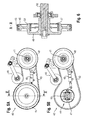
- the representations in the Figs. 5A and 5B each show a side view of a drive device 40 for a collection device of a self-propelled forage harvester, which can also be used on a combine harvester.
- Guided by two pulleys 42, 45 runs a belt 43, which serves to transmit a torque to the aggregates of the collection device.
- the torque is provided by a motor arranged in the rear region of the self-propelled forage harvester and transmitted via a first, not shown belt drive on a shaft 41 carrying the cutterhead and from there via the attached to the shaft 41 pulley 42 to the collection device.
- the belt 43 is acted upon by a tensioning device 46 provided with a hydraulically actuable pressure roller.
- the tensioning device 46 is used as a clutch to release the bias applied to the belt 43 from the tension pulley in the case of a quick stop of the drive device 40, whereby the belt 43 can slip.
- a braking device 44 is visible, which includes the pulley 45 as a component.
- the brake device 44 is designed as a drum brake 47, on the brake drum, the pulley 45 is formed.
- the drum brake 47 is, as already above has been described, hydraulically actuated.
- a hydraulic actuatable actuator 48 is arranged on the intake device of the forage harvester.
- the representation according to Fig. 6 shows a sectional view taken along the line VV according to Fig. 5A , From this illustration, the internal structure of the brake device 44 with integrated additional function can be seen.
- the brake device 44 is supported on a shaft 50 supported by a bearing flange 49.
- the bearing flange 49 also carries all components of the braking device 44 and forms its brake drum 52 in this exemplary embodiment.
- the bearing flange 49 differs from that bearing flange 39, the part of the braking device 33 on the inclined conveyor 4 of the combine harvester 1 is characterized in that a pulley 45 is formed on the brake drum 52 instead of a formed on the brake drum 35 gear 36, to take over the additional function of a drive means.
Landscapes
- Life Sciences & Earth Sciences (AREA)
- Environmental Sciences (AREA)
- Harvester Elements (AREA)
Claims (9)
- Machine de récolte automotrice (1) comprenant un dispositif d'alimentation (4) qui est disposé dans la zone avant de la machine de récolte (1) et sur lequel peut être monté un dispositif récepteur de produit récolté (2), lequel peut être entraîné par un arbre d'entraînement disposé sur le dispositif d'alimentation (4) et peut être freiné par un dispositif de freinage (33, 34), caractérisée en ce que le dispositif de freinage (33, 34) est conformé en frein à tambour (34, 47) avec un tambour de frein (35, 52) auquel est intégrée au moins une fonction supplémentaire.
- Machine de récolte automotrice (1) selon la revendication 1, caractérisée en ce que la fonction supplémentaire réside dans la fonction réversible du dispositif récepteur de produit récolté (2) et du dispositif d'alimentation (4).
- Machine de récolte automotrice (1) selon une des revendications 1 ou 2, caractérisée en ce que le dispositif de freinage (33, 34) comporte une bride de montage (39, 49) qui sert de palier d'arbre et à recevoir les composants du dispositif de freinage (33, 44).
- Machine de récolte automotrice (1) selon la revendication 3, caractérisée en ce que la bride de montage (39, 48) forme le tambour de frein (35, 52) du dispositif de freinage (33, 44).
- Machine de récolte automotrice (1) selon une des revendications 1 à 4, caractérisée en ce que le dispositif de freinage (33, 44) est commandable par l'intermédiaire d'un actionneur à sollicitation hydraulique (37).
- Machine de récolte automotrice (1) selon une des revendications 2 à 5, caractérisée en ce que, pour réaliser la fonction réversible, il est prévu une roue dentée (36) qui est moulée sur le tambour de frein (35) et qui, pour la réversion, peut être amenée en prise avec une roue dentée (51) actionnable par l'intermédiaire d'un moyen d'entraînement hydraulique.
- Machine de récolte automotrice (1) selon une des revendications 1 à 6, caractérisé en ce que le dispositif de freinage (33, 44) est disposé à l'extrémité d'une chaîne de transmission entraînant le dispositif d'alimentation (4).
- Machine de récolte automotrice (1) selon la revendication 1, caractérisée en ce que la fonction supplémentaire réside dans la conception du tambour de frein (52) sous la forme d'un élément d'entraînement (45).
- Machine de récolte automotrice selon la revendication 8, caractérisée en ce que l'élément d'entraînement est conçu sous la forme d'une poulie à courroie (45) moulée sur le tambour de frein (52).
Applications Claiming Priority (1)
| Application Number | Priority Date | Filing Date | Title |
|---|---|---|---|
| DE201110054095 DE102011054095A1 (de) | 2011-09-30 | 2011-09-30 | Selbstfahrende Erntemaschine |
Publications (2)
| Publication Number | Publication Date |
|---|---|
| EP2574227A1 EP2574227A1 (fr) | 2013-04-03 |
| EP2574227B1 true EP2574227B1 (fr) | 2015-02-25 |
Family
ID=46465115
Family Applications (1)
| Application Number | Title | Priority Date | Filing Date |
|---|---|---|---|
| EP20120175222 Active EP2574227B1 (fr) | 2011-09-30 | 2012-07-06 | Moissonneuse automobile |
Country Status (2)
| Country | Link |
|---|---|
| EP (1) | EP2574227B1 (fr) |
| DE (1) | DE102011054095A1 (fr) |
Families Citing this family (1)
| Publication number | Priority date | Publication date | Assignee | Title |
|---|---|---|---|---|
| US10426089B2 (en) * | 2016-07-06 | 2019-10-01 | Tribine Industries Llc | Feeder having lateral tilt for an agricultural harvesting combine |
Family Cites Families (2)
| Publication number | Priority date | Publication date | Assignee | Title |
|---|---|---|---|---|
| DE19940467A1 (de) | 1998-08-26 | 2001-03-08 | Klaus Klee | Erntevorsatz für eine Erntemaschine |
| DE19929987A1 (de) * | 1999-06-30 | 2001-01-04 | Claas Selbstfahr Erntemasch | Landwirtschaftliche Erntemaschine |
-
2011
- 2011-09-30 DE DE201110054095 patent/DE102011054095A1/de not_active Withdrawn
-
2012
- 2012-07-06 EP EP20120175222 patent/EP2574227B1/fr active Active
Also Published As
| Publication number | Publication date |
|---|---|
| EP2574227A1 (fr) | 2013-04-03 |
| DE102011054095A1 (de) | 2013-04-04 |
Similar Documents
| Publication | Publication Date | Title |
|---|---|---|
| DE69909883T2 (de) | Erntemaschine mit Volumendurchflussmengesensor des Ernteguts | |
| EP2014149B1 (fr) | Tambour rotatif de séparation pour une batteuse à plusieurs cylindres | |
| EP3391725A1 (fr) | Ensemble à convoyeur à vis pour une moissonneuse-batteuse | |
| EP2676538A1 (fr) | Batteuse tangentielle dotée d'un tambour de transport et d'un tambour de battage ou de séparation | |
| EP2839729B1 (fr) | Moissonneuse-batteuse équipée d'un dispositif de hache-paille | |
| EP1038429A1 (fr) | Dispositif pour mesurer la quantité des grains dans le dispositif de renvoi de résidus d'une moissonneuse-batteuse | |
| DE102013214984A1 (de) | Anordnung zur Verlustmessung in einem Mähdrescher | |
| EP1226747B1 (fr) | Tambour avec éléments entraíneurs interchangeables | |
| DE3533773A1 (de) | Selbstfahrender feldhaecksler | |
| EP4124234A1 (fr) | Transporteur incliné et machine de récolte autonome dotée d'un transporteur incliné | |
| DD246694A5 (de) | Selbstfahrender maehdrescher | |
| EP4059339B1 (fr) | Engin d'abattage-façonnage | |
| BE1023463B1 (de) | Erntevorsatz mit seitlicher Abdeckung | |
| EP2574227B1 (fr) | Moissonneuse automobile | |
| EP3797577B1 (fr) | Moissonneuse-batteuse pourvue de capteur de grains restants | |
| EP4470358A1 (fr) | Moissonneuse-batteuse automotrice avec une tête de récolte | |
| DE2610600A1 (de) | Maehdrescher der axialfluss-bauart | |
| DE102011088543B4 (de) | Mähdrescher mit einer zwischen der Drescheinrichtung und der Reinigung angeordneten Nachdrescheinrichtung | |
| DE10232802A1 (de) | Erntemaschine | |
| DE102013202050A1 (de) | Dreschwerk mit einer Wendetrommel und einer Abstreifrolle | |
| EP0095747B1 (fr) | Moissonneuse-batteuse avec un ensemble pour battre | |
| EP2574231B1 (fr) | Moissonneuse-batteuse | |
| DE19926827C2 (de) | Antrieb für eine Kolbensammelpresse für landwirtschaftliche Erntegüter | |
| EP1712120B1 (fr) | Goulotte d'évacuation pour une faucheuse-hacheuse | |
| DE102023132967A1 (de) | Mähdrescher |
Legal Events
| Date | Code | Title | Description |
|---|---|---|---|
| PUAI | Public reference made under article 153(3) epc to a published international application that has entered the european phase |
Free format text: ORIGINAL CODE: 0009012 |
|
| AK | Designated contracting states |
Kind code of ref document: A1 Designated state(s): AL AT BE BG CH CY CZ DE DK EE ES FI FR GB GR HR HU IE IS IT LI LT LU LV MC MK MT NL NO PL PT RO RS SE SI SK SM TR |
|
| AX | Request for extension of the european patent |
Extension state: BA ME |
|
| 17P | Request for examination filed |
Effective date: 20131004 |
|
| RBV | Designated contracting states (corrected) |
Designated state(s): AL AT BE BG CH CY CZ DE DK EE ES FI FR GB GR HR HU IE IS IT LI LT LU LV MC MK MT NL NO PL PT RO RS SE SI SK SM TR |
|
| GRAP | Despatch of communication of intention to grant a patent |
Free format text: ORIGINAL CODE: EPIDOSNIGR1 |
|
| INTG | Intention to grant announced |
Effective date: 20141112 |
|
| GRAS | Grant fee paid |
Free format text: ORIGINAL CODE: EPIDOSNIGR3 |
|
| GRAA | (expected) grant |
Free format text: ORIGINAL CODE: 0009210 |
|
| AK | Designated contracting states |
Kind code of ref document: B1 Designated state(s): AL AT BE BG CH CY CZ DE DK EE ES FI FR GB GR HR HU IE IS IT LI LT LU LV MC MK MT NL NO PL PT RO RS SE SI SK SM TR |
|
| REG | Reference to a national code |
Ref country code: GB Ref legal event code: FG4D Free format text: NOT ENGLISH |
|
| REG | Reference to a national code |
Ref country code: CH Ref legal event code: EP |
|
| REG | Reference to a national code |
Ref country code: IE Ref legal event code: FG4D Free format text: LANGUAGE OF EP DOCUMENT: GERMAN |
|
| REG | Reference to a national code |
Ref country code: DE Ref legal event code: R096 Ref document number: 502012002327 Country of ref document: DE Effective date: 20150409 |
|
| REG | Reference to a national code |
Ref country code: AT Ref legal event code: REF Ref document number: 711105 Country of ref document: AT Kind code of ref document: T Effective date: 20150415 |
|
| REG | Reference to a national code |
Ref country code: NL Ref legal event code: VDEP Effective date: 20150225 |
|
| REG | Reference to a national code |
Ref country code: LT Ref legal event code: MG4D |
|
| PG25 | Lapsed in a contracting state [announced via postgrant information from national office to epo] |
Ref country code: SE Free format text: LAPSE BECAUSE OF FAILURE TO SUBMIT A TRANSLATION OF THE DESCRIPTION OR TO PAY THE FEE WITHIN THE PRESCRIBED TIME-LIMIT Effective date: 20150225 Ref country code: LT Free format text: LAPSE BECAUSE OF FAILURE TO SUBMIT A TRANSLATION OF THE DESCRIPTION OR TO PAY THE FEE WITHIN THE PRESCRIBED TIME-LIMIT Effective date: 20150225 Ref country code: FI Free format text: LAPSE BECAUSE OF FAILURE TO SUBMIT A TRANSLATION OF THE DESCRIPTION OR TO PAY THE FEE WITHIN THE PRESCRIBED TIME-LIMIT Effective date: 20150225 Ref country code: NO Free format text: LAPSE BECAUSE OF FAILURE TO SUBMIT A TRANSLATION OF THE DESCRIPTION OR TO PAY THE FEE WITHIN THE PRESCRIBED TIME-LIMIT Effective date: 20150525 Ref country code: HR Free format text: LAPSE BECAUSE OF FAILURE TO SUBMIT A TRANSLATION OF THE DESCRIPTION OR TO PAY THE FEE WITHIN THE PRESCRIBED TIME-LIMIT Effective date: 20150225 Ref country code: ES Free format text: LAPSE BECAUSE OF FAILURE TO SUBMIT A TRANSLATION OF THE DESCRIPTION OR TO PAY THE FEE WITHIN THE PRESCRIBED TIME-LIMIT Effective date: 20150225 |
|
| PG25 | Lapsed in a contracting state [announced via postgrant information from national office to epo] |
Ref country code: RS Free format text: LAPSE BECAUSE OF FAILURE TO SUBMIT A TRANSLATION OF THE DESCRIPTION OR TO PAY THE FEE WITHIN THE PRESCRIBED TIME-LIMIT Effective date: 20150225 Ref country code: GR Free format text: LAPSE BECAUSE OF FAILURE TO SUBMIT A TRANSLATION OF THE DESCRIPTION OR TO PAY THE FEE WITHIN THE PRESCRIBED TIME-LIMIT Effective date: 20150526 Ref country code: LV Free format text: LAPSE BECAUSE OF FAILURE TO SUBMIT A TRANSLATION OF THE DESCRIPTION OR TO PAY THE FEE WITHIN THE PRESCRIBED TIME-LIMIT Effective date: 20150225 Ref country code: IS Free format text: LAPSE BECAUSE OF FAILURE TO SUBMIT A TRANSLATION OF THE DESCRIPTION OR TO PAY THE FEE WITHIN THE PRESCRIBED TIME-LIMIT Effective date: 20150625 |
|
| PG25 | Lapsed in a contracting state [announced via postgrant information from national office to epo] |
Ref country code: NL Free format text: LAPSE BECAUSE OF FAILURE TO SUBMIT A TRANSLATION OF THE DESCRIPTION OR TO PAY THE FEE WITHIN THE PRESCRIBED TIME-LIMIT Effective date: 20150225 |
|
| PG25 | Lapsed in a contracting state [announced via postgrant information from national office to epo] |
Ref country code: EE Free format text: LAPSE BECAUSE OF FAILURE TO SUBMIT A TRANSLATION OF THE DESCRIPTION OR TO PAY THE FEE WITHIN THE PRESCRIBED TIME-LIMIT Effective date: 20150225 Ref country code: CZ Free format text: LAPSE BECAUSE OF FAILURE TO SUBMIT A TRANSLATION OF THE DESCRIPTION OR TO PAY THE FEE WITHIN THE PRESCRIBED TIME-LIMIT Effective date: 20150225 Ref country code: RO Free format text: LAPSE BECAUSE OF FAILURE TO SUBMIT A TRANSLATION OF THE DESCRIPTION OR TO PAY THE FEE WITHIN THE PRESCRIBED TIME-LIMIT Effective date: 20150225 Ref country code: DK Free format text: LAPSE BECAUSE OF FAILURE TO SUBMIT A TRANSLATION OF THE DESCRIPTION OR TO PAY THE FEE WITHIN THE PRESCRIBED TIME-LIMIT Effective date: 20150225 Ref country code: SK Free format text: LAPSE BECAUSE OF FAILURE TO SUBMIT A TRANSLATION OF THE DESCRIPTION OR TO PAY THE FEE WITHIN THE PRESCRIBED TIME-LIMIT Effective date: 20150225 |
|
| REG | Reference to a national code |
Ref country code: DE Ref legal event code: R097 Ref document number: 502012002327 Country of ref document: DE |
|
| PG25 | Lapsed in a contracting state [announced via postgrant information from national office to epo] |
Ref country code: PL Free format text: LAPSE BECAUSE OF FAILURE TO SUBMIT A TRANSLATION OF THE DESCRIPTION OR TO PAY THE FEE WITHIN THE PRESCRIBED TIME-LIMIT Effective date: 20150225 |
|
| PG25 | Lapsed in a contracting state [announced via postgrant information from national office to epo] |
Ref country code: IT Free format text: LAPSE BECAUSE OF FAILURE TO SUBMIT A TRANSLATION OF THE DESCRIPTION OR TO PAY THE FEE WITHIN THE PRESCRIBED TIME-LIMIT Effective date: 20150225 |
|
| PLBE | No opposition filed within time limit |
Free format text: ORIGINAL CODE: 0009261 |
|
| STAA | Information on the status of an ep patent application or granted ep patent |
Free format text: STATUS: NO OPPOSITION FILED WITHIN TIME LIMIT |
|
| 26N | No opposition filed |
Effective date: 20151126 |
|
| PG25 | Lapsed in a contracting state [announced via postgrant information from national office to epo] |
Ref country code: SI Free format text: LAPSE BECAUSE OF FAILURE TO SUBMIT A TRANSLATION OF THE DESCRIPTION OR TO PAY THE FEE WITHIN THE PRESCRIBED TIME-LIMIT Effective date: 20150225 Ref country code: MC Free format text: LAPSE BECAUSE OF FAILURE TO SUBMIT A TRANSLATION OF THE DESCRIPTION OR TO PAY THE FEE WITHIN THE PRESCRIBED TIME-LIMIT Effective date: 20150225 |
|
| REG | Reference to a national code |
Ref country code: CH Ref legal event code: PL |
|
| PG25 | Lapsed in a contracting state [announced via postgrant information from national office to epo] |
Ref country code: LU Free format text: LAPSE BECAUSE OF FAILURE TO SUBMIT A TRANSLATION OF THE DESCRIPTION OR TO PAY THE FEE WITHIN THE PRESCRIBED TIME-LIMIT Effective date: 20150706 |
|
| REG | Reference to a national code |
Ref country code: IE Ref legal event code: MM4A |
|
| PG25 | Lapsed in a contracting state [announced via postgrant information from national office to epo] |
Ref country code: CH Free format text: LAPSE BECAUSE OF NON-PAYMENT OF DUE FEES Effective date: 20150731 Ref country code: LI Free format text: LAPSE BECAUSE OF NON-PAYMENT OF DUE FEES Effective date: 20150731 |
|
| REG | Reference to a national code |
Ref country code: FR Ref legal event code: PLFP Year of fee payment: 5 |
|
| PG25 | Lapsed in a contracting state [announced via postgrant information from national office to epo] |
Ref country code: IE Free format text: LAPSE BECAUSE OF NON-PAYMENT OF DUE FEES Effective date: 20150706 |
|
| GBPC | Gb: european patent ceased through non-payment of renewal fee |
Effective date: 20160706 |
|
| PG25 | Lapsed in a contracting state [announced via postgrant information from national office to epo] |
Ref country code: MT Free format text: LAPSE BECAUSE OF FAILURE TO SUBMIT A TRANSLATION OF THE DESCRIPTION OR TO PAY THE FEE WITHIN THE PRESCRIBED TIME-LIMIT Effective date: 20150225 |
|
| PG25 | Lapsed in a contracting state [announced via postgrant information from national office to epo] |
Ref country code: SM Free format text: LAPSE BECAUSE OF FAILURE TO SUBMIT A TRANSLATION OF THE DESCRIPTION OR TO PAY THE FEE WITHIN THE PRESCRIBED TIME-LIMIT Effective date: 20150225 Ref country code: GB Free format text: LAPSE BECAUSE OF NON-PAYMENT OF DUE FEES Effective date: 20160706 Ref country code: HU Free format text: LAPSE BECAUSE OF FAILURE TO SUBMIT A TRANSLATION OF THE DESCRIPTION OR TO PAY THE FEE WITHIN THE PRESCRIBED TIME-LIMIT; INVALID AB INITIO Effective date: 20120706 Ref country code: BG Free format text: LAPSE BECAUSE OF FAILURE TO SUBMIT A TRANSLATION OF THE DESCRIPTION OR TO PAY THE FEE WITHIN THE PRESCRIBED TIME-LIMIT Effective date: 20150225 |
|
| PG25 | Lapsed in a contracting state [announced via postgrant information from national office to epo] |
Ref country code: CY Free format text: LAPSE BECAUSE OF FAILURE TO SUBMIT A TRANSLATION OF THE DESCRIPTION OR TO PAY THE FEE WITHIN THE PRESCRIBED TIME-LIMIT Effective date: 20150225 |
|
| REG | Reference to a national code |
Ref country code: FR Ref legal event code: PLFP Year of fee payment: 6 |
|
| PG25 | Lapsed in a contracting state [announced via postgrant information from national office to epo] |
Ref country code: TR Free format text: LAPSE BECAUSE OF FAILURE TO SUBMIT A TRANSLATION OF THE DESCRIPTION OR TO PAY THE FEE WITHIN THE PRESCRIBED TIME-LIMIT Effective date: 20150225 |
|
| PG25 | Lapsed in a contracting state [announced via postgrant information from national office to epo] |
Ref country code: MK Free format text: LAPSE BECAUSE OF FAILURE TO SUBMIT A TRANSLATION OF THE DESCRIPTION OR TO PAY THE FEE WITHIN THE PRESCRIBED TIME-LIMIT Effective date: 20150225 Ref country code: PT Free format text: LAPSE BECAUSE OF FAILURE TO SUBMIT A TRANSLATION OF THE DESCRIPTION OR TO PAY THE FEE WITHIN THE PRESCRIBED TIME-LIMIT Effective date: 20150225 |
|
| REG | Reference to a national code |
Ref country code: FR Ref legal event code: PLFP Year of fee payment: 7 |
|
| REG | Reference to a national code |
Ref country code: AT Ref legal event code: MM01 Ref document number: 711105 Country of ref document: AT Kind code of ref document: T Effective date: 20170706 |
|
| PG25 | Lapsed in a contracting state [announced via postgrant information from national office to epo] |
Ref country code: AL Free format text: LAPSE BECAUSE OF FAILURE TO SUBMIT A TRANSLATION OF THE DESCRIPTION OR TO PAY THE FEE WITHIN THE PRESCRIBED TIME-LIMIT Effective date: 20150225 |
|
| PG25 | Lapsed in a contracting state [announced via postgrant information from national office to epo] |
Ref country code: AT Free format text: LAPSE BECAUSE OF NON-PAYMENT OF DUE FEES Effective date: 20170706 |
|
| P01 | Opt-out of the competence of the unified patent court (upc) registered |
Effective date: 20230515 |
|
| PGFP | Annual fee paid to national office [announced via postgrant information from national office to epo] |
Ref country code: DE Payment date: 20250722 Year of fee payment: 14 |
|
| PGFP | Annual fee paid to national office [announced via postgrant information from national office to epo] |
Ref country code: BE Payment date: 20250721 Year of fee payment: 14 |
|
| PGFP | Annual fee paid to national office [announced via postgrant information from national office to epo] |
Ref country code: FR Payment date: 20250725 Year of fee payment: 14 |