EP2574322A2 - Personenliegenoberfläche - Google Patents
Personenliegenoberfläche Download PDFInfo
- Publication number
- EP2574322A2 EP2574322A2 EP12186258A EP12186258A EP2574322A2 EP 2574322 A2 EP2574322 A2 EP 2574322A2 EP 12186258 A EP12186258 A EP 12186258A EP 12186258 A EP12186258 A EP 12186258A EP 2574322 A2 EP2574322 A2 EP 2574322A2
- Authority
- EP
- European Patent Office
- Prior art keywords
- support section
- support
- section
- person
- length
- Prior art date
- Legal status (The legal status is an assumption and is not a legal conclusion. Google has not performed a legal analysis and makes no representation as to the accuracy of the status listed.)
- Withdrawn
Links
- 239000012530 fluid Substances 0.000 claims description 32
- 230000007935 neutral effect Effects 0.000 claims description 30
- 239000006260 foam Substances 0.000 claims description 12
- 230000006835 compression Effects 0.000 claims description 8
- 238000007906 compression Methods 0.000 claims description 8
- 210000003141 lower extremity Anatomy 0.000 claims description 4
- 239000002356 single layer Substances 0.000 claims description 2
- 244000309466 calf Species 0.000 description 20
- 210000000689 upper leg Anatomy 0.000 description 16
- 239000000463 material Substances 0.000 description 14
- 230000004888 barrier function Effects 0.000 description 5
- 239000010410 layer Substances 0.000 description 4
- 230000003068 static effect Effects 0.000 description 4
- 210000004712 air sac Anatomy 0.000 description 3
- 230000007246 mechanism Effects 0.000 description 2
- 239000004677 Nylon Substances 0.000 description 1
- 230000001413 cellular effect Effects 0.000 description 1
- 230000008859 change Effects 0.000 description 1
- 238000004891 communication Methods 0.000 description 1
- 230000001419 dependent effect Effects 0.000 description 1
- 239000013013 elastic material Substances 0.000 description 1
- 230000006872 improvement Effects 0.000 description 1
- 210000003127 knee Anatomy 0.000 description 1
- 239000002184 metal Substances 0.000 description 1
- 230000003278 mimic effect Effects 0.000 description 1
- 238000012986 modification Methods 0.000 description 1
- 230000004048 modification Effects 0.000 description 1
- 229920001778 nylon Polymers 0.000 description 1
- 229920002635 polyurethane Polymers 0.000 description 1
- 239000004814 polyurethane Substances 0.000 description 1
- 230000002265 prevention Effects 0.000 description 1
- 230000001105 regulatory effect Effects 0.000 description 1
- 238000002560 therapeutic procedure Methods 0.000 description 1
- 238000003466 welding Methods 0.000 description 1
Images



Classifications
-
- A—HUMAN NECESSITIES
- A61—MEDICAL OR VETERINARY SCIENCE; HYGIENE
- A61G—TRANSPORT, PERSONAL CONVEYANCES, OR ACCOMMODATION SPECIALLY ADAPTED FOR PATIENTS OR DISABLED PERSONS; OPERATING TABLES OR CHAIRS; CHAIRS FOR DENTISTRY; FUNERAL DEVICES
- A61G7/00—Beds specially adapted for nursing; Devices for lifting patients or disabled persons
- A61G7/002—Beds specially adapted for nursing; Devices for lifting patients or disabled persons having adjustable mattress frame
- A61G7/015—Beds specially adapted for nursing; Devices for lifting patients or disabled persons having adjustable mattress frame divided into different adjustable sections, e.g. for Gatch position
-
- A—HUMAN NECESSITIES
- A61—MEDICAL OR VETERINARY SCIENCE; HYGIENE
- A61G—TRANSPORT, PERSONAL CONVEYANCES, OR ACCOMMODATION SPECIALLY ADAPTED FOR PATIENTS OR DISABLED PERSONS; OPERATING TABLES OR CHAIRS; CHAIRS FOR DENTISTRY; FUNERAL DEVICES
- A61G13/00—Operating tables; Auxiliary appliances therefor
- A61G13/02—Adjustable operating tables; Controls therefor
- A61G13/04—Adjustable operating tables; Controls therefor tiltable around transverse or longitudinal axis
-
- A—HUMAN NECESSITIES
- A61—MEDICAL OR VETERINARY SCIENCE; HYGIENE
- A61G—TRANSPORT, PERSONAL CONVEYANCES, OR ACCOMMODATION SPECIALLY ADAPTED FOR PATIENTS OR DISABLED PERSONS; OPERATING TABLES OR CHAIRS; CHAIRS FOR DENTISTRY; FUNERAL DEVICES
- A61G13/00—Operating tables; Auxiliary appliances therefor
- A61G13/02—Adjustable operating tables; Controls therefor
- A61G13/08—Adjustable operating tables; Controls therefor the table being divided into different adjustable sections
-
- A—HUMAN NECESSITIES
- A61—MEDICAL OR VETERINARY SCIENCE; HYGIENE
- A61G—TRANSPORT, PERSONAL CONVEYANCES, OR ACCOMMODATION SPECIALLY ADAPTED FOR PATIENTS OR DISABLED PERSONS; OPERATING TABLES OR CHAIRS; CHAIRS FOR DENTISTRY; FUNERAL DEVICES
- A61G13/00—Operating tables; Auxiliary appliances therefor
- A61G13/10—Parts, details or accessories
- A61G13/12—Rests specially adapted therefor; Arrangements of patient-supporting surfaces
- A61G13/126—Rests specially adapted therefor; Arrangements of patient-supporting surfaces with specific supporting surface
- A61G13/1265—Rests specially adapted therefor; Arrangements of patient-supporting surfaces with specific supporting surface having inflatable chambers
-
- A—HUMAN NECESSITIES
- A61—MEDICAL OR VETERINARY SCIENCE; HYGIENE
- A61G—TRANSPORT, PERSONAL CONVEYANCES, OR ACCOMMODATION SPECIALLY ADAPTED FOR PATIENTS OR DISABLED PERSONS; OPERATING TABLES OR CHAIRS; CHAIRS FOR DENTISTRY; FUNERAL DEVICES
- A61G5/00—Chairs or personal conveyances specially adapted for patients or disabled persons, e.g. wheelchairs
- A61G5/006—Chairs or personal conveyances specially adapted for patients or disabled persons, e.g. wheelchairs convertible to stretchers or beds
-
- A—HUMAN NECESSITIES
- A61—MEDICAL OR VETERINARY SCIENCE; HYGIENE
- A61G—TRANSPORT, PERSONAL CONVEYANCES, OR ACCOMMODATION SPECIALLY ADAPTED FOR PATIENTS OR DISABLED PERSONS; OPERATING TABLES OR CHAIRS; CHAIRS FOR DENTISTRY; FUNERAL DEVICES
- A61G7/00—Beds specially adapted for nursing; Devices for lifting patients or disabled persons
- A61G7/002—Beds specially adapted for nursing; Devices for lifting patients or disabled persons having adjustable mattress frame
- A61G7/005—Beds specially adapted for nursing; Devices for lifting patients or disabled persons having adjustable mattress frame tiltable around transverse horizontal axis, e.g. for Trendelenburg position
-
- A—HUMAN NECESSITIES
- A61—MEDICAL OR VETERINARY SCIENCE; HYGIENE
- A61G—TRANSPORT, PERSONAL CONVEYANCES, OR ACCOMMODATION SPECIALLY ADAPTED FOR PATIENTS OR DISABLED PERSONS; OPERATING TABLES OR CHAIRS; CHAIRS FOR DENTISTRY; FUNERAL DEVICES
- A61G7/00—Beds specially adapted for nursing; Devices for lifting patients or disabled persons
- A61G7/05—Parts, details or accessories of beds
- A61G7/057—Arrangements for preventing bed-sores or for supporting patients with burns, e.g. mattresses specially adapted therefor
- A61G7/05769—Arrangements for preventing bed-sores or for supporting patients with burns, e.g. mattresses specially adapted therefor with inflatable chambers
Definitions
- This disclosure relates generally to person support surfaces. More particularly, but not exclusively, one illustrative embodiment relates to person support surfaces configured to support a person thereon when the head and torso support section is at an angle with respect to a reference plane. While various person support surfaces have been developed, there is still room for improvement. Thus, a need persists for further contributions in this area of technology.
- a person support surface comprises a first support section and a second support section.
- the first support section and the second support section are formed such that the first support section is at an angle with respect the second support section in a first position and is configured to move from the first position to a second position where the first support section and the second support section are substantially co-planar.
- the interface between the first support section and the second support section is in a neutral state in the first position and in compression in the second position.
- a person support surface comprises a first support section and a second support section.
- the first support section is at an angle with respect the second support section in a neutral state.
- the first support section is configured to move from the neutral state to a second position where the first support section is substantially co-planar with the second support section.
- a person support surface including a first support section and a second support section comprises a first surface and a second surface spaced apart from the first surface.
- the first support section of the first surface is a first length and the first support section of the second surface is a second length.
- the second length is greater than the first length.
- the first support section is movable from a first position where the first support section is at an angle with respect to the second support section and is in a neutral state to a second position where the first support section is substantially co-planar with the second support section.
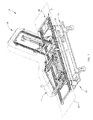
- Fig. 1 is a perspective view of a person support system with a person support surface according to one illustrative embodiment supported on a person support apparatus;
- Fig. 2 is a cross-sectional view of the person support surface and deck of Fig. 1 showing the cover and the mattress core in a reclined configuration;
- Fig. 3 is a cross-sectional side view of a portion of the person support surface of Fig. 1 showing the top ticking, fire barrier, and bottom ticking of the cover, and the mattress core;
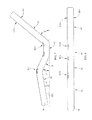
- Fig. 4 is a side view of the cover of Fig. 2 according to one illustrative embodiment, showing the sides of various sections having at least one diagonal end;
- Fig. 5 is a side view of the cover of Fig. 4 showing the various sections of the sides coupled together such that they are in the reclined configuration;
- Fig. 6 is a side view of the cover of Fig. 4 showing the various sections of the sides coupled together and in a substantially planar configuration with the excess material collected proximate to the bend points;
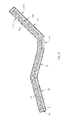
- Fig. 7 is a side view of the mattress core of Fig. 2 according to one illustrative embodiment in the reclined configuration with a plurality of relief cuts therein;
- Fig. 8 is a side view of the core of Fig. 7 showing the core in a substantially planar configuration
- Fig. 9 is a cross-sectional side view of the person support surface of Fig. 1 according to another illustrative embodiment showing a mattress core including a frame and a plurality of bladders;
- Fig. 10 is a cross-sectional side view of the person support surface of Fig. 1 according to another illustrative in the reclined configuration and including a plurality of oval bladders at a first pressure positioned proximate to the bend points; and
- Fig. 11 is a cross-sectional side view of the person support surface of Fig. 10 in the substantially planar configuration with the plurality of oval bladders at a second pressure and excess material collected proximate to the bend points.
- the person support system 10 includes a person support apparatus 12 and a person support surface 14 or mattress 14 supported on the person support apparatus 12.
- the person support apparatus 12 is a hospital bed frame and the mattress 14 is supported thereon.
- the person support apparatus 12 can also be a stretcher, an operating room table, a wheel chair, or other person supporting structure.
- the person support apparatus 12 includes a lower frame 16, supports 18 or lift mechanisms 18 coupled to the lower frame 16, and an upper frame 20 movably supported above the lower frame 16 by the supports 18 as shown in Fig. 1 .
- the lift mechanisms 18 are configured to raise and lower the upper frame 20 with respect to the lower frame 16 and move the upper frame 20 between various orientations, such as, Trendellenburg and reverse Trendellenburg.
- the upper frame 20 includes an upper frame base 24, a deck 26 coupled to the upper frame base 24, and a plurality of actuators 27 coupled to the upper frame base 24 and the deck 26 as shown in Fig. 1 .
- the plurality of actuators 27 are configured to move at least a portion of the deck 26 between various articulated configurations with respect to the upper frame base 24.
- the deck 26 includes a calf section 28, a thigh section 30, a seat section 32, and a head and torso section 34 as shown in Fig. 2 .
- the calf section 28 and the thigh section 30 define a lower limb support section LL1.
- the head and torso section 34 define an upper body support section U1.
- the seat section 32 defines the seat section S1.
- the calf section 28, the thigh section 30, and the seat section 32 define a lower body support section LB1. At least the calf section 28, the thigh section 30, and the head and torso section 34 are movable with respect to one another and/or the upper frame base 24. In one illustrative embodiment, the calf section 28, the thigh section 30, the seat section 32, and the head and torso section 34 cooperate to move the person support apparatus 12 between an substantially planar or lying down configuration and a chair configuration. In another illustrative embodiment, the calf section 28, the thigh section 30, the seat section 32, and the head and torso section 34 cooperate to move the person support apparatus 12 between a substantially planar or lying down configuration and an angled or reclined configuration. In yet another illustrative embodiment, the head and torso section 34 is moved such that it is at an angle of at least about 30° with respect to a reference plane RP1 passing through the upper frame 20.
- the person support surface 14 is configured to support a person thereon and move with the deck 20 between the various configurations.
- the person support surface 14 includes a calf portion 36, a thigh portion 38, a seat portion 40, and a head and torso portion 42 as shown in Figs. 2-10 , which are supported on corresponding sections of the deck 26.
- the person support surface 14 is a non-powered (static) surface as shown in Figs. 2 and 7-9 .
- the person support surface 14 is a powered (dynamic) surface as shown in Fig. 9-11 , which is configured to receive an input, such as, fluid from a fluid supply (not shown), that can change a characteristic of the surface.
- the person support surface 14 includes a mattress cover 44 and a mattress core 46 as shown in Figs. 2 and 3 .
- the person support surface 14 includes a temperature and moisture regulating topper (not shown) coupled to the mattress cover 44.
- the mattress cover 44 encloses the mattress core 46 and includes a fire barrier 48, a bottom ticking 50 or durable layer 50, and a top ticking 52.
- the fire barrier 48 is the innermost layer of the cover 44
- the top ticking 52 is the outermost layer
- the bottom ticking 50 is positioned between the fire barrier 48 and the top ticking 52 and is not coupled to the top ticking 52.
- the bottom ticking 50 and the top ticking 52 are vapor and air impermeable.
- the top ticking 52 and the bottom ticking 50 are composed of polyurethane coated nylon and the bottom ticking 50 is configured to facilitate movement of the top ticking 52 with respect to the fire barrier 48.
- the top ticking 52 and/or the bottom ticking 50 can be air and/or moisture permeable.
- the mattress core 46 can be composed of a single type of material or a combination of materials and/or devices.
- the mattress core 46 includes at least one fluid bladder 54 therein that receives fluid from a fluid supply (not shown) to maintain the fluid pressure within the fluid bladder 54 at a predetermined level.
- the powered surface can include non-powered components, such as, foam as shown in Fig. 9 .
- the mattress core 46 is composed of a cellular engineered material, such as, single density foam.
- the mattress core 46 includes at least one bladder 54, such as, a static air bladder or a static air bladder with foam contained therewithin, a metal spring and/or other non-powered support elements or combinations thereof.
- the mattress core 46 and includes multiple zones with different support characteristics configured to enhance pressure redistribution as a function of the proportional differences of a person's body.
- the mattress core 46 includes various layers and/or sections of foam having different impression load deflection (ILD) characteristics, such as, in the NP100 Prevention Surface, AccuMax QuantumTM VPC Therapy Surface, and NP200 Wound Surfaces sold by Hill-Rom®.
- ILD impression load deflection
- the mattress cover 44 and/or the mattress core 46 can be configured in a number of ways to maximize pressure relief when the various portions, such as, the calf portion 36, thigh portion 38, and head and torso portion 42, are at an angle with respect to the reference plane RP1.
- One way to maximize pressure relief is to design the mattress 14 such that the mattress 14 is in a neutral or rest state in the angled configuration.
- the mattress 14 is in a neutral or rest state when the tension and compression in the various sections and/or intersections of the various sections is minimized.
- the mattress 14 is in a neutral or rest state when there is substantially no tension or compression at the intersections of the various sections.
- Mattresses are generally designed to maximize pressure relief when the mattress is in the substantially planar configuration.
- the various portions of upwardly facing surface UF1 which are configured to interface with an occupant, are substantially the same length as the corresponding portions of the downwardly facing surface DF1, which is configured to contact the corresponding portions of a deck.
- the upwardly facing surfaces UF1 and the downwardly facing surfaces DF1 of various sections are a different length.
- the length of the upwardly facing surface UF1 of the head and torso portion 42 is a first length L1 and the downwardly facing surface DF1 of the head and torso portion 42 (from the intersection of the seat portion 36 and the head and torso portion 42 to the end of the head and torso portion 42) is a second length L2, which is longer than the first length L1.
- the upwardly facing surface UF1 of the calf portion 36 is a first length L1 and the downwardly facing surface DF1 of the calf portion 36 (from the intersection of the calf portion 36 and the thigh portion 38 to the end of the calf portion 36) is a second length L2, which is shorter than the first length L1.
- the cover 44 can be configured a number of ways to account for the different lengths.
- at least one portion of the cover 44 such as, the intersection of the seat section 40 and the head and torso section 42, includes material that is configured to expand/contract to account for the different lengths of material required to cover the upper body support section U1 and lower body support sections LB1.
- the portions of the cover 44 such as, the calf portion 36, the thigh portion 38, the seat portion 40, and the head and torso portion 42, are sized independent of one another such that each portion of the upwardly facing surface UF1 and the corresponding downwardly facing surface DF1 has a different length.
- the portions can be connected together via an elastic material that stretches to account for the different lengths of material.
- the excess material of the cover 44 can be collected, for example, by pleating, gathering, or folding, at the bend points BP1 of the mattress 14, i.e., where the portions are connected to one another, to account for the different lengths of material.
- an elastic strap (not shown) is used to collect the excess material.
- excess material on the downwardly facing surface DF1 at about the intersection of the head and torso support portion 42 (or the material on the upwardly facing surface UF1 at about the intersection of the calf portion 36 and the thigh portion 38) can be configured to collect when the mattress 14 is in the substantially planar configuration and expand when the mattress 14 moves from the substantially planar configuration to the angled configuration.
- excess material is collected in areas where the interface pressure is comparatively lower, such as, behind the occupant's knee.
- the sides of the mattress 14 can be formed such that when they are coupled, i.e., via welding or stitching, to one another they mimic the profile of the mattress 14 when it is in the angled configuration as shown in Figs. 4-6 .
- the calf portion 36 and head and torso portion 42 are formed with one angled or diagonal end and the thigh portion 38 and seat portion 40 are formed with both ends angled as shown in Fig. 4 .
- the sides of the mattress 14 are formed as part of the upwardly facing surface UF1 or downwardly facing surface DF1.
- the mattress core 46 can be configured in a number of ways maximize pressure relief when the various portions, such as, the calf portion 36, thigh portion 38, and head and torso portion 42, are at an angle with respect to the reference plane RP1.
- the mattress core 46 is composed of foam that is molded such that the head and torso section 42 of the mattress core 46 is at an angle ⁇ with respect to a reference plane RP1, and the calf portion 36 and the thigh portion 38 are at an angle ⁇ and ⁇ , respectively, with respect to the reference plane RP1 when the mattress 14 is in the neutral state.
- angle ⁇ is between about 25° and about 45° with respect to the reference plane RP1
- angle ⁇ and ⁇ are between about 10° and 20° with respect to the reference plane RP1.
- the mattress core 46 is molded such that the magnitude of angles ⁇ , ⁇ and ⁇ are greater than 0° with respect to the reference plane RP1.
- the molded mattress core 46 includes relief cuts RC1 that assist the portions of the mattress 14 in moving from the angled configuration to the substantially planar configuration.
- the relief cuts RC1 are located on only one of the upwardly facing surface UF1 and the downwardly facing surface DF1 of the mattress core 46 and are configured to expand/compress as the mattress 14 is moved from the angled configuration to the substantially planar configuration. In some contemplated embodiments, the relief cuts RC1 are located on both the upwardly facing surface UF1 and the downwardly facing surface DF1. In some contemplated embodiments, the mattress core 46 can be pulled or pushed to move between the angled configuration and the substantially planar configuration.
- the mattress core 46 includes a frame FR1 and a plurality of bladders BL1.
- the frame FR1 is composed of foam having a relatively high ILD, such as, for example, a rating of about 61.
- the frame FR1 is configured such that the various portions of the frame FR1, the calf portion 36, the thigh portion 38, the seat portion 40, and the head and torso portion 42, are joined together at the bend points BP1 of the person support surface 14 such that the mattress core 46 is in the angled configuration in the neutral or rest state.
- the frame FR1 provides support and helps maintain the shape of the mattress 14.
- the frame FR1 helps maintain the various portions of the mattress 14 at angles ⁇ , ⁇ and ⁇ with respect to the reference plane RP1.
- the frame FR1 includes a recessed portion that the bladders BL1 are positioned in.
- the bladders BL1 are static air bladders that are in fluid communication with one another so that the air in the bladders BL1 can be redistributed when an occupant is supported on the mattress 14 to substantially equalize the air pressure across the array of bladders BL1.
- the bladders BL1 can be configured to receive fluid from a fluid supply (not shown).
- the mattress core 46 includes a plurality of generally tubular fluid bladders 54, some of which have a substantially round cross-section 54a and some of which have a wedge shaped cross-section 54b.
- the fluid bladders 55b are oval or egg-shaped.
- the fluid bladders 54 can have at least one smaller bladder (not shown) positioned on a larger bladder (not shown) to form a wedge-like profile.
- the mattress core 46 also includes a semi-rigid frame, such as, the frame FR1, that supports the fluid bladders 54a and 54b.
- both types of fluid bladder 54a and 54b are fully inflated to a predetermined pressure, the head and torso portion 42 is at an angle with respect to the seat portion 40 and the person support surface is in the neutral or rest state.
- the fluid bladders 54b are deflated to a second predetermined pressure, the head and torso portion 42 is substantially co-planar with the seat section 40 and the person support surface 14 is in the substantially planar configuration.
- Fluid bladders 54b are positioned proximate to the bend points BP1 of the mattress 14 where the various sections intersect one another, such as, where the head and torso support portion 42 intersects the seat portion 40.
- the smaller diameter bladder (not shown) is positioned proximate to the inside of the bend point BP1 and the larger diameter bladder (not shown) is positioned proximate to the outside of the bend.
- a person support surface including a first support section and a second support section comprises a first surface and a second surface spaced apart from the first surface.
- the first support section of the first surface is a first length and the first support section of the second surface is a second length.
- the second length is greater than the first length.
- a person support comprises a core including a first support section and a second support section.
- the core is shaped such that the first support section is at an angle with respect the second support section in a neutral state.
- the first support section is configured to move from the neutral state to a second position where the first support section is substantially co-planar with the second support section.
- a person support surface including a first support section and a second support section comprises a cover defining an inner chamber and a core positionable within the inner chamber.
- the core is formed such that the first support section is initially at an angle with respect the second support section in a first position.
- the first support section is configured to move from the first position to a second position where the first support section and the second support section are substantially co-planar.
- the interface between the first support section and the second support section is in a neutral state in the first position and in compression in the second position.
- a person support surface comprises a first support section and a second support section.
- the first support section and the second support section are formed such that the first support section is at an angle with respect the second support section in a first position and is configured to move from the first position to a second position where the first support section and the second support section are substantially co-planar.
- the interface between the first support section and the second support section is in a neutral state in the first position and in compression in the second position.
- a person support surface comprises a first support section and a second support section.
- the first support section is at an angle with respect the second support section in a neutral state.
- the first support section is configured to move from the neutral state to a second position where the first support section is substantially co-planar with the second support section.
- a person support surface including a first support section and a second support section comprises a first surface and a second surface spaced apart from the first surface.
- the first support section of the first surface is a first length and the first support section of the second surface is a second length.
- the second length is greater than the first length.
- the first support section is movable from a first position where the first support section is at an angle with respect to the second support section and is in a neutral state to a second position where the first support section is substantially co-planar with the second support section.
Landscapes
- Health & Medical Sciences (AREA)
- Nursing (AREA)
- Life Sciences & Earth Sciences (AREA)
- Animal Behavior & Ethology (AREA)
- General Health & Medical Sciences (AREA)
- Public Health (AREA)
- Veterinary Medicine (AREA)
- Invalid Beds And Related Equipment (AREA)
- Orthopedics, Nursing, And Contraception (AREA)
- Professional, Industrial, Or Sporting Protective Garments (AREA)
Applications Claiming Priority (1)
| Application Number | Priority Date | Filing Date | Title |
|---|---|---|---|
| US13/249,689 US20130081205A1 (en) | 2011-09-30 | 2011-09-30 | Person support surface |
Publications (2)
| Publication Number | Publication Date |
|---|---|
| EP2574322A2 true EP2574322A2 (de) | 2013-04-03 |
| EP2574322A3 EP2574322A3 (de) | 2014-06-25 |
Family
ID=46939650
Family Applications (1)
| Application Number | Title | Priority Date | Filing Date |
|---|---|---|---|
| EP12186258.5A Withdrawn EP2574322A3 (de) | 2011-09-30 | 2012-09-27 | Personenliegenoberfläche |
Country Status (3)
| Country | Link |
|---|---|
| US (2) | US20130081205A1 (de) |
| EP (1) | EP2574322A3 (de) |
| JP (1) | JP6166520B2 (de) |
Cited By (3)
| Publication number | Priority date | Publication date | Assignee | Title |
|---|---|---|---|---|
| EP2863858A4 (de) * | 2012-06-21 | 2015-10-07 | Hill Rom Services Inc | Patiententragesysteme und verfahren zur verwendung |
| US10391008B2 (en) | 2012-06-21 | 2019-08-27 | Hill-Rom Services, Inc. | Patient support system and methods of use |
| US10806655B2 (en) | 2012-06-21 | 2020-10-20 | Hill-Rom Services, Inc. | Mattress bladder control during patient bed egress |
Families Citing this family (10)
| Publication number | Priority date | Publication date | Assignee | Title |
|---|---|---|---|---|
| US8856993B2 (en) * | 2008-04-15 | 2014-10-14 | Hill-Rom Services, Inc. | Temperature and moisture regulating topper for non-powered person-support surfaces |
| US20150107023A1 (en) * | 2013-10-18 | 2015-04-23 | Chi-Tzung Huang | Electric bed structure |
| US20150208813A1 (en) * | 2014-01-24 | 2015-07-30 | L & P Property Management Company | Mattress-retention decking |
| US9808093B2 (en) * | 2015-03-10 | 2017-11-07 | Ascion, Llc | Adjustable bed apparatus and methods incorporating lumbar and neck supports |
| US11304864B2 (en) * | 2016-09-02 | 2022-04-19 | Stryker Corporation | Patient support systems with a chair configuration and a stowable foot section |
| DK179748B1 (en) * | 2017-09-15 | 2019-05-01 | Bergmann Jean-Paul | Hospital bed with an enclosed housing, easy to clean and maintain |
| JP6687769B1 (ja) * | 2019-01-15 | 2020-04-28 | パラマウントベッド株式会社 | エアマットレス |
| JP7042863B2 (ja) * | 2020-04-02 | 2022-03-28 | パラマウントベッド株式会社 | エアマットレス |
| US20210307523A1 (en) * | 2020-04-07 | 2021-10-07 | Lg Electronics Inc. | Bed |
| EP4633571A1 (de) | 2022-12-13 | 2025-10-22 | Afifi, Ahmed M. | Chirurgische stützsysteme, vorrichtungen und verfahren |
Family Cites Families (16)
| Publication number | Priority date | Publication date | Assignee | Title |
|---|---|---|---|---|
| US3188142A (en) * | 1962-07-30 | 1965-06-08 | Jack P Probst | Seat construction |
| US5051673A (en) * | 1985-12-30 | 1991-09-24 | Goodwin Vernon L | Patient support structure |
| US5090695A (en) * | 1989-05-31 | 1992-02-25 | Ciolino Peter A | Exercise float and method of use |
| US5214809A (en) * | 1992-06-29 | 1993-06-01 | Paul Stuart | Articulated mattress for adjustable bed |
| AU1118799A (en) * | 1997-10-24 | 1999-05-17 | Hill-Rom, Inc. | Mattress having air fluidized sections |
| JP3634170B2 (ja) * | 1998-10-19 | 2005-03-30 | フランスベッド株式会社 | エアーマットレス装置 |
| JP4546613B2 (ja) * | 2000-05-26 | 2010-09-15 | オカモト株式会社 | 床擦れ防止マット |
| JP2002065406A (ja) * | 2000-09-04 | 2002-03-05 | Molten Corp | エアマット |
| US6694549B2 (en) * | 2001-04-20 | 2004-02-24 | Hill-Rom Services, Inc. | Bed frame with reduced-shear pivot |
| EP1572059B1 (de) * | 2002-03-18 | 2010-09-29 | Hill-Rom Services, Inc. | Krankenbett mit einer geregelten aufblasbaren auflage |
| US6721978B1 (en) * | 2003-01-14 | 2004-04-20 | Harry Tankersley | Head bed |
| US6895614B1 (en) * | 2003-02-10 | 2005-05-24 | Shawn Peck | Hunting mat |
| GB0514927D0 (en) * | 2005-07-20 | 2005-08-24 | Huntleigh Technology Plc | Mattress |
| US9320663B2 (en) * | 2008-06-27 | 2016-04-26 | Kreg Medical, Inc. | Bed gap filler |
| FR2949321B1 (fr) * | 2009-08-31 | 2011-09-16 | Hill Rom Ind Sa | Dispositif de support comprenant un matelas de dimensions ajustables a l'aide de cellules gonflables |
| US10238566B2 (en) * | 2010-12-08 | 2019-03-26 | Hill-Rom Services, Inc. | Mattress bladder boosting during chair egress |
-
2011
- 2011-09-30 US US13/249,689 patent/US20130081205A1/en not_active Abandoned
-
2012
- 2012-09-27 EP EP12186258.5A patent/EP2574322A3/de not_active Withdrawn
- 2012-09-27 JP JP2012214185A patent/JP6166520B2/ja not_active Expired - Fee Related
-
2014
- 2014-01-21 US US14/159,697 patent/US20140130257A1/en not_active Abandoned
Non-Patent Citations (1)
| Title |
|---|
| None |
Cited By (6)
| Publication number | Priority date | Publication date | Assignee | Title |
|---|---|---|---|---|
| EP2863858A4 (de) * | 2012-06-21 | 2015-10-07 | Hill Rom Services Inc | Patiententragesysteme und verfahren zur verwendung |
| US10391008B2 (en) | 2012-06-21 | 2019-08-27 | Hill-Rom Services, Inc. | Patient support system and methods of use |
| US10555850B2 (en) | 2012-06-21 | 2020-02-11 | Hill-Rom Services, Inc. | Patient support systems and methods of use |
| US10806655B2 (en) | 2012-06-21 | 2020-10-20 | Hill-Rom Services, Inc. | Mattress bladder control during patient bed egress |
| US11116681B2 (en) | 2012-06-21 | 2021-09-14 | Hill-Rom Services, Inc. | Patient support systems and methods of use |
| US12102577B2 (en) | 2012-06-21 | 2024-10-01 | Hill-Rom Services, Inc. | Mattress bladder control using a bleed valve |
Also Published As
| Publication number | Publication date |
|---|---|
| EP2574322A3 (de) | 2014-06-25 |
| JP6166520B2 (ja) | 2017-07-19 |
| US20140130257A1 (en) | 2014-05-15 |
| JP2013078577A (ja) | 2013-05-02 |
| US20130081205A1 (en) | 2013-04-04 |
Similar Documents
| Publication | Publication Date | Title |
|---|---|---|
| EP2574322A2 (de) | Personenliegenoberfläche | |
| US10517407B2 (en) | Adjustable comfort mattress system and processes | |
| EP1021154B1 (de) | Krankenhausbett mit zurückziehbarem fussteil | |
| US9750655B2 (en) | Conformable support system | |
| EP1021108B1 (de) | Matratzenstruktur | |
| US20050028289A1 (en) | Mattress | |
| US20110173758A1 (en) | Inflatable mattress and method of operating same | |
| JP2017508547A (ja) | 硬さが調節可能なベッド等のマットレス構造 | |
| JP7130000B2 (ja) | 調整可能な硬さを有するベッドなどのマットレス構成 | |
| US20150282630A1 (en) | Mattress lift system | |
| US6311351B1 (en) | Pressure reducing mattress with localized pressure point relief | |
| AU2017264407B2 (en) | Adjustable width user support | |
| JP6678947B2 (ja) | エアマットレス及びエアセル | |
| EP2042058B1 (de) | Kraftaufnahmevorrichtung für Bett | |
| JP2008289630A (ja) | 床擦れ防止ベッド | |
| WO2009042647A2 (en) | Bolster system for low air loss mattress | |
| KR20260030524A (ko) | 접이식 매트리스 및 이를 포함하는 각도조절 침대 | |
| CA2520743C (en) | Hospital bed having an adjustable length deck | |
| AU2023201714A1 (en) | A healthcare support surface | |
| KR20250175786A (ko) | 의료용 매트리스 장치 | |
| WO1998041127A1 (en) | Improved coil spring unit and base support | |
| CA2306057A1 (en) | Improved coil spring unit and base support |
Legal Events
| Date | Code | Title | Description |
|---|---|---|---|
| PUAI | Public reference made under article 153(3) epc to a published international application that has entered the european phase |
Free format text: ORIGINAL CODE: 0009012 |
|
| AK | Designated contracting states |
Kind code of ref document: A2 Designated state(s): AL AT BE BG CH CY CZ DE DK EE ES FI FR GB GR HR HU IE IS IT LI LT LU LV MC MK MT NL NO PL PT RO RS SE SI SK SM TR |
|
| AX | Request for extension of the european patent |
Extension state: BA ME |
|
| PUAL | Search report despatched |
Free format text: ORIGINAL CODE: 0009013 |
|
| AK | Designated contracting states |
Kind code of ref document: A3 Designated state(s): AL AT BE BG CH CY CZ DE DK EE ES FI FR GB GR HR HU IE IS IT LI LT LU LV MC MK MT NL NO PL PT RO RS SE SI SK SM TR |
|
| AX | Request for extension of the european patent |
Extension state: BA ME |
|
| RIC1 | Information provided on ipc code assigned before grant |
Ipc: A61G 7/015 20060101AFI20140516BHEP Ipc: A61G 13/08 20060101ALI20140516BHEP Ipc: A47C 27/18 20060101ALN20140516BHEP Ipc: A47C 27/08 20060101ALN20140516BHEP |
|
| STAA | Information on the status of an ep patent application or granted ep patent |
Free format text: STATUS: THE APPLICATION IS DEEMED TO BE WITHDRAWN |
|
| 18D | Application deemed to be withdrawn |
Effective date: 20150106 |