EP2574325A2 - Ensemble chirurgical - Google Patents
Ensemble chirurgical Download PDFInfo
- Publication number
- EP2574325A2 EP2574325A2 EP12186260A EP12186260A EP2574325A2 EP 2574325 A2 EP2574325 A2 EP 2574325A2 EP 12186260 A EP12186260 A EP 12186260A EP 12186260 A EP12186260 A EP 12186260A EP 2574325 A2 EP2574325 A2 EP 2574325A2
- Authority
- EP
- European Patent Office
- Prior art keywords
- post
- sleeve
- assembly
- throat
- opening
- Prior art date
- Legal status (The legal status is an assumption and is not a legal conclusion. Google has not performed a legal analysis and makes no representation as to the accuracy of the status listed.)
- Granted
Links
Images




Classifications
-
- A—HUMAN NECESSITIES
- A61—MEDICAL OR VETERINARY SCIENCE; HYGIENE
- A61G—TRANSPORT, PERSONAL CONVEYANCES, OR ACCOMMODATION SPECIALLY ADAPTED FOR PATIENTS OR DISABLED PERSONS; OPERATING TABLES OR CHAIRS; CHAIRS FOR DENTISTRY; FUNERAL DEVICES
- A61G13/00—Operating tables; Auxiliary appliances therefor
- A61G13/0036—Orthopaedic operating tables
-
- A—HUMAN NECESSITIES
- A61—MEDICAL OR VETERINARY SCIENCE; HYGIENE
- A61F—FILTERS IMPLANTABLE INTO BLOOD VESSELS; PROSTHESES; DEVICES PROVIDING PATENCY TO, OR PREVENTING COLLAPSING OF, TUBULAR STRUCTURES OF THE BODY, e.g. STENTS; ORTHOPAEDIC, NURSING OR CONTRACEPTIVE DEVICES; FOMENTATION; TREATMENT OR PROTECTION OF EYES OR EARS; BANDAGES, DRESSINGS OR ABSORBENT PADS; FIRST-AID KITS
- A61F5/00—Orthopaedic methods or devices for non-surgical treatment of bones or joints; Nursing devices ; Anti-rape devices
- A61F5/01—Orthopaedic devices, e.g. long-term immobilising or pressure directing devices for treating broken or deformed bones such as splints, casts or braces
- A61F5/04—Devices for stretching or reducing fractured limbs; Devices for distractions; Splints
-
- A—HUMAN NECESSITIES
- A61—MEDICAL OR VETERINARY SCIENCE; HYGIENE
- A61G—TRANSPORT, PERSONAL CONVEYANCES, OR ACCOMMODATION SPECIALLY ADAPTED FOR PATIENTS OR DISABLED PERSONS; OPERATING TABLES OR CHAIRS; CHAIRS FOR DENTISTRY; FUNERAL DEVICES
- A61G13/00—Operating tables; Auxiliary appliances therefor
- A61G13/0036—Orthopaedic operating tables
- A61G13/0081—Orthopaedic operating tables specially adapted for hip surgeries
-
- A—HUMAN NECESSITIES
- A61—MEDICAL OR VETERINARY SCIENCE; HYGIENE
- A61G—TRANSPORT, PERSONAL CONVEYANCES, OR ACCOMMODATION SPECIALLY ADAPTED FOR PATIENTS OR DISABLED PERSONS; OPERATING TABLES OR CHAIRS; CHAIRS FOR DENTISTRY; FUNERAL DEVICES
- A61G13/00—Operating tables; Auxiliary appliances therefor
- A61G13/10—Parts, details or accessories
- A61G13/12—Rests specially adapted therefor; Arrangements of patient-supporting surfaces
- A61G13/1205—Rests specially adapted therefor; Arrangements of patient-supporting surfaces for specific parts of the body
- A61G13/123—Lower body, e.g. pelvis, hip, buttocks
-
- A—HUMAN NECESSITIES
- A61—MEDICAL OR VETERINARY SCIENCE; HYGIENE
- A61G—TRANSPORT, PERSONAL CONVEYANCES, OR ACCOMMODATION SPECIALLY ADAPTED FOR PATIENTS OR DISABLED PERSONS; OPERATING TABLES OR CHAIRS; CHAIRS FOR DENTISTRY; FUNERAL DEVICES
- A61G13/00—Operating tables; Auxiliary appliances therefor
- A61G13/10—Parts, details or accessories
- A61G13/12—Rests specially adapted therefor; Arrangements of patient-supporting surfaces
- A61G13/128—Rests specially adapted therefor; Arrangements of patient-supporting surfaces with mechanical surface adaptations
- A61G13/1285—Rests specially adapted therefor; Arrangements of patient-supporting surfaces with mechanical surface adaptations having modular surface parts, e.g. being replaceable or turnable
Definitions
- the subject matter described herein relates to a surgical assembly and particularly to a quick release surgical post and related structural elements.
- One example application for the assembly is as a perineal post for applying countertraction during procedures such as fracture repair, hip arthroscopy and hip replacement surgery.
- One embodiment of a surgical assembly as described herein comprises a post having a longitudinally extending axis, a support for resisting movement of the post in a negative longitudinal direction, and a platform offset from the support in a positive longitudinal direction.
- the platform includes an opening through which the post projects.
- the opening includes a throat.
- the post has a first dimension which renders the post incapable of passing through the throat and a second dimension which renders the post capable of passing through the throat.
- FIG. 1 shows a generically depicted perineal post assembly in the context of a supine patient P lying on an operating table T.
- the assembly includes a perineal post 200 extending vertically from the table, and a pad 210 mounted on the post.
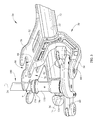
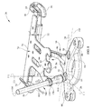
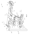
- FIGS. 2-5 show a surgical assembly, specifically a countertraction assembly 20, and three mutually orthogonal reference axes: a longitudinal axis 22, a lateral axis 24, and a transverse axis 26.
- the axes illustrated in the drawings each extend in respective positive directions from origin O. Left and right lateral directions are indicated by directional arrows L and R and correspond to the positive and negative lateral directions respectively.
- Countertraction assembly 20 includes a laterally extending beam 32, left and right attachment brackets 34, and left and right handles 36.
- a surgical table extender includes rail adaptors 40, only the left one of which is shown, to permit equipment and accessories to be attached to rails extending along the sides of the table.
- a hook 42 is removably attached to each rail adaptor with a threaded connector having a knob 44 and a threaded shank (not visible).
- Each bracket 34 engages a hook 42 to cantilever mount the countertraction assembly on the surgical table.
- An assembly substructure includes a truss 50 connected to the beam.
- the truss has an upper leg 52 and a lower leg 54.
- the substructure also includes a support or yoke 56 connected to the lower leg and having left and right feet 60.
- a locator 62 which is at least partly frustoconical, projects from each foot in the positive longitudinal direction.
- the countertaction assembly also includes a platform 70 offset from support 56 in the positive longitudinal direction and secured by screws 72 to beam 32 and to upper leg 52 of truss 50.
- the platform has a substantially planar upper surface 74, a substantially planar lower surface 76, and a thickness t.
- the planes of the upper and lower surfaces define an interplanar envelope 80 also having a thickness t.
- the platform includes left and right platform openings 82 each have a circular portion 84 with a first diameter D1 and a throat portion 86 extending from the circular portion to an edge 88 of the platform.
- the throat has a minimum lateral width W in the interplanar envelope such that W is smaller than D1.
- the countertraction assembly also includes a post 100 comprising a pole 102 having an axis 104 (seen best in FIGS. 5 and 6 ) and a pair of diametrically opposed slots 106 (visible in FIG. 5 ).
- the pole has a circular cross section whose diameter is, at most, no greater than throat width W and, in practice, is small enough to pass through the throat in the transverse direction.
- the post also includes a retainer illustrated as a sleeve 110 that circumscribes the pole.
- a sleeve dowel 112 extends through holes 114 in the sleeve and through slots 106 in the pole. Dowel 112 is retained in holes 114 by friction fit and/or an adhesive.
- the presence of slots 106 enables the sleeve to translate longitudinally along the pole.
- the sleeve has a relatively large diameter portion that defines a shoulder 120 and that cooperates with pole 102 to define an annulus 122.
- the illustrated post also includes a mount adaptor 130 secured to the pole by an adaptor dowel 132 that extends through holes 134 in the adaptor and corresponding holes 136 in the pole. Dowel 132 is retained in holes 134, 136 by friction fit and/or an adhesive. A ledge 138 on the adaptor defines the lower end of annulus 122. As seen best in FIG. 5 the locator is received by the post, specifically by the mount adaptor in the illustrated embodiment, to locate or position the post spatially and to provide some resistance to movement of the post in the lateral and transverse directions. The support resists movement of the post in the negative longitudinal direction.
- a coil spring 150 resides in annulus 122 radially intermediate the sleeve and the pole.
- the spring extends longitudinally from adaptor ledge 138 to shoulder 120.
- FIG. 2 shows post 100 positioned on locator 62 with the pole projecting through circular portion 84 of opening 82.
- spring 150 is compressed and therefore biases the sleeve longitudinally to a first position in which a first portion 154 of the sleeve having a diameter larger than width W of the throat projects into interplanar envelope 80 within the circular portion 84 of opening 82, and in which a second, lip portion 156 of the sleeve contacts and bears against lower surface 76 of the platform.
- the post has a first dimension in the interplanar envelope large enough in relation to throat width W to render the post incapable of passing through the throat.
- the first dimension is the diameter of the sleeve first portion 154.
- the first position is a default position.
- the assembly as seen in FIG. 2 is in a secured or locked state, i.e. the locator is received in the post and the sleeve is snugly confined by circular portion 84 of opening 82 such that the post cannot be easily moved out of position. In this state the assembly can be used to apply countertraction to a patient during surgery.
- FIGS. 3-4 show sleeve 110 having been translated to a second position by the application of a force F to further compress spring 150 thereby counteracting the biasing force that would otherwise urge the sleeve to the first position.
- the force is applied by an attendant who grasps the sleeve and pushes it in the negative longitudinal direction.
- no portion of the sleeve having a diameter larger than width W of the throat projects into interplanar envelope 80.
- the attendant would typically push the sleeve far enough that no portion of the sleeve projected into the interplanar envelope.
- the post has a second dimension in the interplanar envelope small enough in relation to throat width W to render the post capable of passing through the throat.
- the second dimension is the diameter of pole 102. As will become clear after describing FIG. 6 , the second dimension of the illustrated embodiment would extend slightly above the plane of platform upper surface 74. The assembly as seen in FIGS. 3-4 is in a non-secured or unlocked state.
- FIG. 5 shows the sleeve in a relaxed state, as it would be if the post were in place on the adaptor as in FIG. 2 but the platform were not present.
- FIG. 6 shows the post having been rotated about a laterally extending axis 160 to effect its removal.
- Clearance gap G FIG. 5
- Locator geometries other than frustoconical can also be used provided only that the locator geometry will properly locate the post and will allow it to be rotated into position for installation and out of position for removal.
- the portion of the post that passes through the throat includes a small segment of the post that, in the position of FIG. 2 , is slightly above the plane of platform upper surface 74.
- the second dimension of the illustrated embodiment would extend slightly above the plane of platform upper surface 74.
- the post can be engaged with and disengaged from the support and platform without any purposeful translation of the post longitudinally or in the direction of axis 104.
- a user might effect some incidental movement of the post longitudinally or in the direction of axis 104, such motion is not necessary to engage the post with the support and platform or to disengage it from the support and platform.
- FIG. 7 shows sleeve 110 and mount adaptor 130 as previously described and also shows a prototype sleeve 110' and adaptor 130'.
- the prototype sleeve is believed to be less ergonomic than sleeve 110 but is otherwise functionally and conceptually equivalent to sleeve 110.
- FIG. 8 is a view showing a variant of the countertraction assembly.
- each foot includes a counterbore 64 with a chamfer 66 in lieu of locator 62 seen in other embodiments.
- the diameter of the nonchamfered portion of the counterbore is slightly oversized relative to the diameter of the bottom of the post, for example by about 0.020 inches (approximately 0.5 mm).
- the post fits snugly into the counterbore, but, due to chamfer 66 and the slight oversizing of the counterbore, can nevertheless be rotated about a laterally extending axis 160 to effect installation or removal.
- engagement of the post with the platform and support and disengagement of the post from the platform and support is carried out without the need for any purposeful translation of the post longitudinally or in the direction of axis 104. If the fit between the counterbore and post were too tight to permit rotation about axis 160, some small amount of purposeful translation of the post in the longitudinal direction (and in the direction of axis 104) would be necessary. However the required translation would be limited to the amount necessary for the bottom of the post to clear the top of the counterbore. It would not be necessary to translate the post in the longitudinal direction by an amount sufficient to cause the lower end of the post to pass longitudinally through platform opening 82.
- FIG. 9 is a view showing another variant of the countertraction assembly.
- the post has a circular cross section, and the sleeve 110 seen in other embodiments is absent.
- opening 82' has a semicircular portion 90, which conforms to the cross sectional geometry of the post, and a constant width portion 92 having a width W1. Width W1, the diameter of semicircular portion 90, and the diameter of post 102 are substantially equal to each other.
- Each foot 60 includes a recess 94 with a semicircular portion 96, which conforms to the cross sectional geometry of the post, and a constant width portion 98 having a width W2.
- a locking element 140 having first and second wings 142, 144 is pivot mounted alongside one or both edges of the constant width portions 92, 98 of opening 82' and recess 94 respectively.
- Each locking element is rotatable about an axis A.
- Each locking element is spring loaded in rotational direction S to the position shown in the illustration in which first wing 142 of each element projects into the planform of the opening or recess either within or outside of respective interplanar envelopes 80, 101.
- the deflection occurs without direct user intervention, i.e. without a user having to manipulate the elements independently of moving the post.
- the elements spring back to their undeflected position. Because locking elements 140 cannot rotate any further in direction S than the position shown in the illustration, the first wing 142 of each element resists unintentional removal or accidental dislodgement of the post.
- a user In order to remove the post a user directly manipulates the lock by squeezing second wings 144 toward each other thus rotating the locking elements in direction T until first wings 142 no longer impede movement of the post in the direction of transverse axis 26. While holding the locking elements in this position the user independently moves the post out of the opening and recess in the transverse direction.
- projection 62, counterbore 64, constant width recess 94 /locking element 140, constant width opening 82' /locking element 140 and non-constant width opening 82, used as appropriate at foot 60 and/or platform 70 may also provide satisfactory results. It is envisioned that projection 62, counterbore 64, and constant width recess 94 /locking element 140 are the features best suited for use on feet 60 of support 56 and that constant width opening 82' /locking element 140 and non-constant width opening 82 are the features best suited for use on the platform.
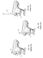
- FIGS. 10A-10C are a sequence of views showing a pre-existing countertraction assembly.
- the post 100' extends through a simple opening 82' in platform 70'.
- removal of the post involves a considerable movement of the post in the positive longitudinal direction which, as noted earlier in this application, can complicate intraoperative removal of the post.
Landscapes
- Health & Medical Sciences (AREA)
- General Health & Medical Sciences (AREA)
- Engineering & Computer Science (AREA)
- Biomedical Technology (AREA)
- Life Sciences & Earth Sciences (AREA)
- Animal Behavior & Ethology (AREA)
- Public Health (AREA)
- Veterinary Medicine (AREA)
- Orthopedic Medicine & Surgery (AREA)
- Nursing (AREA)
- Heart & Thoracic Surgery (AREA)
- Vascular Medicine (AREA)
- Surgical Instruments (AREA)
- Accommodation For Nursing Or Treatment Tables (AREA)
Applications Claiming Priority (1)
| Application Number | Priority Date | Filing Date | Title |
|---|---|---|---|
| US13/250,381 US8997749B2 (en) | 2011-09-30 | 2011-09-30 | Surgical assembly |
Publications (3)
| Publication Number | Publication Date |
|---|---|
| EP2574325A2 true EP2574325A2 (fr) | 2013-04-03 |
| EP2574325A3 EP2574325A3 (fr) | 2013-05-01 |
| EP2574325B1 EP2574325B1 (fr) | 2014-10-22 |
Family
ID=46963593
Family Applications (1)
| Application Number | Title | Priority Date | Filing Date |
|---|---|---|---|
| EP12186260.1A Active EP2574325B1 (fr) | 2011-09-30 | 2012-09-27 | Ensemble chirurgical |
Country Status (2)
| Country | Link |
|---|---|
| US (2) | US8997749B2 (fr) |
| EP (1) | EP2574325B1 (fr) |
Cited By (7)
| Publication number | Priority date | Publication date | Assignee | Title |
|---|---|---|---|---|
| USD878836S1 (en) | 2017-08-17 | 2020-03-24 | Stryker Corp. | Table extender |
| US10828218B2 (en) | 2015-06-05 | 2020-11-10 | Stryker Corporation | Surgical table and accessories to facilitate hip arthroscopy |
| CN113208846A (zh) * | 2021-03-04 | 2021-08-06 | 周瑞军 | 一种肛肠科术后换药趴伏姿态下隐私自动遮蔽方法 |
| US11510805B2 (en) | 2017-02-06 | 2022-11-29 | Stryker Corp. | Anatomical gripping system for gripping the leg and foot of a patient when effecting hip distraction and/or when effecting leg positioning |
| US11559455B2 (en) | 2017-02-06 | 2023-01-24 | Stryker Corp. | Distraction frame for effecting hip distraction |
| US11564855B2 (en) | 2020-09-28 | 2023-01-31 | Stryker Corporation | Systems and methods for supporting and stabilizing a patient during hip distraction |
| US11684532B2 (en) | 2017-02-06 | 2023-06-27 | Stryker Corp. | Method and apparatus for supporting and stabilizing a patient during hip distraction |
Families Citing this family (8)
| Publication number | Priority date | Publication date | Assignee | Title |
|---|---|---|---|---|
| US9161875B2 (en) | 2012-09-07 | 2015-10-20 | Allen Medical Systems, Inc. | Multi-axis joint for a spar of a limb holder |
| ITMI20121546A1 (it) * | 2012-09-18 | 2014-03-19 | Medacta Int Sa | Piano adattatore per tavolo chirurgico, in particolare per operazioni di sostituzione dell¿anca con approccio anteriore |
| US10022259B2 (en) * | 2013-04-24 | 2018-07-17 | Pivot Medical, Inc. | Apparatus and method for distracting the hip joint |
| EP2873405B1 (fr) * | 2013-11-18 | 2016-05-18 | Schaerer Medical Management AG | Table d'exploitation modulaire |
| ITUA20162775A1 (it) * | 2016-04-21 | 2017-10-21 | Medacta Int Sa | Piano adattatore per tavolo chirurgico e tavolo chirurgico |
| WO2021087155A2 (fr) * | 2019-10-29 | 2021-05-06 | Infinitus Medical Technologies Llc | Appareil pour installer un patient sur une plateforme de table chirurgicale orthopédique |
| AU2020383885B2 (en) * | 2019-11-13 | 2026-04-02 | Cameron J. COOKE | Systems for patient positioning, and surgical methods employing such systems |
| CN116421237A (zh) * | 2023-03-02 | 2023-07-14 | 北京大学第三医院(北京大学第三临床医学院) | 医用会阴柱袖套及其应用 |
Family Cites Families (8)
| Publication number | Priority date | Publication date | Assignee | Title |
|---|---|---|---|---|
| US3675944A (en) * | 1968-12-16 | 1972-07-11 | Honda Motor Co Ltd | Apparatus for attaching a front-wheel fork to a head pipe in a two-wheeled vehicle or the like |
| US4268055A (en) * | 1976-03-05 | 1981-05-19 | Bell Theodore F | Bicycle fork assembly |
| US4653482A (en) * | 1985-05-17 | 1987-03-31 | Kurland Kenneth Z | Upper-extremity traction tray attachment for operating tables |
| US5658315A (en) | 1994-02-23 | 1997-08-19 | Orthopedic Systems, Inc. | Apparatus and method for lower limb traction |
| US5515562A (en) * | 1994-06-24 | 1996-05-14 | Health Care Solutions, Inc. | Sacral and perineal pads |
| US7947006B2 (en) * | 2005-11-30 | 2011-05-24 | Smith & Nephew, Inc. | Hip distraction |
| WO2009062545A1 (fr) * | 2007-11-13 | 2009-05-22 | Schaerer Mayfield Medical Ag | Dispositif modulaire pour le positionnement et l'immobilisation du corps d'un patient pour des opérations chirurgicales et table d'opération correspondante |
| US8683631B2 (en) * | 2012-01-26 | 2014-04-01 | American Sterilizer Company | Sacral pad for a medical table |
-
2011
- 2011-09-30 US US13/250,381 patent/US8997749B2/en active Active
-
2012
- 2012-09-27 EP EP12186260.1A patent/EP2574325B1/fr active Active
-
2015
- 2015-02-26 US US14/632,376 patent/US10149792B2/en active Active
Non-Patent Citations (1)
| Title |
|---|
| None |
Cited By (12)
| Publication number | Priority date | Publication date | Assignee | Title |
|---|---|---|---|---|
| US10828218B2 (en) | 2015-06-05 | 2020-11-10 | Stryker Corporation | Surgical table and accessories to facilitate hip arthroscopy |
| US11382816B2 (en) | 2015-06-05 | 2022-07-12 | Stryker Corporation | Surgical table and accessories to facilitate hip arthroscopy |
| US12097151B2 (en) | 2015-06-05 | 2024-09-24 | Stryker Corporation | Surgical table and accessories to facilitate hip arthroscopy |
| US11510805B2 (en) | 2017-02-06 | 2022-11-29 | Stryker Corp. | Anatomical gripping system for gripping the leg and foot of a patient when effecting hip distraction and/or when effecting leg positioning |
| US11559455B2 (en) | 2017-02-06 | 2023-01-24 | Stryker Corp. | Distraction frame for effecting hip distraction |
| US11684532B2 (en) | 2017-02-06 | 2023-06-27 | Stryker Corp. | Method and apparatus for supporting and stabilizing a patient during hip distraction |
| US12303435B2 (en) | 2017-02-06 | 2025-05-20 | Stryker Corp. | Distraction frame for effecting hip distraction |
| USD878836S1 (en) | 2017-08-17 | 2020-03-24 | Stryker Corp. | Table extender |
| US11564855B2 (en) | 2020-09-28 | 2023-01-31 | Stryker Corporation | Systems and methods for supporting and stabilizing a patient during hip distraction |
| US12453669B2 (en) | 2020-09-28 | 2025-10-28 | Stryker Corporation | Systems and methods for supporting and stabilizing a patient during hip distraction |
| CN113208846A (zh) * | 2021-03-04 | 2021-08-06 | 周瑞军 | 一种肛肠科术后换药趴伏姿态下隐私自动遮蔽方法 |
| CN113208846B (zh) * | 2021-03-04 | 2022-06-10 | 云阳县南溪镇中心卫生院 | 一种肛肠科术后换药趴伏姿态下隐私自动遮蔽方法 |
Also Published As
| Publication number | Publication date |
|---|---|
| EP2574325B1 (fr) | 2014-10-22 |
| EP2574325A3 (fr) | 2013-05-01 |
| US20130081635A1 (en) | 2013-04-04 |
| US10149792B2 (en) | 2018-12-11 |
| US20150164724A1 (en) | 2015-06-18 |
| US8997749B2 (en) | 2015-04-07 |
Similar Documents
| Publication | Publication Date | Title |
|---|---|---|
| EP2574325B1 (fr) | Ensemble chirurgical | |
| US7708743B2 (en) | Apparatus and method for positioning an implant during surgery | |
| US8997286B2 (en) | Adapter for connecting at least one accessory device to an operating table | |
| AU2015229719B2 (en) | Limb positioning system | |
| US20100012798A1 (en) | Adaptor for fixing a medical apparatus | |
| US7920910B2 (en) | System, method and apparatus for surgical patient table | |
| US9572741B2 (en) | Surgical table arm support assembly and surgical table | |
| US9615987B2 (en) | Multi-position limb holder | |
| JP4777878B2 (ja) | 骨盤平面位置特定器及び患者位置決め器 | |
| US20100059064A1 (en) | Method and Apparatus for Using a Surgical Fixture in an Intra-Operative Computed Tomography Scanner | |
| US9943369B2 (en) | Fixation system for an image registration matrix | |
| US10709318B2 (en) | Operation assistance system | |
| CN105705110A (zh) | 用于引导器械的系统和设备 | |
| EP2642940A1 (fr) | Attache pour côté de lit | |
| US20090054897A1 (en) | External Mandibular Distractor with Rotational Clamp | |
| US5681018A (en) | Operating room tray system | |
| JP2018516728A (ja) | 脳神経外科用支援ロボット | |
| JP6138926B2 (ja) | 放射線治療台の患者支持パネルに長い延長パネルを連結する継手アセンブリおよびそれらによって形成された二分割患者支持台 | |
| US7682362B2 (en) | Lockable orientation stylus | |
| US20230390000A1 (en) | Surgical robotic system | |
| US9254179B2 (en) | Surgical support system | |
| CN111956441B (zh) | 腿支架装置 | |
| US20240374472A1 (en) | Piston assembly with a transversely removable suction cup or adapter | |
| CN220327506U (zh) | 定位参考架的固定装置和具有固定装置的定位参考架 | |
| CN218832866U (zh) | 导针套筒的辅助定位支架 |
Legal Events
| Date | Code | Title | Description |
|---|---|---|---|
| PUAL | Search report despatched |
Free format text: ORIGINAL CODE: 0009013 |
|
| PUAI | Public reference made under article 153(3) epc to a published international application that has entered the european phase |
Free format text: ORIGINAL CODE: 0009012 |
|
| AK | Designated contracting states |
Kind code of ref document: A2 Designated state(s): AL AT BE BG CH CY CZ DE DK EE ES FI FR GB GR HR HU IE IS IT LI LT LU LV MC MK MT NL NO PL PT RO RS SE SI SK SM TR |
|
| AX | Request for extension of the european patent |
Extension state: BA ME |
|
| AK | Designated contracting states |
Kind code of ref document: A3 Designated state(s): AL AT BE BG CH CY CZ DE DK EE ES FI FR GB GR HR HU IE IS IT LI LT LU LV MC MK MT NL NO PL PT RO RS SE SI SK SM TR |
|
| AX | Request for extension of the european patent |
Extension state: BA ME |
|
| RIC1 | Information provided on ipc code assigned before grant |
Ipc: A61G 13/00 20060101AFI20130328BHEP |
|
| 17P | Request for examination filed |
Effective date: 20131030 |
|
| RBV | Designated contracting states (corrected) |
Designated state(s): AL AT BE BG CH CY CZ DE DK EE ES FI FR GB GR HR HU IE IS IT LI LT LU LV MC MK MT NL NO PL PT RO RS SE SI SK SM TR |
|
| RIC1 | Information provided on ipc code assigned before grant |
Ipc: A61G 13/12 20060101ALI20131220BHEP Ipc: A61G 13/00 20060101AFI20131220BHEP |
|
| GRAJ | Information related to disapproval of communication of intention to grant by the applicant or resumption of examination proceedings by the epo deleted |
Free format text: ORIGINAL CODE: EPIDOSDIGR1 |
|
| GRAP | Despatch of communication of intention to grant a patent |
Free format text: ORIGINAL CODE: EPIDOSNIGR1 |
|
| INTG | Intention to grant announced |
Effective date: 20140228 |
|
| INTC | Intention to grant announced (deleted) | ||
| GRAP | Despatch of communication of intention to grant a patent |
Free format text: ORIGINAL CODE: EPIDOSNIGR1 |
|
| INTG | Intention to grant announced |
Effective date: 20140411 |
|
| GRAS | Grant fee paid |
Free format text: ORIGINAL CODE: EPIDOSNIGR3 |
|
| GRAA | (expected) grant |
Free format text: ORIGINAL CODE: 0009210 |
|
| AK | Designated contracting states |
Kind code of ref document: B1 Designated state(s): AL AT BE BG CH CY CZ DE DK EE ES FI FR GB GR HR HU IE IS IT LI LT LU LV MC MK MT NL NO PL PT RO RS SE SI SK SM TR |
|
| REG | Reference to a national code |
Ref country code: GB Ref legal event code: FG4D |
|
| REG | Reference to a national code |
Ref country code: CH Ref legal event code: EP |
|
| REG | Reference to a national code |
Ref country code: AT Ref legal event code: REF Ref document number: 692249 Country of ref document: AT Kind code of ref document: T Effective date: 20141115 |
|
| REG | Reference to a national code |
Ref country code: IE Ref legal event code: FG4D |
|
| REG | Reference to a national code |
Ref country code: DE Ref legal event code: R096 Ref document number: 602012003487 Country of ref document: DE Effective date: 20141204 |
|
| REG | Reference to a national code |
Ref country code: NL Ref legal event code: VDEP Effective date: 20141022 |
|
| REG | Reference to a national code |
Ref country code: AT Ref legal event code: MK05 Ref document number: 692249 Country of ref document: AT Kind code of ref document: T Effective date: 20141022 |
|
| REG | Reference to a national code |
Ref country code: LT Ref legal event code: MG4D |
|
| PG25 | Lapsed in a contracting state [announced via postgrant information from national office to epo] |
Ref country code: IS Free format text: LAPSE BECAUSE OF FAILURE TO SUBMIT A TRANSLATION OF THE DESCRIPTION OR TO PAY THE FEE WITHIN THE PRESCRIBED TIME-LIMIT Effective date: 20150222 Ref country code: ES Free format text: LAPSE BECAUSE OF FAILURE TO SUBMIT A TRANSLATION OF THE DESCRIPTION OR TO PAY THE FEE WITHIN THE PRESCRIBED TIME-LIMIT Effective date: 20141022 Ref country code: LT Free format text: LAPSE BECAUSE OF FAILURE TO SUBMIT A TRANSLATION OF THE DESCRIPTION OR TO PAY THE FEE WITHIN THE PRESCRIBED TIME-LIMIT Effective date: 20141022 Ref country code: FI Free format text: LAPSE BECAUSE OF FAILURE TO SUBMIT A TRANSLATION OF THE DESCRIPTION OR TO PAY THE FEE WITHIN THE PRESCRIBED TIME-LIMIT Effective date: 20141022 Ref country code: NL Free format text: LAPSE BECAUSE OF FAILURE TO SUBMIT A TRANSLATION OF THE DESCRIPTION OR TO PAY THE FEE WITHIN THE PRESCRIBED TIME-LIMIT Effective date: 20141022 Ref country code: NO Free format text: LAPSE BECAUSE OF FAILURE TO SUBMIT A TRANSLATION OF THE DESCRIPTION OR TO PAY THE FEE WITHIN THE PRESCRIBED TIME-LIMIT Effective date: 20150122 Ref country code: PT Free format text: LAPSE BECAUSE OF FAILURE TO SUBMIT A TRANSLATION OF THE DESCRIPTION OR TO PAY THE FEE WITHIN THE PRESCRIBED TIME-LIMIT Effective date: 20150223 |
|
| PG25 | Lapsed in a contracting state [announced via postgrant information from national office to epo] |
Ref country code: SE Free format text: LAPSE BECAUSE OF FAILURE TO SUBMIT A TRANSLATION OF THE DESCRIPTION OR TO PAY THE FEE WITHIN THE PRESCRIBED TIME-LIMIT Effective date: 20141022 Ref country code: HR Free format text: LAPSE BECAUSE OF FAILURE TO SUBMIT A TRANSLATION OF THE DESCRIPTION OR TO PAY THE FEE WITHIN THE PRESCRIBED TIME-LIMIT Effective date: 20141022 Ref country code: GR Free format text: LAPSE BECAUSE OF FAILURE TO SUBMIT A TRANSLATION OF THE DESCRIPTION OR TO PAY THE FEE WITHIN THE PRESCRIBED TIME-LIMIT Effective date: 20150123 Ref country code: RS Free format text: LAPSE BECAUSE OF FAILURE TO SUBMIT A TRANSLATION OF THE DESCRIPTION OR TO PAY THE FEE WITHIN THE PRESCRIBED TIME-LIMIT Effective date: 20141022 Ref country code: CY Free format text: LAPSE BECAUSE OF FAILURE TO SUBMIT A TRANSLATION OF THE DESCRIPTION OR TO PAY THE FEE WITHIN THE PRESCRIBED TIME-LIMIT Effective date: 20141022 Ref country code: PL Free format text: LAPSE BECAUSE OF FAILURE TO SUBMIT A TRANSLATION OF THE DESCRIPTION OR TO PAY THE FEE WITHIN THE PRESCRIBED TIME-LIMIT Effective date: 20141022 Ref country code: AT Free format text: LAPSE BECAUSE OF FAILURE TO SUBMIT A TRANSLATION OF THE DESCRIPTION OR TO PAY THE FEE WITHIN THE PRESCRIBED TIME-LIMIT Effective date: 20141022 Ref country code: LV Free format text: LAPSE BECAUSE OF FAILURE TO SUBMIT A TRANSLATION OF THE DESCRIPTION OR TO PAY THE FEE WITHIN THE PRESCRIBED TIME-LIMIT Effective date: 20141022 |
|
| REG | Reference to a national code |
Ref country code: DE Ref legal event code: R097 Ref document number: 602012003487 Country of ref document: DE |
|
| PG25 | Lapsed in a contracting state [announced via postgrant information from national office to epo] |
Ref country code: EE Free format text: LAPSE BECAUSE OF FAILURE TO SUBMIT A TRANSLATION OF THE DESCRIPTION OR TO PAY THE FEE WITHIN THE PRESCRIBED TIME-LIMIT Effective date: 20141022 Ref country code: DK Free format text: LAPSE BECAUSE OF FAILURE TO SUBMIT A TRANSLATION OF THE DESCRIPTION OR TO PAY THE FEE WITHIN THE PRESCRIBED TIME-LIMIT Effective date: 20141022 Ref country code: RO Free format text: LAPSE BECAUSE OF FAILURE TO SUBMIT A TRANSLATION OF THE DESCRIPTION OR TO PAY THE FEE WITHIN THE PRESCRIBED TIME-LIMIT Effective date: 20141022 Ref country code: SK Free format text: LAPSE BECAUSE OF FAILURE TO SUBMIT A TRANSLATION OF THE DESCRIPTION OR TO PAY THE FEE WITHIN THE PRESCRIBED TIME-LIMIT Effective date: 20141022 Ref country code: CZ Free format text: LAPSE BECAUSE OF FAILURE TO SUBMIT A TRANSLATION OF THE DESCRIPTION OR TO PAY THE FEE WITHIN THE PRESCRIBED TIME-LIMIT Effective date: 20141022 |
|
| PLBE | No opposition filed within time limit |
Free format text: ORIGINAL CODE: 0009261 |
|
| STAA | Information on the status of an ep patent application or granted ep patent |
Free format text: STATUS: NO OPPOSITION FILED WITHIN TIME LIMIT |
|
| PG25 | Lapsed in a contracting state [announced via postgrant information from national office to epo] |
Ref country code: IT Free format text: LAPSE BECAUSE OF FAILURE TO SUBMIT A TRANSLATION OF THE DESCRIPTION OR TO PAY THE FEE WITHIN THE PRESCRIBED TIME-LIMIT Effective date: 20141022 |
|
| 26N | No opposition filed |
Effective date: 20150723 |
|
| PG25 | Lapsed in a contracting state [announced via postgrant information from national office to epo] |
Ref country code: SI Free format text: LAPSE BECAUSE OF FAILURE TO SUBMIT A TRANSLATION OF THE DESCRIPTION OR TO PAY THE FEE WITHIN THE PRESCRIBED TIME-LIMIT Effective date: 20141022 |
|
| PG25 | Lapsed in a contracting state [announced via postgrant information from national office to epo] |
Ref country code: LU Free format text: LAPSE BECAUSE OF FAILURE TO SUBMIT A TRANSLATION OF THE DESCRIPTION OR TO PAY THE FEE WITHIN THE PRESCRIBED TIME-LIMIT Effective date: 20150927 Ref country code: MC Free format text: LAPSE BECAUSE OF FAILURE TO SUBMIT A TRANSLATION OF THE DESCRIPTION OR TO PAY THE FEE WITHIN THE PRESCRIBED TIME-LIMIT Effective date: 20141022 |
|
| REG | Reference to a national code |
Ref country code: CH Ref legal event code: PL |
|
| REG | Reference to a national code |
Ref country code: IE Ref legal event code: MM4A |
|
| PG25 | Lapsed in a contracting state [announced via postgrant information from national office to epo] |
Ref country code: CH Free format text: LAPSE BECAUSE OF NON-PAYMENT OF DUE FEES Effective date: 20150930 Ref country code: IE Free format text: LAPSE BECAUSE OF NON-PAYMENT OF DUE FEES Effective date: 20150927 Ref country code: LI Free format text: LAPSE BECAUSE OF NON-PAYMENT OF DUE FEES Effective date: 20150930 |
|
| REG | Reference to a national code |
Ref country code: FR Ref legal event code: PLFP Year of fee payment: 5 |
|
| PG25 | Lapsed in a contracting state [announced via postgrant information from national office to epo] |
Ref country code: MT Free format text: LAPSE BECAUSE OF FAILURE TO SUBMIT A TRANSLATION OF THE DESCRIPTION OR TO PAY THE FEE WITHIN THE PRESCRIBED TIME-LIMIT Effective date: 20141022 |
|
| PG25 | Lapsed in a contracting state [announced via postgrant information from national office to epo] |
Ref country code: HU Free format text: LAPSE BECAUSE OF FAILURE TO SUBMIT A TRANSLATION OF THE DESCRIPTION OR TO PAY THE FEE WITHIN THE PRESCRIBED TIME-LIMIT; INVALID AB INITIO Effective date: 20120927 Ref country code: BG Free format text: LAPSE BECAUSE OF FAILURE TO SUBMIT A TRANSLATION OF THE DESCRIPTION OR TO PAY THE FEE WITHIN THE PRESCRIBED TIME-LIMIT Effective date: 20141022 Ref country code: SM Free format text: LAPSE BECAUSE OF FAILURE TO SUBMIT A TRANSLATION OF THE DESCRIPTION OR TO PAY THE FEE WITHIN THE PRESCRIBED TIME-LIMIT Effective date: 20141022 |
|
| REG | Reference to a national code |
Ref country code: FR Ref legal event code: PLFP Year of fee payment: 6 |
|
| PG25 | Lapsed in a contracting state [announced via postgrant information from national office to epo] |
Ref country code: TR Free format text: LAPSE BECAUSE OF FAILURE TO SUBMIT A TRANSLATION OF THE DESCRIPTION OR TO PAY THE FEE WITHIN THE PRESCRIBED TIME-LIMIT Effective date: 20141022 |
|
| PG25 | Lapsed in a contracting state [announced via postgrant information from national office to epo] |
Ref country code: BE Free format text: LAPSE BECAUSE OF FAILURE TO SUBMIT A TRANSLATION OF THE DESCRIPTION OR TO PAY THE FEE WITHIN THE PRESCRIBED TIME-LIMIT Effective date: 20141022 |
|
| PG25 | Lapsed in a contracting state [announced via postgrant information from national office to epo] |
Ref country code: MK Free format text: LAPSE BECAUSE OF FAILURE TO SUBMIT A TRANSLATION OF THE DESCRIPTION OR TO PAY THE FEE WITHIN THE PRESCRIBED TIME-LIMIT Effective date: 20141022 |
|
| REG | Reference to a national code |
Ref country code: FR Ref legal event code: PLFP Year of fee payment: 7 |
|
| PG25 | Lapsed in a contracting state [announced via postgrant information from national office to epo] |
Ref country code: AL Free format text: LAPSE BECAUSE OF FAILURE TO SUBMIT A TRANSLATION OF THE DESCRIPTION OR TO PAY THE FEE WITHIN THE PRESCRIBED TIME-LIMIT Effective date: 20141022 |
|
| REG | Reference to a national code |
Ref country code: DE Ref legal event code: R082 Ref document number: 602012003487 Country of ref document: DE Representative=s name: MAIWALD GMBH, DE |
|
| PGFP | Annual fee paid to national office [announced via postgrant information from national office to epo] |
Ref country code: DE Payment date: 20250820 Year of fee payment: 14 |
|
| PGFP | Annual fee paid to national office [announced via postgrant information from national office to epo] |
Ref country code: GB Payment date: 20250822 Year of fee payment: 14 |
|
| PGFP | Annual fee paid to national office [announced via postgrant information from national office to epo] |
Ref country code: FR Payment date: 20250820 Year of fee payment: 14 |