EP2574445A2 - Four pour préformes applicable à des machines de soufflage ou à des machines d'étirage-soufflage - Google Patents
Four pour préformes applicable à des machines de soufflage ou à des machines d'étirage-soufflage Download PDFInfo
- Publication number
- EP2574445A2 EP2574445A2 EP20120184074 EP12184074A EP2574445A2 EP 2574445 A2 EP2574445 A2 EP 2574445A2 EP 20120184074 EP20120184074 EP 20120184074 EP 12184074 A EP12184074 A EP 12184074A EP 2574445 A2 EP2574445 A2 EP 2574445A2
- Authority
- EP
- European Patent Office
- Prior art keywords
- preforms
- disc
- oven
- pair
- discs
- Prior art date
- Legal status (The legal status is an assumption and is not a legal conclusion. Google has not performed a legal analysis and makes no representation as to the accuracy of the status listed.)
- Withdrawn
Links
- 238000007664 blowing Methods 0.000 title claims abstract description 31
- 238000010438 heat treatment Methods 0.000 claims abstract description 11
- 239000000463 material Substances 0.000 claims abstract description 8
- 229920003023 plastic Polymers 0.000 claims abstract description 3
- 239000004033 plastic Substances 0.000 claims abstract description 3
- 239000004020 conductor Substances 0.000 claims description 27
- 238000007373 indentation Methods 0.000 claims description 22
- 235000004443 Ricinus communis Nutrition 0.000 claims description 10
- 240000000528 Ricinus communis Species 0.000 claims description 8
- 238000011144 upstream manufacturing Methods 0.000 claims description 3
- 229920002635 polyurethane Polymers 0.000 claims description 2
- 239000004814 polyurethane Substances 0.000 claims description 2
- 238000009826 distribution Methods 0.000 description 12
- 230000001133 acceleration Effects 0.000 description 4
- 238000012546 transfer Methods 0.000 description 3
- 238000000034 method Methods 0.000 description 2
- 125000006850 spacer group Chemical group 0.000 description 2
- 101100110009 Caenorhabditis elegans asd-2 gene Proteins 0.000 description 1
- 230000006978 adaptation Effects 0.000 description 1
- 230000015572 biosynthetic process Effects 0.000 description 1
- 238000001816 cooling Methods 0.000 description 1
- 230000003247 decreasing effect Effects 0.000 description 1
- 230000000694 effects Effects 0.000 description 1
- 239000013013 elastic material Substances 0.000 description 1
- 229920001971 elastomer Polymers 0.000 description 1
- 239000000806 elastomer Substances 0.000 description 1
- 238000003780 insertion Methods 0.000 description 1
- 230000037431 insertion Effects 0.000 description 1
- 238000012423 maintenance Methods 0.000 description 1
- 230000014759 maintenance of location Effects 0.000 description 1
- 230000009347 mechanical transmission Effects 0.000 description 1
- 238000012986 modification Methods 0.000 description 1
- 230000004048 modification Effects 0.000 description 1
- 230000010355 oscillation Effects 0.000 description 1
- 238000004806 packaging method and process Methods 0.000 description 1
- 239000000725 suspension Substances 0.000 description 1
Images


Classifications
-
- B—PERFORMING OPERATIONS; TRANSPORTING
- B29—WORKING OF PLASTICS; WORKING OF SUBSTANCES IN A PLASTIC STATE IN GENERAL
- B29C—SHAPING OR JOINING OF PLASTICS; SHAPING OF MATERIAL IN A PLASTIC STATE, NOT OTHERWISE PROVIDED FOR; AFTER-TREATMENT OF THE SHAPED PRODUCTS, e.g. REPAIRING
- B29C49/00—Blow-moulding, i.e. blowing a preform or parison to a desired shape within a mould; Apparatus therefor
- B29C49/42—Component parts, details or accessories; Auxiliary operations
- B29C49/4205—Handling means, e.g. transfer, loading or discharging means
- B29C49/42113—Means for manipulating the objects' position or orientation
- B29C49/42121—Changing the center-center distance
- B29C49/42122—Adapting to blow-mould cavity center-center distance
-
- B—PERFORMING OPERATIONS; TRANSPORTING
- B29—WORKING OF PLASTICS; WORKING OF SUBSTANCES IN A PLASTIC STATE IN GENERAL
- B29C—SHAPING OR JOINING OF PLASTICS; SHAPING OF MATERIAL IN A PLASTIC STATE, NOT OTHERWISE PROVIDED FOR; AFTER-TREATMENT OF THE SHAPED PRODUCTS, e.g. REPAIRING
- B29C49/00—Blow-moulding, i.e. blowing a preform or parison to a desired shape within a mould; Apparatus therefor
- B29C49/42—Component parts, details or accessories; Auxiliary operations
- B29C49/4236—Drive means
-
- B—PERFORMING OPERATIONS; TRANSPORTING
- B29—WORKING OF PLASTICS; WORKING OF SUBSTANCES IN A PLASTIC STATE IN GENERAL
- B29C—SHAPING OR JOINING OF PLASTICS; SHAPING OF MATERIAL IN A PLASTIC STATE, NOT OTHERWISE PROVIDED FOR; AFTER-TREATMENT OF THE SHAPED PRODUCTS, e.g. REPAIRING
- B29C49/00—Blow-moulding, i.e. blowing a preform or parison to a desired shape within a mould; Apparatus therefor
- B29C49/42—Component parts, details or accessories; Auxiliary operations
- B29C49/4205—Handling means, e.g. transfer, loading or discharging means
- B29C49/42073—Grippers
-
- B—PERFORMING OPERATIONS; TRANSPORTING
- B29—WORKING OF PLASTICS; WORKING OF SUBSTANCES IN A PLASTIC STATE IN GENERAL
- B29C—SHAPING OR JOINING OF PLASTICS; SHAPING OF MATERIAL IN A PLASTIC STATE, NOT OTHERWISE PROVIDED FOR; AFTER-TREATMENT OF THE SHAPED PRODUCTS, e.g. REPAIRING
- B29C49/00—Blow-moulding, i.e. blowing a preform or parison to a desired shape within a mould; Apparatus therefor
- B29C49/42—Component parts, details or accessories; Auxiliary operations
- B29C49/64—Heating or cooling preforms, parisons or blown articles
- B29C49/68—Ovens specially adapted for heating preforms or parisons
-
- B—PERFORMING OPERATIONS; TRANSPORTING
- B65—CONVEYING; PACKING; STORING; HANDLING THIN OR FILAMENTARY MATERIAL
- B65G—TRANSPORT OR STORAGE DEVICES, e.g. CONVEYORS FOR LOADING OR TIPPING, SHOP CONVEYOR SYSTEMS OR PNEUMATIC TUBE CONVEYORS
- B65G47/00—Article or material-handling devices associated with conveyors; Methods employing such devices
- B65G47/74—Feeding, transfer, or discharging devices of particular kinds or types
- B65G47/84—Star-shaped wheels or devices having endless travelling belts or chains, the wheels or devices being equipped with article-engaging elements
- B65G47/846—Star-shaped wheels or wheels equipped with article-engaging elements
- B65G47/847—Star-shaped wheels or wheels equipped with article-engaging elements the article-engaging elements being grippers
-
- B—PERFORMING OPERATIONS; TRANSPORTING
- B29—WORKING OF PLASTICS; WORKING OF SUBSTANCES IN A PLASTIC STATE IN GENERAL
- B29C—SHAPING OR JOINING OF PLASTICS; SHAPING OF MATERIAL IN A PLASTIC STATE, NOT OTHERWISE PROVIDED FOR; AFTER-TREATMENT OF THE SHAPED PRODUCTS, e.g. REPAIRING
- B29C49/00—Blow-moulding, i.e. blowing a preform or parison to a desired shape within a mould; Apparatus therefor
- B29C49/28—Blow-moulding apparatus
- B29C49/30—Blow-moulding apparatus having movable moulds or mould parts
- B29C49/36—Blow-moulding apparatus having movable moulds or mould parts rotatable about one axis
-
- B—PERFORMING OPERATIONS; TRANSPORTING
- B29—WORKING OF PLASTICS; WORKING OF SUBSTANCES IN A PLASTIC STATE IN GENERAL
- B29C—SHAPING OR JOINING OF PLASTICS; SHAPING OF MATERIAL IN A PLASTIC STATE, NOT OTHERWISE PROVIDED FOR; AFTER-TREATMENT OF THE SHAPED PRODUCTS, e.g. REPAIRING
- B29C49/00—Blow-moulding, i.e. blowing a preform or parison to a desired shape within a mould; Apparatus therefor
- B29C49/42—Component parts, details or accessories; Auxiliary operations
- B29C49/4205—Handling means, e.g. transfer, loading or discharging means
- B29C49/42113—Means for manipulating the objects' position or orientation
- B29C49/42121—Changing the center-center distance
-
- B—PERFORMING OPERATIONS; TRANSPORTING
- B29—WORKING OF PLASTICS; WORKING OF SUBSTANCES IN A PLASTIC STATE IN GENERAL
- B29C—SHAPING OR JOINING OF PLASTICS; SHAPING OF MATERIAL IN A PLASTIC STATE, NOT OTHERWISE PROVIDED FOR; AFTER-TREATMENT OF THE SHAPED PRODUCTS, e.g. REPAIRING
- B29C49/00—Blow-moulding, i.e. blowing a preform or parison to a desired shape within a mould; Apparatus therefor
- B29C49/42—Component parts, details or accessories; Auxiliary operations
- B29C49/4205—Handling means, e.g. transfer, loading or discharging means
- B29C49/42113—Means for manipulating the objects' position or orientation
- B29C49/42155—Keeping center-center distance constant
-
- B—PERFORMING OPERATIONS; TRANSPORTING
- B29—WORKING OF PLASTICS; WORKING OF SUBSTANCES IN A PLASTIC STATE IN GENERAL
- B29C—SHAPING OR JOINING OF PLASTICS; SHAPING OF MATERIAL IN A PLASTIC STATE, NOT OTHERWISE PROVIDED FOR; AFTER-TREATMENT OF THE SHAPED PRODUCTS, e.g. REPAIRING
- B29C49/00—Blow-moulding, i.e. blowing a preform or parison to a desired shape within a mould; Apparatus therefor
- B29C49/42—Component parts, details or accessories; Auxiliary operations
- B29C49/64—Heating or cooling preforms, parisons or blown articles
- B29C49/68—Ovens specially adapted for heating preforms or parisons
- B29C49/6835—Ovens specially adapted for heating preforms or parisons using reflectors
Definitions
- the present invention relates to an oven for preforms in plastic material, applicable in particular, but not exclusively, to blowing or stretch-blowing machines.
- Obtaining containers by blowing special preforms appropriately heated inside a mould of the desired shape is a method widely used in the packaging sector, in particular for making bottles for drinks.
- the softening of the preforms is performed in special ovens which comprise a series of heating modules positioned in series along the circuit of the preforms.
- the preforms To maximise both the heat efficiency of the oven and its dimensions, it is advisable for the preforms to be inserted and slide inside the oven at as close a pitch as possible. This requirement is however contrary to the need for the heated preforms to be sufficiently distanced for their insertion in the moulds of the blowing or stretch-blowing machine, the pitch of which, for obvious reasons of size, cannot be reduced beyond a certain limit.
- this distancing operation of the preforms to the pitch of the moulds is implemented by means of drive means, in particular distribution stars, which comprise a plurality of gripping means of the preforms which are positioned at the same pitch as the moulds in the blowing machine or at an intermediate pitch between the latter and that of the preforms coming out of the oven.
- distribution stars are placed in rotation at a higher speed than the supply speed of the heated preforms and lower or equal speed to the rotation speed of the blowing machine.
- This change of speed imparts a considerable acceleration to the preforms. If one considers that the latter, coming out of the oven, are not rigid but softened, such acceleration may cause a deformation of the preforms, with a consequent formation of imperfections in the bottle obtained after blowing or stretch-blowing. In fact, the deformed preform may contact the surface of the mould before the beginning of blowing, causing an abrupt cooling of the preform in the point of contact which is thus no longer able to undergo expansion.
- the problem addressed by the present invention is to make available an oven or preform which makes it possible to overcome the drawbacks described above.
- reference numeral 1 globally denotes the oven for preforms according to the invention, which is operatively connected to drive means 2, 3 of the preforms, respectively entering and leaving the oven 1.
- drive means 2,3 typically consist of distribution stars which comprise a series of gripping means 4, such as notches or indentations, adapted for engaging the preforms for example at the neck.
- blowing machine 5 (the term "blowing machine” used in the present description means any type of blowing or stretch-blowing machine) which comprises a plurality of moulds 6 in which the heated preform is inserted and from which it comes out in the form of a blown (or stretch-blown) bottle.
- the blowing machine 5 is in turn operatively connected to distribution means 7, typically a distribution star, suitable for picking up the blown bottles coming out of the blowing machine and transferring them, by a suitable means of transport, to the subsequent operating unit.
- distribution star 7 comprises to such purpose a plurality of notches 4' suitable for engaging the neck of the blown bottles.
- a path is thus defined for the preforms, shown in figure 1 by the directions of the arrows, from their being fed to the oven 1 to their entrance in the moulds 6 of the bowing machine 5.
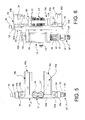
- the oven 1 comprises transport means 8, adapted for moving the preforms along a path inside said oven, and heating means 9.
- the heating means 9 are composed of a plurality of heating modules 10 aligned along the preform path, typically outside the transport means 8.
- Such heating modules 10 comprise for example one or more infrared lamps and suitable reflective surfaces to optimise the output of the lamps.
- the transport means 8 comprise a track 11 which a plurality of mandrels 12 slide on, each adapted for engaging a preform.
- the track 11 comprises two rectilinear sections 13, 13' substantially parallel and two curved sections 14, 14' which connect the rectilinear sections 13, 13' at their ends according to a circular arc route. At the point of said curved sections 14, 14' respective conductor wheels 15, 15' are placed, as will be described further below.
- the track 11 comprises a pair of rails 16a, 16b placed vertically, each in turn divided into rectilinear sections and curved sections at the rectilinear sections and curved sections 13, 13', 14, 14' of the track 11.
- the rails 16a, 16b have an L-shaped cross-section profile, comprising a rack bar 17a, 17b which forms one side of the L and a guide bar 18a, 18b which forms the other side of the L.
- the rack bars 17a, 17b of the rails 16a, 16b are facing, while the relative guide bars 18a, 18b extend in opposite directions on the same vertical plane.
- the rack bars 17a, 17b comprise, on the rectilinear sections 13, 13' of the track 11, a double rack profile 19 separated by a furrow 20, while on the curved sections 14, 14' a single rack is present.
- Such single rack is made in an elastically deformable material, such as polyurethane.
- the guide bar 18a, 18b has a wedge-shaped profile 21 at the apex.
- the first conductor wheel 15 is placed in a distal position in relation to the feed point of the preforms into the oven 1, while the second conductor wheel 15' is placed in correspondence with a release point of the heated preforms from the oven and in a proximal position to the feed point of the preforms into the oven 1,
- the conductor wheels 15, 15' each comprise two pairs of discs.
- the first conductor wheel 15 comprises a pair of lower discs 22a and a pair of upper discs 22b, respectively positioned below and above the rails 16a, 16b and inside the curved section 14 of the track 11.
- the two pairs of lower and upper discs 22a, 22b are associated to the same vertical shaft 23 which is fitted idle to an adequate support (not shown).
- the pair of lower discs 22a comprises a first and a second disc 24, 24', the second disc 24' being distanced above the first disc 24, by means of suitable spacers 25, and having a lesser diameter than that of the first disc 24.
- Both the first and the second disc 24, 24' of the pair of lower discs 22a comprise along their periphery a plurality of semi-circular indentations 26 positioned in sequence, in such a way that the indentations 26 of the first disc 24 are radially aligned with the indentations 26 of the second disc 24'.
- the pair of upper discs 22b comprises a first and a second disc 24", 24"', the second disc 24"' being distanced above the first disc 24", by means of suitable spacers 25, and having a greater diameter than that of the first disc 24".
- the second disc 24"' of the pair of upper discs 22b has the same diameter as the first disc 24 of the pair of lower discs 22a, while the first disc 24" of the pair of upper discs 22b has the same diameter as the second disc 24' of the pair of lower discs 22a.
- Both the first and the second disc 24", 24"' of the pair of upper discs 22b comprise along their periphery a plurality of semi-circular indentations 26 positioned in sequence, in such a way that the indentations 26 of the first disc 24" are radially aligned with the indentations 26 of the second disc 24"' and with the indentations 26 both of the first and the second disc 24, 24' of the pair of lower discs 22a.
- the second conductor wheel 15' similarly comprises a pair of lower discs 27a and a pair of upper discs 27b, respectively positioned below and above the rails 16a, 16b and inside the curved section 14' of the track 11.
- the second conductor wheel 15' is entirely similar to the first conductor wheel 15, except for the fact that the semicircular indentations 26 are positioned at an angular distance from one another which corresponds to the pitch of the notches 4 of the distribution star 3 for the heated preforms.
- Each of the mandrels 12 comprises a housing 28 integral with a sliding support 29.
- the sliding support 29 comprises a forked bar 30 with a C-shaped profile which is placed astride the track 11.
- Said forked bar 30 comprises a vertical plate 30a, from the two ends of which two arms 30b, 30c extend.
- Two cogged teeth 31, 31' are joined to the vertical plate 30a so as to rotate, positioned along a vertical axis between the rack bars 17a, 17b of the rails 16a, 16b in such a way as to engage with each other and with the rack 19 of the respective bars.
- Each of the cogged teeth 31, 31' consists of two coaxial cogged pinions, positioned so as to engage with each other and with the double racks 19 present on the rectilinear sections of the rails. Vice versa, at the curved sections, only the outermost cogged pinion engages with the single rack (see figure 3 ).
- two cylindrical bearings 32a, 32b are fitted so as to rotate on the vertical plate 30a, near the arms 30b, 30c.
- Said bearings 32a, 32b comprise a groove 33 positioned along the cylindrical surface, suitable for engaging in rotation with the respective guide bar 18a, 18b.
- the arms 30b, 30c comprise guide means of the mandrel 12 adapted for engaging with the indentations 26 of the discs 24, 24', 24", 24"' of the conductor wheels 15, 15'.
- Such guide means comprise a first pair of guide castors 34 fitted so as to rotate next to the distal end of the arms 30b, 30c and positioned in such a way as to face one another.
- This first pair of guide castors 34 is destined to interfere with the indentations 26 of the second disc 24' of the pair of lower discs 22a, 27a and with the first disc 24" of the pair of upper discs 22b, 27b of the conductor wheels 15, 15'.
- the guide means further comprise a second pair of guide castors 35 fitted so as to rotate on opposite sides of the arms 30b, 30c, next to the connection point between the arms 30b, 30c and the vertical plate 30a.
- the second pair of guide castors 35 is destined to interfere with the indentations 26 of the first disc 24 of the pair of lower discs 22a, 27a and with the second disc 24"' of the pair of upper discs 22b, 27b of the conductor wheels 15, 15'.
- a thrust wheel 36 is fitted so as to rotate.
- the function of said thrust wheel 36 will be evident from the continuation of the present description.
- the housing 28 of the mandrel 12 houses a gripping finger 37 for a preform P (shown in figure 3 ).
- the gripping finger 37 has a diameter slightly smaller than the inner diameter of the preform P and comprises on the distal portion of its outer surface an engagement portion 37' comprising in turn one or more annular prominences 38 which favour the engagement with the inner neck of the preform.
- annular prominences 38 are made in elastic material such as an elastomer, or are composed of elastic sectors which may radially retract or expand in relation to the cylindrical surface of the gripping finger 37, exerting a retention pressure on the inner surface of the preform.
- the gripping finger 37 further comprises a stem 39 which is inserted in the housing 28 and is vertically mobile.
- a driven body 40 is joined to the stem 39 which projects externally from the housing 28 through a slit 41 positioned vertically on the housing body 28.
- Such driven body 40 typically comprises a wheel adapted for interacting with a cam profile (not shown) which permits the raising or lowering of the gripping finger 37.
- a spiral spring 42 is positioned on the stem 39 and pushes on a shoulder 43 next to the engagement portion 37' of the gripping finger 37. Such spring 42 allows the elastic return downwards of the gripping finger 37.
- the transport means 8 of the oven 1 further comprise drive and distancing means of the mandrels 12.
- Such drive means comprise a first screw 44a positioned at the feed point of the preform into the oven, between the conductor wheel 15' and a first rectilinear section 13 of the track 11; and a second screw 44b positioned at a junction point between the second rectilinear section 13' of the track 11 and said conductor wheel 15'.
- Both screws 44a, 44b comprise a spiral groove 45 of variable pitch destined to interfere with the thrust wheel 36 of each mandrel 12.
- the screws 44a, 44b are fitted in an inverted position in the drive direction of the mandrels 12, in such a way that the first screw 44a has its greatest pitch upstream in the drive direction, while the second screw 44b has its greatest pitch downstream.
- the screws 44a, 44b may be moved independently but in synchrony by respective motors (not shown), or by a single motor equipped with mechanical transmission.
- the preforms are fed into the oven 1 by means of the distributions star 2 shown in figure 1 .
- the gripping finger 37 is raised from the cam and then lowered, thanks to the recall of the spring 42, so as to insert itself in the neck of the preform P and engage with it. From this point on each mandrel 12 bears a preform which is kept in suspension.
- the mandrels 12 with the preforms then pass through the various heating modules 10 of the first rectilinear section 13 and, again, pushed by the first screw 44a, are guided by the conductor wheel 15 passing to the second rectilinear section 13' of the track 11, where the preforms are further heated by the other heating modules 10, until reaching the correct softening temperature of the material.
- the groove 45 has an increasing variable pitch
- the preforms are then picked up by the distribution star 3, but given that the pitch of the screw 44b is the same as that of the star 3, the transfer takes place in constant velocity conditions, that is to say, the preforms do not undergo an acceleration during such transfer.
- the release of the preforms by the mandrels 12 takes place thanks to the fact that the driven body 40 of the mandrels 12 interferes on a suitable cam profile, which causes the raising of the gripping finger 37 in synchrony with the picking up of the preform by the distribution star 3.
- the mandrels 12 deprived of the preforms and distanced at the greater pitch are then guided by the conductor wheel 15' as far as the first screw 44a.
- the latter having a groove 45 with decreasing pitch in the drive direction of the mandrels 12, brings them back to the minimum pitch condition and pushes them along the track 11 in contact with each other.
- the system described makes it possible to maximise the efficiency of the oven in that the mandrels 12 proceed in contact with each other, therefore at the minimum distance possible.
- mandrels 12 are not directly connected to the transport means but are pushed by the two screws 44a, 44b. This permits a significant simplification of the machine and a saving in costs and maintenance times.
- the guide system which comprises the cogged wheels 31, 31' which engage on the double rack bars 17a, 17b, as well as the guide castors 34, 35 destined to engage with the indentations 26 of the conductor wheels 15, 15' permit an efficient control of the position of the mandrels 12, throughout their path, in relation to the oscillations around longitudinal or transversal axes of said mandrel.
- the bearings 32a, 32b also, which slide on the respective guide bars 18a, 18b help to maintain the correct position of the mandrels 12.
- the second screw 44b holds the mandrels 12 at the same pitch as the distribution star 3 which picks up the heated preforms, determining a constant velocity transfer of the same. This entails an absence of acceleration on the preform and thereby avoids their deformation which, as said previously, may have undesirable effects on the final result of the blowing operation.
- the bearings 32a, 32b and the respective guide bars 18a, 18b may be eliminated, without by such jeopardising in an evident manner the stability of the mandrels 12.
Landscapes
- Engineering & Computer Science (AREA)
- Mechanical Engineering (AREA)
- Manufacturing & Machinery (AREA)
- Physics & Mathematics (AREA)
- Thermal Sciences (AREA)
- Blow-Moulding Or Thermoforming Of Plastics Or The Like (AREA)
- Processing And Handling Of Plastics And Other Materials For Molding In General (AREA)
- Heating, Cooling, Or Curing Plastics Or The Like In General (AREA)
Applications Claiming Priority (1)
| Application Number | Priority Date | Filing Date | Title |
|---|---|---|---|
| IT001762A ITMI20111762A1 (it) | 2011-09-30 | 2011-09-30 | Forno per preforme applicabile a macchine soffiatrici o stirosoffiatrici |
Publications (2)
| Publication Number | Publication Date |
|---|---|
| EP2574445A2 true EP2574445A2 (fr) | 2013-04-03 |
| EP2574445A3 EP2574445A3 (fr) | 2014-01-29 |
Family
ID=45094087
Family Applications (1)
| Application Number | Title | Priority Date | Filing Date |
|---|---|---|---|
| EP20120184074 Withdrawn EP2574445A3 (fr) | 2011-09-30 | 2012-09-12 | Four pour préformes applicable à des machines de soufflage ou à des machines d'étirage-soufflage |
Country Status (4)
| Country | Link |
|---|---|
| US (1) | US8851881B2 (fr) |
| EP (1) | EP2574445A3 (fr) |
| CA (1) | CA2789716A1 (fr) |
| IT (1) | ITMI20111762A1 (fr) |
Cited By (3)
| Publication number | Priority date | Publication date | Assignee | Title |
|---|---|---|---|---|
| CN105522716A (zh) * | 2014-10-21 | 2016-04-27 | 克朗斯股份公司 | 用于通过双节距延迟来输送塑料型坯的装置及方法 |
| EP2848382B1 (fr) | 2013-09-13 | 2017-12-13 | Krones AG | Installation de traitement de récipient dotée d'un four et d'un dispositif de formage par soufflage ayant un entraînement individuel des supports des préformes |
| IT201800004215A1 (it) * | 2018-04-05 | 2019-10-05 | Forno per preforme |
Families Citing this family (4)
| Publication number | Priority date | Publication date | Assignee | Title |
|---|---|---|---|---|
| ITMI20120397A1 (it) | 2012-03-14 | 2013-09-15 | Smi Spa | Sistema di manipolazione di oggetti in macchine rotative |
| DE102017004232A1 (de) * | 2017-05-02 | 2018-11-08 | Seidenader Maschinenbau Gmbh | Objekttransportvorrichtung |
| US10926152B2 (en) * | 2019-03-12 | 2021-02-23 | Mak Pickleball, Llc | Storage rack and conveyor for sports equipment |
| CN112693099B (zh) * | 2020-12-09 | 2022-07-26 | 霸州市萱源塑料制品有限公司 | 一种加热及鼓气成型为一体的塑料瓶制造装置 |
Family Cites Families (14)
| Publication number | Priority date | Publication date | Assignee | Title |
|---|---|---|---|---|
| US4265357A (en) * | 1977-04-11 | 1981-05-05 | Owens-Illinois, Inc. | Article infeed gate and control therefor |
| FR2709264B1 (fr) * | 1993-08-26 | 1995-10-27 | Sidel Sa | Installation de fabrication de récipients par soufflage de préformes en matière plastique. |
| CN1140979A (zh) * | 1994-02-15 | 1997-01-22 | 茂林斯公共有限公司 | 可变速输送设备 |
| FR2731176B1 (fr) * | 1995-03-02 | 1997-04-30 | Sidel Sa | Installation de fabrication de recipients par soufflage de preformes en matiere plastique |
| EP0846544A1 (fr) * | 1996-12-03 | 1998-06-10 | BEKUM Maschinenfabriken GmbH | Machine de moulage par soufflage avec dispositif de transport pour aussi changer l'écartement entre les préformes |
| DE19803617C1 (de) * | 1998-01-30 | 1999-08-05 | Kammann Maschf Werner | Vorrichtung zum Dekorieren von Objekten |
| MY130965A (en) * | 2001-07-17 | 2007-07-31 | Frontier Ind Inc | Biaxial stretch blow molding method and apparatus for wide-mouthed containers |
| DE102005011805A1 (de) * | 2005-03-15 | 2007-01-11 | Sig Technology Ltd. | Verfahren und Vorrichtung zur Blasformung von Behältern |
| DE102008023701A1 (de) * | 2008-05-09 | 2009-11-12 | Khs Corpoplast Gmbh & Co. Kg | Vorrichtung zur Blasformung von Behältern |
| IT1396467B1 (it) * | 2008-07-29 | 2012-12-14 | Sacmi | Impianto per il soffiaggio di contenitori di plastica, in particolare bottiglie |
| IT1396853B1 (it) * | 2008-07-29 | 2012-12-20 | Sacmi Coop Mecc Imola Societa' Coop | Unita' di formatura di un impianto per il soffiaggio di contenitori di plastica, in particolare bottiglie |
| IT1396851B1 (it) * | 2008-07-29 | 2012-12-20 | Sacmi | Impianto per il soffiaggio di contenitori di plastica, in particolare bottiglie |
| WO2011040810A1 (fr) * | 2009-09-29 | 2011-04-07 | Van Der Sluis Cigar Machinery B.V. | Appareil de transfert permettant de transférer un article |
| ITMI20120991A1 (it) * | 2012-06-07 | 2013-12-08 | Smi Spa | Sistema di distanziamento e trasferimento di oggetti tra stazioni operative |
-
2011
- 2011-09-30 IT IT001762A patent/ITMI20111762A1/it unknown
-
2012
- 2012-09-12 EP EP20120184074 patent/EP2574445A3/fr not_active Withdrawn
- 2012-09-14 CA CA2789716A patent/CA2789716A1/fr not_active Abandoned
- 2012-09-28 US US13/629,684 patent/US8851881B2/en active Active
Non-Patent Citations (1)
| Title |
|---|
| None |
Cited By (5)
| Publication number | Priority date | Publication date | Assignee | Title |
|---|---|---|---|---|
| EP2848382B1 (fr) | 2013-09-13 | 2017-12-13 | Krones AG | Installation de traitement de récipient dotée d'un four et d'un dispositif de formage par soufflage ayant un entraînement individuel des supports des préformes |
| CN105522716A (zh) * | 2014-10-21 | 2016-04-27 | 克朗斯股份公司 | 用于通过双节距延迟来输送塑料型坯的装置及方法 |
| CN105522716B (zh) * | 2014-10-21 | 2018-03-27 | 克朗斯股份公司 | 用于通过双节距延迟来输送塑料型坯的装置及方法 |
| IT201800004215A1 (it) * | 2018-04-05 | 2019-10-05 | Forno per preforme | |
| EP3549744A1 (fr) * | 2018-04-05 | 2019-10-09 | Smi S.P.A. Con Socio Unico | Four pour préformes |
Also Published As
| Publication number | Publication date |
|---|---|
| EP2574445A3 (fr) | 2014-01-29 |
| US8851881B2 (en) | 2014-10-07 |
| CA2789716A1 (fr) | 2013-03-30 |
| US20130084354A1 (en) | 2013-04-04 |
| ITMI20111762A1 (it) | 2013-03-31 |
Similar Documents
| Publication | Publication Date | Title |
|---|---|---|
| EP2574445A2 (fr) | Four pour préformes applicable à des machines de soufflage ou à des machines d'étirage-soufflage | |
| US9039405B2 (en) | Systems for spacing and transferring objects between operative stations | |
| EP2315654B1 (fr) | Installation pour le moulage par soufflage de contenants en plastique, notamment de bouteilles | |
| CN105492186B (zh) | 用于处理容器的装置的转移站用的同步运行保险装置以及用于容器吹塑成型的装置和方法 | |
| CN102431150B (zh) | 传送预制件的传送设备 | |
| US8202079B2 (en) | Method and device for blow molding containers | |
| US20130243895A1 (en) | System for handling objects in rotary machines | |
| US20160114984A1 (en) | Apparatus and method for transporting plastic preforms with dual pitch delay | |
| US20110278134A1 (en) | Rotary device for the transport of articles | |
| EP3549744B1 (fr) | Four pour préformes | |
| US10786940B2 (en) | Apparatus and method for processing plastic containers, in particular by means of long stators | |
| EP2785509B1 (fr) | Installation pour la fabrication de récipients en matière plastique | |
| EP3199323B1 (fr) | Dispositif de transport de préforme, procédé de transport de préforme, et dispositif de moulage par soufflage | |
| US11376780B2 (en) | Apparatus and method for treating plastic preforms with integrated preform feed | |
| US10065805B2 (en) | Molded article supply apparatus | |
| CN110239064B (zh) | 用于预成型体的烘箱 | |
| US6787096B2 (en) | Device for treating preforms to obtain containers made of plastics | |
| RU2789144C2 (ru) | Печь для разогрева преформ | |
| EP4267370B1 (fr) | Appareil de refroidissement post-moulage pour préformes ou récipients en matière thermoplastique | |
| US11667056B2 (en) | Injection moulding machine for continuous production | |
| CN117140917A (zh) | 热调节预型件的方法 |
Legal Events
| Date | Code | Title | Description |
|---|---|---|---|
| PUAI | Public reference made under article 153(3) epc to a published international application that has entered the european phase |
Free format text: ORIGINAL CODE: 0009012 |
|
| AK | Designated contracting states |
Kind code of ref document: A2 Designated state(s): AL AT BE BG CH CY CZ DE DK EE ES FI FR GB GR HR HU IE IS IT LI LT LU LV MC MK MT NL NO PL PT RO RS SE SI SK SM TR |
|
| AX | Request for extension of the european patent |
Extension state: BA ME |
|
| RIC1 | Information provided on ipc code assigned before grant |
Ipc: B29C 49/42 20060101ALI20130304BHEP Ipc: B65G 29/00 20060101ALI20130304BHEP Ipc: B65G 33/04 20060101ALI20130304BHEP Ipc: B65G 47/84 20060101ALI20130304BHEP Ipc: B29C 49/64 20060101ALN20130304BHEP Ipc: B29C 49/68 20060101ALI20130304BHEP Ipc: B29C 49/36 20060101AFI20130304BHEP |
|
| PUAL | Search report despatched |
Free format text: ORIGINAL CODE: 0009013 |
|
| AK | Designated contracting states |
Kind code of ref document: A3 Designated state(s): AL AT BE BG CH CY CZ DE DK EE ES FI FR GB GR HR HU IE IS IT LI LT LU LV MC MK MT NL NO PL PT RO RS SE SI SK SM TR |
|
| AX | Request for extension of the european patent |
Extension state: BA ME |
|
| RIC1 | Information provided on ipc code assigned before grant |
Ipc: B29C 49/68 20060101ALI20131220BHEP Ipc: B65G 47/84 20060101ALI20131220BHEP Ipc: B29C 49/64 20060101ALN20131220BHEP Ipc: B65G 29/00 20060101ALI20131220BHEP Ipc: B29C 49/42 20060101ALI20131220BHEP Ipc: B29C 49/36 20060101AFI20131220BHEP Ipc: B65G 33/04 20060101ALI20131220BHEP |
|
| 17P | Request for examination filed |
Effective date: 20140221 |
|
| RAX | Requested extension states of the european patent have changed |
Extension state: ME Payment date: 20140221 Extension state: BA Payment date: 20140221 |
|
| RBV | Designated contracting states (corrected) |
Designated state(s): AL AT BE BG CH CY CZ DE DK EE ES FI FR GB GR HR HU IE IS IT LI LT LU LV MC MK MT NL NO PL PT RO RS SE SI SK SM TR |
|
| RIC1 | Information provided on ipc code assigned before grant |
Ipc: B29C 49/64 20060101ALN20150130BHEP Ipc: B65G 33/04 20060101ALI20150130BHEP Ipc: B65G 29/00 20060101ALI20150130BHEP Ipc: B29C 49/68 20060101ALI20150130BHEP Ipc: B29C 49/42 20060101ALI20150130BHEP Ipc: B29C 49/36 20060101AFI20150130BHEP Ipc: B65G 47/84 20060101ALI20150130BHEP |
|
| RIC1 | Information provided on ipc code assigned before grant |
Ipc: B29C 49/36 20060101AFI20150226BHEP Ipc: B29C 49/64 20060101ALN20150226BHEP Ipc: B65G 33/04 20060101ALI20150226BHEP Ipc: B65G 47/84 20060101ALI20150226BHEP Ipc: B29C 49/68 20060101ALI20150226BHEP Ipc: B29C 49/42 20060101ALI20150226BHEP Ipc: B65G 29/00 20060101ALI20150226BHEP |
|
| RIC1 | Information provided on ipc code assigned before grant |
Ipc: B29C 49/42 20060101ALI20150320BHEP Ipc: B65G 33/04 20060101ALI20150320BHEP Ipc: B29C 49/64 20060101ALN20150320BHEP Ipc: B65G 29/00 20060101ALI20150320BHEP Ipc: B65G 47/84 20060101ALI20150320BHEP Ipc: B29C 49/36 20060101AFI20150320BHEP Ipc: B29C 49/68 20060101ALI20150320BHEP |
|
| RIC1 | Information provided on ipc code assigned before grant |
Ipc: B65G 29/00 20060101ALI20150408BHEP Ipc: B29C 49/68 20060101ALI20150408BHEP Ipc: B65G 33/04 20060101ALI20150408BHEP Ipc: B29C 49/36 20060101AFI20150408BHEP Ipc: B29C 49/64 20060101ALN20150408BHEP Ipc: B65G 47/84 20060101ALI20150408BHEP Ipc: B29C 49/42 20060101ALI20150408BHEP |
|
| RIC1 | Information provided on ipc code assigned before grant |
Ipc: B65G 33/04 20060101ALI20150428BHEP Ipc: B29C 49/42 20060101ALI20150428BHEP Ipc: B29C 49/36 20060101AFI20150428BHEP Ipc: B65G 47/84 20060101ALI20150428BHEP Ipc: B29C 49/64 20060101ALN20150428BHEP Ipc: B65G 29/00 20060101ALI20150428BHEP Ipc: B29C 49/68 20060101ALI20150428BHEP |
|
| RIC1 | Information provided on ipc code assigned before grant |
Ipc: B65G 29/00 20060101ALI20150526BHEP Ipc: B29C 49/64 20060101ALN20150526BHEP Ipc: B65G 47/84 20060101ALI20150526BHEP Ipc: B29C 49/68 20060101ALI20150526BHEP Ipc: B65G 33/04 20060101ALI20150526BHEP Ipc: B29C 49/42 20060101ALI20150526BHEP Ipc: B29C 49/36 20060101AFI20150526BHEP |
|
| GRAP | Despatch of communication of intention to grant a patent |
Free format text: ORIGINAL CODE: EPIDOSNIGR1 |
|
| RIC1 | Information provided on ipc code assigned before grant |
Ipc: B29C 49/64 20060101ALN20150622BHEP Ipc: B29C 49/42 20060101ALI20150622BHEP Ipc: B65G 33/04 20060101ALI20150622BHEP Ipc: B65G 47/84 20060101ALI20150622BHEP Ipc: B29C 49/36 20060101AFI20150622BHEP Ipc: B65G 29/00 20060101ALI20150622BHEP Ipc: B29C 49/68 20060101ALI20150622BHEP |
|
| INTG | Intention to grant announced |
Effective date: 20150716 |
|
| RIC1 | Information provided on ipc code assigned before grant |
Ipc: B65G 29/00 20060101ALI20150706BHEP Ipc: B65G 47/84 20060101ALI20150706BHEP Ipc: B65G 33/04 20060101ALI20150706BHEP Ipc: B29C 49/36 20060101AFI20150706BHEP Ipc: B29C 49/68 20060101ALI20150706BHEP Ipc: B29C 49/42 20060101ALI20150706BHEP Ipc: B29C 49/64 20060101ALN20150706BHEP |
|
| STAA | Information on the status of an ep patent application or granted ep patent |
Free format text: STATUS: THE APPLICATION IS DEEMED TO BE WITHDRAWN |
|
| 18D | Application deemed to be withdrawn |
Effective date: 20151127 |