EP2574516A2 - Appareil de commande pour véhicule hybride - Google Patents
Appareil de commande pour véhicule hybride Download PDFInfo
- Publication number
- EP2574516A2 EP2574516A2 EP20120185872 EP12185872A EP2574516A2 EP 2574516 A2 EP2574516 A2 EP 2574516A2 EP 20120185872 EP20120185872 EP 20120185872 EP 12185872 A EP12185872 A EP 12185872A EP 2574516 A2 EP2574516 A2 EP 2574516A2
- Authority
- EP
- European Patent Office
- Prior art keywords
- gear shift
- driving
- battery
- assist
- assist control
- Prior art date
- Legal status (The legal status is an assumption and is not a legal conclusion. Google has not performed a legal analysis and makes no representation as to the accuracy of the status listed.)
- Withdrawn
Links
Images

Classifications
-
- B—PERFORMING OPERATIONS; TRANSPORTING
- B60—VEHICLES IN GENERAL
- B60W—CONJOINT CONTROL OF VEHICLE SUB-UNITS OF DIFFERENT TYPE OR DIFFERENT FUNCTION; CONTROL SYSTEMS SPECIALLY ADAPTED FOR HYBRID VEHICLES; ROAD VEHICLE DRIVE CONTROL SYSTEMS FOR PURPOSES NOT RELATED TO THE CONTROL OF A PARTICULAR SUB-UNIT
- B60W20/00—Control systems specially adapted for hybrid vehicles
- B60W20/30—Control strategies involving selection of transmission gear ratio
-
- B—PERFORMING OPERATIONS; TRANSPORTING
- B60—VEHICLES IN GENERAL
- B60K—ARRANGEMENT OR MOUNTING OF PROPULSION UNITS OR OF TRANSMISSIONS IN VEHICLES; ARRANGEMENT OR MOUNTING OF PLURAL DIVERSE PRIME-MOVERS IN VEHICLES; AUXILIARY DRIVES FOR VEHICLES; INSTRUMENTATION OR DASHBOARDS FOR VEHICLES; ARRANGEMENTS IN CONNECTION WITH COOLING, AIR INTAKE, GAS EXHAUST OR FUEL SUPPLY OF PROPULSION UNITS IN VEHICLES
- B60K6/00—Arrangement or mounting of plural diverse prime-movers for mutual or common propulsion, e.g. hybrid propulsion systems comprising electric motors and internal combustion engines
- B60K6/20—Arrangement or mounting of plural diverse prime-movers for mutual or common propulsion, e.g. hybrid propulsion systems comprising electric motors and internal combustion engines the prime-movers consisting of electric motors and internal combustion engines, e.g. HEVs
- B60K6/50—Architecture of the driveline characterised by arrangement or kind of transmission units
- B60K6/54—Transmission for changing ratio
- B60K6/543—Transmission for changing ratio the transmission being a continuously variable transmission
-
- B—PERFORMING OPERATIONS; TRANSPORTING
- B60—VEHICLES IN GENERAL
- B60W—CONJOINT CONTROL OF VEHICLE SUB-UNITS OF DIFFERENT TYPE OR DIFFERENT FUNCTION; CONTROL SYSTEMS SPECIALLY ADAPTED FOR HYBRID VEHICLES; ROAD VEHICLE DRIVE CONTROL SYSTEMS FOR PURPOSES NOT RELATED TO THE CONTROL OF A PARTICULAR SUB-UNIT
- B60W10/00—Conjoint control of vehicle sub-units of different type or different function
- B60W10/02—Conjoint control of vehicle sub-units of different type or different function including control of driveline clutches
-
- B—PERFORMING OPERATIONS; TRANSPORTING
- B60—VEHICLES IN GENERAL
- B60W—CONJOINT CONTROL OF VEHICLE SUB-UNITS OF DIFFERENT TYPE OR DIFFERENT FUNCTION; CONTROL SYSTEMS SPECIALLY ADAPTED FOR HYBRID VEHICLES; ROAD VEHICLE DRIVE CONTROL SYSTEMS FOR PURPOSES NOT RELATED TO THE CONTROL OF A PARTICULAR SUB-UNIT
- B60W10/00—Conjoint control of vehicle sub-units of different type or different function
- B60W10/04—Conjoint control of vehicle sub-units of different type or different function including control of propulsion units
- B60W10/06—Conjoint control of vehicle sub-units of different type or different function including control of propulsion units including control of combustion engines
-
- B—PERFORMING OPERATIONS; TRANSPORTING
- B60—VEHICLES IN GENERAL
- B60W—CONJOINT CONTROL OF VEHICLE SUB-UNITS OF DIFFERENT TYPE OR DIFFERENT FUNCTION; CONTROL SYSTEMS SPECIALLY ADAPTED FOR HYBRID VEHICLES; ROAD VEHICLE DRIVE CONTROL SYSTEMS FOR PURPOSES NOT RELATED TO THE CONTROL OF A PARTICULAR SUB-UNIT
- B60W10/00—Conjoint control of vehicle sub-units of different type or different function
- B60W10/04—Conjoint control of vehicle sub-units of different type or different function including control of propulsion units
- B60W10/08—Conjoint control of vehicle sub-units of different type or different function including control of propulsion units including control of electric propulsion units, e.g. motors or generators
-
- B—PERFORMING OPERATIONS; TRANSPORTING
- B60—VEHICLES IN GENERAL
- B60W—CONJOINT CONTROL OF VEHICLE SUB-UNITS OF DIFFERENT TYPE OR DIFFERENT FUNCTION; CONTROL SYSTEMS SPECIALLY ADAPTED FOR HYBRID VEHICLES; ROAD VEHICLE DRIVE CONTROL SYSTEMS FOR PURPOSES NOT RELATED TO THE CONTROL OF A PARTICULAR SUB-UNIT
- B60W10/00—Conjoint control of vehicle sub-units of different type or different function
- B60W10/10—Conjoint control of vehicle sub-units of different type or different function including control of change-speed gearings
- B60W10/11—Stepped gearings
-
- B—PERFORMING OPERATIONS; TRANSPORTING
- B60—VEHICLES IN GENERAL
- B60W—CONJOINT CONTROL OF VEHICLE SUB-UNITS OF DIFFERENT TYPE OR DIFFERENT FUNCTION; CONTROL SYSTEMS SPECIALLY ADAPTED FOR HYBRID VEHICLES; ROAD VEHICLE DRIVE CONTROL SYSTEMS FOR PURPOSES NOT RELATED TO THE CONTROL OF A PARTICULAR SUB-UNIT
- B60W10/00—Conjoint control of vehicle sub-units of different type or different function
- B60W10/24—Conjoint control of vehicle sub-units of different type or different function including control of energy storage means
- B60W10/26—Conjoint control of vehicle sub-units of different type or different function including control of energy storage means for electrical energy, e.g. batteries or capacitors
-
- B—PERFORMING OPERATIONS; TRANSPORTING
- B60—VEHICLES IN GENERAL
- B60W—CONJOINT CONTROL OF VEHICLE SUB-UNITS OF DIFFERENT TYPE OR DIFFERENT FUNCTION; CONTROL SYSTEMS SPECIALLY ADAPTED FOR HYBRID VEHICLES; ROAD VEHICLE DRIVE CONTROL SYSTEMS FOR PURPOSES NOT RELATED TO THE CONTROL OF A PARTICULAR SUB-UNIT
- B60W20/00—Control systems specially adapted for hybrid vehicles
- B60W20/10—Controlling the power contribution of each of the prime movers to meet required power demand
- B60W20/15—Control strategies specially adapted for achieving a particular effect
- B60W20/19—Control strategies specially adapted for achieving a particular effect for achieving enhanced acceleration
-
- B—PERFORMING OPERATIONS; TRANSPORTING
- B60—VEHICLES IN GENERAL
- B60W—CONJOINT CONTROL OF VEHICLE SUB-UNITS OF DIFFERENT TYPE OR DIFFERENT FUNCTION; CONTROL SYSTEMS SPECIALLY ADAPTED FOR HYBRID VEHICLES; ROAD VEHICLE DRIVE CONTROL SYSTEMS FOR PURPOSES NOT RELATED TO THE CONTROL OF A PARTICULAR SUB-UNIT
- B60W30/00—Purposes of road vehicle drive control systems not related to the control of a particular sub-unit, e.g. of systems using conjoint control of vehicle sub-units
- B60W30/18—Propelling the vehicle
- B60W30/19—Improvement of gear change, e.g. by synchronisation or smoothing gear shift
-
- B—PERFORMING OPERATIONS; TRANSPORTING
- B60—VEHICLES IN GENERAL
- B60K—ARRANGEMENT OR MOUNTING OF PROPULSION UNITS OR OF TRANSMISSIONS IN VEHICLES; ARRANGEMENT OR MOUNTING OF PLURAL DIVERSE PRIME-MOVERS IN VEHICLES; AUXILIARY DRIVES FOR VEHICLES; INSTRUMENTATION OR DASHBOARDS FOR VEHICLES; ARRANGEMENTS IN CONNECTION WITH COOLING, AIR INTAKE, GAS EXHAUST OR FUEL SUPPLY OF PROPULSION UNITS IN VEHICLES
- B60K6/00—Arrangement or mounting of plural diverse prime-movers for mutual or common propulsion, e.g. hybrid propulsion systems comprising electric motors and internal combustion engines
- B60K6/20—Arrangement or mounting of plural diverse prime-movers for mutual or common propulsion, e.g. hybrid propulsion systems comprising electric motors and internal combustion engines the prime-movers consisting of electric motors and internal combustion engines, e.g. HEVs
- B60K6/42—Arrangement or mounting of plural diverse prime-movers for mutual or common propulsion, e.g. hybrid propulsion systems comprising electric motors and internal combustion engines the prime-movers consisting of electric motors and internal combustion engines, e.g. HEVs characterised by the architecture of the hybrid electric vehicle
- B60K6/48—Parallel type
- B60K2006/4808—Electric machine connected or connectable to gearbox output shaft
-
- B—PERFORMING OPERATIONS; TRANSPORTING
- B60—VEHICLES IN GENERAL
- B60W—CONJOINT CONTROL OF VEHICLE SUB-UNITS OF DIFFERENT TYPE OR DIFFERENT FUNCTION; CONTROL SYSTEMS SPECIALLY ADAPTED FOR HYBRID VEHICLES; ROAD VEHICLE DRIVE CONTROL SYSTEMS FOR PURPOSES NOT RELATED TO THE CONTROL OF A PARTICULAR SUB-UNIT
- B60W2510/00—Input parameters relating to a particular sub-units
- B60W2510/24—Energy storage means
- B60W2510/242—Energy storage means for electrical energy
- B60W2510/244—Charge state
-
- B—PERFORMING OPERATIONS; TRANSPORTING
- B60—VEHICLES IN GENERAL
- B60Y—INDEXING SCHEME RELATING TO ASPECTS CROSS-CUTTING VEHICLE TECHNOLOGY
- B60Y2400/00—Special features of vehicle units
- B60Y2400/70—Gearings
- B60Y2400/71—Manual or semi-automatic, e.g. automated manual transmissions
-
- Y—GENERAL TAGGING OF NEW TECHNOLOGICAL DEVELOPMENTS; GENERAL TAGGING OF CROSS-SECTIONAL TECHNOLOGIES SPANNING OVER SEVERAL SECTIONS OF THE IPC; TECHNICAL SUBJECTS COVERED BY FORMER USPC CROSS-REFERENCE ART COLLECTIONS [XRACs] AND DIGESTS
- Y02—TECHNOLOGIES OR APPLICATIONS FOR MITIGATION OR ADAPTATION AGAINST CLIMATE CHANGE
- Y02T—CLIMATE CHANGE MITIGATION TECHNOLOGIES RELATED TO TRANSPORTATION
- Y02T10/00—Road transport of goods or passengers
- Y02T10/60—Other road transportation technologies with climate change mitigation effect
- Y02T10/62—Hybrid vehicles
-
- Y—GENERAL TAGGING OF NEW TECHNOLOGICAL DEVELOPMENTS; GENERAL TAGGING OF CROSS-SECTIONAL TECHNOLOGIES SPANNING OVER SEVERAL SECTIONS OF THE IPC; TECHNICAL SUBJECTS COVERED BY FORMER USPC CROSS-REFERENCE ART COLLECTIONS [XRACs] AND DIGESTS
- Y10—TECHNICAL SUBJECTS COVERED BY FORMER USPC
- Y10S—TECHNICAL SUBJECTS COVERED BY FORMER USPC CROSS-REFERENCE ART COLLECTIONS [XRACs] AND DIGESTS
- Y10S903/00—Hybrid electric vehicles, HEVS
- Y10S903/902—Prime movers comprising electrical and internal combustion motors
- Y10S903/903—Prime movers comprising electrical and internal combustion motors having energy storing means, e.g. battery, capacitor
- Y10S903/93—Conjoint control of different elements
Definitions
- This disclosure generally relates to a control apparatus of a hybrid vehicle.
- a hybrid vehicle including an engine that is operated by a combustion energy of fuel and an electric motor that is operated by an electric energy has been variously developed.
- the engine and the electric motor serve as power sources in a driving state of the hybrid vehicle.
- the hybrid vehicle has lately attracted the attention because noise and air contamination, for example, are avoidable by the electric motor mainly serving as the power source in a normal driving state of the hybrid vehicle.
- disadvantages of an electric vehicle specifically, difficulties in a sudden acceleration, a high-load driving, and a high-speed driving caused by an insufficient mileage by one charge of battery or less torque generation, for example, may be eliminated by a combination use of the engine operated by the combustion energy.
- the hybrid vehicle in order to selectively use the engine and the electric motor depending on a driving state of the hybrid vehicle, includes plural driving modes in which each of the engine and the motor operates differently.
- the plural driving modes include an engine driving mode in which the hybrid vehicle is driven only by the engine as the power source, a motor driving mode in which the hybrid vehicle is driven only by the electric motor as the power source, and an engine and motor driving mode in which the hybrid vehicle is driven by both the engine and the electric motor as the power sources, for example.
- the driving mode of the hybrid vehicle is automatically switchable depending on a mode switch condition that is specified beforehand, i.e., a power source map, for example, where the driving state of the hybrid vehicle including a vehicle speed and an accelerator operation amount serves as a parameter.
- a hybrid vehicle disclosed in JP10-28302A (which will be hereinafter referred to as Reference 1) includes a residue determining means for determining whether or not a total energy residue of an engine and an electric motor or an energy residue of the engine is equal to or smaller than a threshold value, and a mode switching means for switching each of the operating conditions of the engine and the electric motor to a mileage increase mode in which a mileage of the hybrid vehicle increases.
- an automated manual transmission (which will be hereinafter referred to as an AMT) obtained by attaching an actuator to a known manual transmission is known to automatically perform a gear shift operation including an engagement/disengagement of a clutch and a gear shifting based on an intention of a vehicle driver or a vehicle state.
- an ATM in a state where the clutch is in a disengagement state during the gear shifting, a torque from the engine (an engine torque) is not transmitted to wheels.
- an engine torque an engine torque
- a gear shift assist is performed so as to apply a driving torque of the electric motor to the wheels as an assist in the disengagement state of the clutch. Then, the loss of acceleration feeling, for example, is avoidable.
- a driving assist where the driving torque from the electric motor is applied to the wheels as the assist of the engine torque is conducted for the purpose of energy saving.
- the gear shift assist where the driving torque of the electric motor is applied to the wheels in the disengagement state of the clutch during the gear shifting is impossible in a case where the energy residue of the electric motor (i.e., an SOC value of the battery) is reduced.
- a gear shift feeling may be drastically deteriorated (a loss of acceleration feeling or a gear shift shock, for example).
- a control apparatus of a hybrid vehicle includes an automatic transmission including an input shaft driven to rotate by an engine torque of an engine mounted at a hybrid vehicle, an output shaft rotatably connected to driving wheels, and a plurality of gear sets configured to connect the input shaft and the output shaft to be rotatable at different gear ratios, the automatic transmission including a changing device (34, 36) that selects one of the plurality of gear sets to cause the selected one of the plurality of gear sets to be rotatably connected to the input shaft and the output shaft, a gear shift operation control device controlling a gear shift operation of the automatic transmission, a clutch being switchable by a clutch driving device between an engagement state where an output shaft of the engine and the input shaft of the automatic transmission are rotatably connected to each other and a disengagement state where the connection between the output shaft of the engine and the input shaft of the automatic transmission is released, a motor rotatably connected to the driving wheels, a battery connected to the motor, a driving assist control device performing a driving assist control by
- the operation mode of the hybrid vehicle is switched to the battery preserving mode in a case where the SOC value of the battery supplying an electric power to the motor is equal to or smaller than the first predetermined value to thereby stop the driving assist that has been performed in the normal mode. Then, the electric power for the driving assist is preserved to thereby reduce a power consumption of the battery.
- the gear shift assist at the time of the gear shift operation of the hybrid vehicle is continuously performed so as to inhibit a deterioration of a gear shift feeling caused by a torque fluctuation at the time of the gear shift operation of the hybrid vehicle.
- the control apparatus further includes a second mode switch device switching the operation mode from the battery power preserving mode to an assist prohibition mode in which the driving assist control and the gear shift assist control are prohibited in a case where the SOC value is equal to or smaller than a second predetermined value that is smaller than the first predetermined value.
- the assist control is totally prohibited relative to the output shaft of the engine by the assist prohibition mode in a case where the SOC value of the battery is equal to or smaller than the second predetermined value that is smaller than the first predetermined value.
- the power supply from the battery for the assist control is stopped.
- the power consumption of the battery is sopped to thereby inhibit an excess discharge of the battery thereafter.
- the control apparatus further includes a warning device informing a passenger in the hybrid vehicle that the operation mode is switched to the assist prohibition mode.
- a passenger of the hybrid vehicle is informed that the operation mode is changed to the assist prohibition mode by the warning device to thereby inhibit the passenger from feeling frightened or anxiety because of the change of the gear shift feeling.
- the control apparatus further includes a gear shift feeling deterioration inhibition device easing a torque fluctuation that occurs in association with a torque drop during the gear shift operation in a case where the gear shift assist control is prohibited.
- the gear shift operation by the automatic transmission is brought into the gear shift feeling deterioration inhibition mode to thereby decrease the torque drop because of the impossibility of the gear shift assist by the motor and the deterioration of the passenger's feeling because of the gear shift shock.
- the control apparatus further includes a gear shift feeling deterioration inhibition device easing a torque fluctuation that occurs in association with a torque drop during the gear shift operation in a case where the gear shift assist control is prohibited.
- the operation mode is switched to the battery power preserving mode in which the driving assist control device prohibits the driving assist control and permits the gear shift assist control in a case where the SOC value is greater than the second predetermined value.
- the operation mode of the hybrid vehicle is switched to the battery preserving mode to thereby stop the driving assist that has been performed in the normal mode. Then, the electric power for the driving assist is preserved to thereby reduce the power consumption of the battery.
- the gear shift assist at the time of the gear shift operation of the hybrid vehicle is continuously performed so as to inhibit the deterioration of the gear shift feeling caused by the torque fluctuation at the time of the gear shift operation of the hybrid vehicle.
- the first predetermined value is 50% and the second predetermined value is 40%.
- the operation mode of the hybrid vehicle is switched to the battery preserving mode in a case where the SOC value of the battery supplying the electric power to the motor is equal to or smaller than the first predetermined value to thereby stop the driving assist that has been performed in the normal mode. Then, the electric power for the driving assist is preserved to thereby reduce the power consumption of the battery.
- the gear shift assist at the time of the gear shift operation of the hybrid vehicle is continuously performed so as to inhibit the deterioration of the gear shift feeling caused by the torque fluctuation at the time of the gear shift operation of the hybrid vehicle.
- the gear shift feeling deterioration inhibition device reduces a shifting time period after which a gear position of the automatic transmission is changed to a next gear position.
- a time period during which the torque drop occurs, the torque drop causing a driver to feel like the clutch device is brought into the disengagement state, may be reduced.
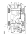
- Fig. 1 is a schematic view of a hybrid vehicle using a control apparatus according to an embodiment disclosed here;
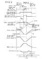
- Fig. 2 is a time chart of a gear shift operation according to the embodiment
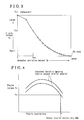
- Fig. 3 is a map illustrating a relationship between a clutch torque and an actuator operation amount according to the embodiment
- Fig. 4 is a graph illustrating a relationship between an engine torque and an engine revolutions when an engine output control amount is constant according to the embodiment
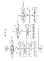
- Fig. 5 is a flowchart performed by the control apparatus according to the embodiment.
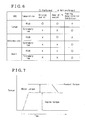
- Fig. 6 is a table illustrating an execution of a driving assist, a gear shift assist, and a gear shift feeling deterioration inhibition depending on a battery condition;
- Fig. 7 is a graph illustrating a motor torque when the driving assist is performed.
- Fig. 8 is a graph illustrating a gear shift line when a gear position is changed.
- a hybrid vehicle 2 (which will be hereinafter simply referred to as a vehicle 2) includes two power generating machines, i.e., an engine 4 and a motor 8 which is driven by an electric power stored in a battery 6.
- the engine 4 and the motor 8 that are arranged in parallel with each other drive wheels of the vehicle 2.
- the motor 8 is also used as a generator (a motor generator MG).
- An automated manual transmission (AMT) 12 serving as an automatic transmission is connected to the engine 4 via a clutch device 16 serving as a clutch.
- the clutch device 16 is provided between an input shaft 14 of the automated manual transmission 12 and an output shaft 10 of the engine 4.
- the clutch device 16 engages and disengages between the output shaft 10 of the engine 4 and the input shaft 14 of the automated manual transmission 12 so as to control a transmission of an engine torque Te to the automated manual transmission 12.
- the vehicle 2 also includes a differential 18, a drive shaft 20, and driving wheels 22.
- the vehicle 2 further includes a HV ECU (a hybrid vehicle electronic control unit) 24, a MG ECU (a motor generator electronic control unit) 26, an inverter 28, an ENG ECU (an engine electronic control unit) 30, an AMT ECU (an automated manual transmission electronic control unit) 38, and a battery ECU (a battery electronic control unit) 40.
- the HV ECU 24 entirely controls the vehicle 2.
- the MG ECU 26 sends a command to the motor 8 to be driven or regenerated.
- the inverter 28 converts a direct current of the battery 6 into an alternating current that is supplied to the motor 8.
- the ENG ECU 30 controls the engine 4 to stop or burn fuel.
- the AMT ECU 38 serves as a gear shift operation control device connected to a clutch actuator 32 serving as a clutch driving device, a shift actuator 34, and a select actuator 36 all of which are incorporated in the automated manual transmission 12 so as to perform an optimum gear shift operation by controlling the clutch actuator 32, the shift actuator 34, and the select actuator 36.
- the battery ECU 40 controls a charging condition of the battery 6 connected to the inverter 28.
- the shift actuator 34 and the select actuator 36 constitute a changing device.
- the MG ECU 26, the ENG ECU 30, the AMT ECU 38, and the battery ECU 40 are controlled by the HV ECU 24.
- Each of the HV ECU 24, the MG ECU 26, the ENG ECU 30, the AMT ECU 38, and the battery ECU 40 includes a control portion constituted by, for example, a CPU performing a calculation, a ROM, a RAM, and an EEPROM which stores data without a backup power source.
- the control portion performs a calculation process based on various control programs and maps stored in the ROM by the CPU.
- the ROM stores the various control programs and the maps referred to when the aforementioned control programs are executed.
- the RAM temporarily stores a calculation result of the control portion and data input from the outside, for example.
- the EEPROM includes a nonvolatile memory for storing data.
- the CPU, the ROM, the RAM, and the EEPROM of the control portion are connected to one another via a bus and connected to an input interface and an output interface.
- Various sensors including an engine speed sensor 44, a battery temperature sensor 46 serving as a battery temperature detection device, and an SOC value detection sensor 48 serving as an SOC value detection device are connected to the HV ECU 24 via the MG ECU 26, the ENG ECU 30, the AMT ECU 38, and the battery ECU 40.
- the engine 4 includes a throttle valve 50 adjusting an intake air volume to control an output of the engine 4, a throttle sensor 52 detecting an opening of the throttle valve 50 (a throttle opening), and a throttle actuator 54 opening and closing the throttle valve 50.
- the throttle sensor 52 and the throttle actuator 54 are connected to the ENG ECU 30.
- the ENG ECU 30 drives a starter 42 to start the engine 4.
- the engine speed sensor 44 is provided in the vicinity of the output shaft 10 of the engine 4 so as to detect revolutions of the output shaft 10.
- An accelerator opening sensor 57 is provided at an accelerator pedal 55 so as to detect a depression amount of the accelerator pedal 55.
- a driving torque desired for the driving wheels 22 is determined on a basis of an accelerator opening detected by the accelerator opening sensor 57.
- an accelerator opening signal is transmitted from the accelerator opening sensor 57 to the HV ECU 24.
- the HV ECU 24 transmits a command value as the driving torque to the ENG ECU 30 depending on the value of the accelerator opening signal transmitted to the HV ECU 24.
- the ENG ECU 30 operates the throttle actuator 54 based on the command value so as to open and close the throttle valve 50.
- the ENG ECU 30 controls the output and engine revolutions (an engine speed) Ne of the engine 4 while the engine speed sensor 44 is monitoring the revolutions of the output shaft 10.
- the engine revolutions Ne are also controllable by an operation of the throttle actuator 54 based on a request from the HV ECU 24, regardless of the depression amount of the accelerator pedal 55
- the HV ECU 24 sends a command to the ENG ECU 30 to generate a driver request torque Tdrv, which is obtained by a conversion of the driving torque desired for the driving wheels 22 into the engine torque Te,.
- the magnitude of the driving torque varies depending on a gear ratio between the input shaft 14 and an output shaft 15 of the automated manual transmission 12, for example. Therefore, the conversion of the driving torque is performed on a basis of the output shaft 10 of the engine 4 serving as a reference point and then the driver request torque Tdrv is instructed to the ENG ECU 30.
- a power generation torque driving the motor 8 and an assist torque generated by the motor 8 will be explained as values obtained on a basis of the aforementioned reference point.
- the clutch device 16 includes, for example, a flywheel fixed to the output shaft 10 of the engine 4, a clutch disc spline-connected to the input shaft 14 of the automated manual transmission 12 so as to integrally rotate therewith, and a clutch assembly fixed to the flywheel.
- a press-contact load of the clutch disc relative to the fly wheel is changed to thereby increase and decrease a rotation transmission amount between the flywheel and the clutch disc.
- a clutch torque Tc of the clutch device 16 is controllable to a target clutch torque requested by the HV ECU 24 depending on a driving state of the vehicle 2.
- the target clutch torque is achieved by the AMT ECU 38 that is controlled by a command from the HV ECU 24 to control an operation amount of the clutch actuator 32 operating the clutch device 16 based on a map illustrating a relationship between the clutch torque Tc and an actuator operation amount Sa illustrated in Fig. 3 .
- the clutch actuator 32 constitutes a clutch driving device.
- the automated manual transmission 12 is obtained by a known manual transmission to which the clutch device 16 that is controlled between an engagement state and a disengagement state by the operation of the clutch actuator 32, for example, is attached to thereby achieve an automatic gear shift operation.
- the automated manual transmission 12 includes the shift actuator 34 and the select actuator 36 serving as the changing device for selectively meshing or connecting one of the plural gear sets 33.
- a method for driving the shift actuator 34 and the select actuator 36 is known (for example, refer to JP2004-176894A ) and thus a detailed explanation thereof will be omitted.
- the input shaft 14 of the automated manual transmission 12 is connected to the output shaft 10 of the engine 4 via the clutch device 16 so as to be engageable and disengageable relative to the output shaft 10.
- the output shaft 15 of the automated manual transmission 12 is connected to the drive shaft 20 via the differential 18 so that a driving force of the output shaft 15 is transmittable to the drive shaft 20 (see Fig. 1 ). Accordingly, the engine torque Te is controlled to increase or decrease by gears (the gear sets 33) of the automated manual transmission 12 and is transmitted to the drive shaft 20 via the differential 18 to thereby drive the vehicle 2.
- the motor 8, which is connected to the differential 18, is a three-phase alternating current synchronous motor, for example, used in a general hybrid vehicle.
- a rotor shaft of the motor 8 is rotatably connected to an input side of the differential 18 via a deceleration mechanism. That is, the rotor shaft of the motor 8 is rotatably connected to both the output shaft 15 of the automated manual transmission 12 and the driving wheels 22.
- the inverter 28 and the battery 6 are connected to the motor 8.
- the inverter 28 includes an AC terminal and a DC terminal serving as input and output terminals. The AC terminal is connected to a power supply terminal of the motor 8 while the DC terminal is connected to a terminal of the battery 6.
- the inverter 28 includes a direct current to alternating current conversion function for converting the direct current output from the battery 6 into the alternating current with variable frequencies so as to supply the alternating current to the motor 8, and an alternating current to direct current conversion function for converting AC power generated at the motor 8 into DC power so that the battery 6 is charged.
- the MG ECU 26 controls the inverter 28 to thereby drive the motor 8 and perform a torque assist relative to the drive shaft 20.
- the motor 8 is used as the generator, the battery 6 is charged with a regenerated energy generated by the motor 8.
- the SOC value detection sensor 48 is provided at the battery 6 so that the battery ECU 40 controls the charging condition of the battery 6 based on an SOC value (a state of charge value) detected by the SOC value detection sensor 48.
- Fig. 2 illustrates the time chart of the gear shift operation from the 1 st gear to the 2 nd gear, for example.
- a horizontal axis in Fig. 2 indicates time while a vertical axis indicates, from the upper side in Fig. 2 , gear positions, a flag indicating an execution of the gear shift operation, a gear position change, engine revolutions (input shaft revolutions), the clutch torque Tc, the engine torque Te (the driver request torque Tdrv), a motor torque Tm, and the acceleration of the vehicle 2.
- the gear shift operation is started from time t1 and is completed at time t4.
- the time chart in Fig. 2 indicates a case where the driver of the vehicle 2 intends to accelerate the vehicle 2 and depresses the accelerator pedal 55 at a constant level during the gear shift operation.
- the AMT ECU 38 includes a gear shift line specified for each gear position as illustrated in Fig. 8 .
- a flag indicating an execution of the gear shift operation is turned on at the HV ECU 24 by a command from the AMT ECU 38 to thereby start the control of the gear shift operation.
- the automated manual transmission 12 causes the clutch actuator 32 to operate at time t1 by the command from the AMT ECU 38.
- the clutch actuator 32 disengages between the flywheel and the clutch disc of the clutch device 16 by time 2.
- the clutch device 16 is in a fully disengagement state during a time period from time t2 to time t3
- the AMT ECU 38 appropriately drives the shift actuator 34 and the select actuator 36 so as to change the gear position of the automated manual transmission 12.
- the ENG ECU 30 drives the throttle actuator 54 and operates the throttle valve 50 so that the engine revolutions Ne are compatible with input shaft revolutions Ni of the automated manual transmission 12 based on the gear position after changing and the vehicle speed at that time.
- the clutch device 16 generates a partial engagement state while gradually increasing the clutch torque Tc by driving the clutch actuator 32 so that the engine revolutions Ne are appropriately compatible with the input shaft revolutions Ni at the gear position after changing.
- the clutch device 16 is eventually brought into a fully engagement state to thereby finish the gear shift operation at time t4.
- the MG ECU 26 drives the motor 8 so as to start generating the assist torque.
- the engine torque Te decreases while the MG ECU 26 generates the assist torque corresponding to the decrease of the engine torque Te.
- the assist torque generated in the aforementioned manner corresponds to a difference obtained by subtracting the driving torque by the engine 4 from the driver request torque Tdrv within a range not exceeding the driver request torque Tdrv.
- the generation of the assist torque gradually decreases and stops.
- the assist torque generated by the motor 8 from time t1 to time t4 is transmitted to the driving wheels 22 via the differential 18. Accordingly, the control of the gear shift operation by the HV ECU 24, the MG ECU 26, and the AMT ECU 38 is completed.
- a driving assist by the motor 8 is achieved by the assist torque (the motor torque) serving as a difference between the request torque by the driver and the estimated engine torque Te as illustrated in Fig. 7 while the estimated engine torque Te is obtained by a map illustrating a relationship between the throttle opening and the engine revolutions as illustrated in Fig. 4 .
- the assist torque is transmitted to the driving wheels 22 via the differential 18.
- the HV ECU 24 determines whether or not the temperature of the battery 6 is equal to or greater than a predetermined temperature based on a detection signal of the battery temperature sensor 46 in step 1 (i.e., S1, hereinafter “step” will be abbreviated to "S").
- the predetermined temperature is specified in view of types, capacity, and characteristics of the battery. For example, the predetermined temperature is specified to be -15 degrees that is stored at the ROM in the HV ECU 24 beforehand.
- the temperature of the battery 6 is first detected.
- the HV ECU 24 changes an operation mode of the vehicle 2 to an assist prohibition mode in S2 and transmits a command to the MG ECU 26 so as to stop the power supply to the motor 8.
- the driving assist and a gear shift assist by the motor 8 relative to the engine torque are prohibited in S3. That is, the power supply from the battery 6 is stopped.
- S2 in Fig. 5 serves as a third mode switch device for switching the operation mode to the assist prohibition mode by the HV ECU 24.
- a warning display (a warning device) is conducted to draw the driver's attention by indicating that the gear shift assist is not performed in S4.
- a blinking display of a specific mark lamp for example, is used as the warning display.
- the warning display may inhibit the driver of the vehicle 2 from feeling discomfort and further having an anxiety feeling in a case where the assist relative to a fluctuation in the engine torque is not performed at a time of the gear shift operation.
- a gear shift feeling deterioration inhibition is performed in S5. That is, the operation mode of the vehicle 2 is changed to a gear shift feeling deterioration inhibition mode in S5. As illustrated in Fig. 6 , in a case where the temperature of the battery 6 is extremely low, the gear shift feeling deterioration inhibition is performed as indicated by a round mark. According to a first example of the feeling deterioration inhibition, time T (a shifting time period) after which the gear position is changed to the next position is shortened. Accordingly, a time period during which a torque drop occurs, the torque drop causing the driver to feel like the clutch device 16 is brought into the disengagement state, may be reduced. S5 serves as a gear shift feeling deterioration inhibition device.
- a recovery from a torque down state in a case where the clutch device 16 in the disengagement state is brought into the engagement state may be smoothened.
- a line SL (see Fig. 2 ) indicated by the clutch torque Tc in a state where the clutch device 16 is changed from the disengagement state to the engagement state is gently inclined.
- an acceleration change is made gentle so as to ease a shift shock in a state where the clutch device 16 is brought into the engagement state from the disengagement state.
- a shift point at which the gear position is changed i.e., the gear shift line specified for each gear position
- the shift timing is slow to thereby increase the engine revolutions at the time of the gear shift operation.
- the engine torque decreases in association with the increase of the engine revolutions after the engine revolutions increase by a predetermined amount or more in a state where the throttle opening is constant (which is indicated by an engine torque Tea and an actual engine revolutions RNe in Fig. 4 ).
- the decrease of the engine torque at the time of the gear shift operation inhibits the increase of the torque transmitted to the driving wheels 22 (i.e., the acceleration) to thereby decrease the torque fluctuation.
- At least one of the aforementioned examples of the gear shift feeling deterioration inhibition is performed so that the automated manual transmission 12 for the vehicle 2 which causes a large difference in the gear shift feeling between cases where the assist by the motor 8 is obtained and where the assist by the motor 8 is not obtained may inhibit the driver (passenger) from having uncomfortable feeling. As a result, a comfortable usage of the vehicle 2 is obtained.
- the HV ECU 24 determines whether or not the SOC value of the battery 6 is equal to or smaller than a first predetermined value by a detection signal of the SOC value detection sensor 48 in S6.
- the first predetermined value is specified in view of types, capacity, and characteristics of the battery. For example, the first predetermined value is specified to be 50% and stored beforehand at the ROM of the HV ECU 24.
- the HV ECU 24 informs the MG ECU 26 that the operation mode of the vehicle 2 is a normal mode in S7.
- the MG ECU 26 allows the power supply to the motor 8 for a driving assist control performed depending on the driving state of the vehicle 2 and a gear shift assist control performed at the gear shift operation by controlling the inverter 28 in S8.
- the HV ECU 24 determines whether or not the SCO value is equal to or smaller than a second predetermined value that is smaller than the first predetermined value in S9.
- the second predetermined value is specified in view of types, capacity, and characteristics of the battery. For example, the second predetermined value is specified to be 40% and stored beforehand at the ROM of the HV ECU 24.
- the HV ECU 24 changes the operation mode of the vehicle 2 to a battery preserving mode in S10.
- the HV ECU 24 transmits a command to the MG ECU 26 to stop the power supply to the motor 8 for the driving assist and to allow the power supply to the motor 8 for the gear shift assist.
- the MG ECU 26 prohibits the driving assist control by the motor 8 relative to the engine torque and allows the gear shift assist control by the motor 8 performed at the time of the gear shift operation in S11.
- the aforementioned state is illustrated in Fig. 6 by the battery temperature showing "high” and the SOC value showing "intermediate". At this time, the driving assist is prohibited as indicated by the cross mark while the gear shift assist is allowed as indicated by the circle mark.
- S10 serves as a first mode switch device for switching the operation mode to the battery preserving mode by the HV ECU 24.
- the HV ECU 24 changes the operation mode to the assist prohibition mode in S2 serving as a second mode switch device.
- the same control as the control when the battery temperature is smaller than the predetermined temperature is performed to thereby stop the assist control in view of the battery condition of the vehicle 2.
- S2 constitutes the second mode switch device switching the operation mode to the assist prohibition mode by the HV ECU 24 when the SOC value is equal to or smaller than the second predetermined value.
- the aforementioned state is illustrated in Fig. 6 by the battery temperature showing "high” and the SOC value showing "small”. At this time, the driving assist and the gear shift assist are both prohibited as indicated by the cross marks while the gear shift feeling deterioration inhibition is permitted.
- the operation mode of the vehicle 2 is switched to the battery preserving mode in a case where the SOC value of the battery 6 supplying the electric power to the motor 8 is equal to or smaller than the first predetermined value to thereby stop the driving assist that has been performed in the normal mode. Then, the electric power for the driving assist is preserved to thereby reduce the power consumption of the battery 6.
- the gear shift assist at the time of the gear shift operation of the vehicle 2 is continuously performed so as to inhibit the deterioration of the gear shift feeling caused by the torque fluctuation at the time of the gear shift operation of the vehicle 2.
- the assist control is totally prohibited relative to the output shaft 10 of the engine 4 by the assist prohibition mode in a case where the SOC value of the battery 6 is equal to or smaller than the second predetermined value that is smaller than the first predetermined value.
- the power supply from the battery 6 for the assist control is stopped.
- the power consumption of the battery 6 is sopped to thereby inhibit an excess discharge of the battery 6 thereafter.
- a passenger of the hybrid vehicle 2 is informed that the operation mode is changed to the assist prohibition mode by the warning display (the warning device) to thereby inhibit the passenger from feeling frightened or anxiety because of the change of the gear shift feeling.
- the gear shift operation by the automated manual transmission 12 is brought into the gear shift feeling deterioration inhibition mode to thereby decrease the torque drop because of the impossibility of the gear shift assist by the motor 8 and the deterioration of the passenger's feeling because of the gear shift shock.
- the chemical reaction for generating the electric power is weak when the temperature of the battery 6 is extremely low, which leads to a decrease of the power supply from the battery 6.
- the assist control is totally prohibited relative to the output shaft 10 of the engine 4 by the assist prohibition mode to thereby stop the power supply from the battery 6.
- the motor 8 is rotatably connected to the output shaft 15 of the automated manual transmission 12 via the differential 18.
- the motor 8 may be rotatably connected to the input shaft 14 of the automated manual transmission 12.
- control device of the hybrid vehicle is applied to a so-called parallel hybrid vehicle.
- control device of the hybrid vehicle according to the present embodiment may be applied to a series-parallel hybrid vehicle.
- control device of the hybrid vehicle of the embodiment is not limited to include the aforementioned configuration and may be appropriately modified or changed.
Landscapes
- Engineering & Computer Science (AREA)
- Chemical & Material Sciences (AREA)
- Combustion & Propulsion (AREA)
- Transportation (AREA)
- Mechanical Engineering (AREA)
- Automation & Control Theory (AREA)
- Electric Propulsion And Braking For Vehicles (AREA)
- Hybrid Electric Vehicles (AREA)
Applications Claiming Priority (1)
| Application Number | Priority Date | Filing Date | Title |
|---|---|---|---|
| JP2011211133A JP2013071551A (ja) | 2011-09-27 | 2011-09-27 | ハイブリッド車両の制御装置 |
Publications (2)
| Publication Number | Publication Date |
|---|---|
| EP2574516A2 true EP2574516A2 (fr) | 2013-04-03 |
| EP2574516A3 EP2574516A3 (fr) | 2014-11-12 |
Family
ID=46970079
Family Applications (1)
| Application Number | Title | Priority Date | Filing Date |
|---|---|---|---|
| EP12185872.4A Withdrawn EP2574516A3 (fr) | 2011-09-27 | 2012-09-25 | Appareil de commande pour véhicule hybride |
Country Status (4)
| Country | Link |
|---|---|
| US (1) | US8874295B2 (fr) |
| EP (1) | EP2574516A3 (fr) |
| JP (1) | JP2013071551A (fr) |
| CN (1) | CN103010206A (fr) |
Cited By (3)
| Publication number | Priority date | Publication date | Assignee | Title |
|---|---|---|---|---|
| ITUB20160890A1 (it) * | 2016-02-19 | 2017-08-19 | Iveco Spa | Trasmissione di un veicolo ibrido, in particolare di un veicolo industriale o commerciale |
| FR3053646A1 (fr) * | 2016-07-07 | 2018-01-12 | Suzuki Motor Corporation | Dispositif de commande de passage de rapports pour vehicule |
| EP3486102A1 (fr) * | 2017-11-20 | 2019-05-22 | Toyota Jidosha Kabushiki Kaisha | Système de commande pour véhicule hybride |
Families Citing this family (35)
| Publication number | Priority date | Publication date | Assignee | Title |
|---|---|---|---|---|
| JP5273121B2 (ja) * | 2010-10-19 | 2013-08-28 | 株式会社デンソー | 発進支援装置 |
| US9796370B2 (en) * | 2013-03-29 | 2017-10-24 | Renault S.A.S. | Method and device for controlling an energy equivalence factor in a hybrid motor propulsion plant |
| DE102014105724A1 (de) * | 2013-04-25 | 2014-10-30 | Ford Global Technologies, Llc | Kraftmaschinenleistungs-Quantisierungsfunktionsauswahl |
| CN104118425B (zh) * | 2013-04-26 | 2018-06-26 | 比亚迪股份有限公司 | 汽车的控制方法及汽车的动力系统 |
| ITBO20130484A1 (it) * | 2013-09-12 | 2015-03-13 | Magneti Marelli Spa | Metodo di controllo di un veicolo ibrido durante una fase di cambio marcia |
| KR101566736B1 (ko) * | 2013-12-26 | 2015-11-06 | 현대자동차 주식회사 | 하이브리드 차량의 전부하 모드 제어 장치 및 방법 |
| JP6334182B2 (ja) * | 2014-01-30 | 2018-05-30 | 本田技研工業株式会社 | 車両 |
| US9789756B2 (en) * | 2014-02-12 | 2017-10-17 | Palo Alto Research Center Incorporated | Hybrid vehicle with power boost |
| US9751521B2 (en) * | 2014-04-17 | 2017-09-05 | Palo Alto Research Center Incorporated | Control system for hybrid vehicles with high degree of hybridization |
| US9676382B2 (en) | 2014-04-17 | 2017-06-13 | Palo Alto Research Center Incorporated | Systems and methods for hybrid vehicles with a high degree of hybridization |
| JP6197764B2 (ja) * | 2014-08-08 | 2017-09-20 | トヨタ自動車株式会社 | 電動車両 |
| US9988036B2 (en) * | 2014-09-05 | 2018-06-05 | Ford Global Technologies, Llc | Clutch and electric machine control for driveline damping |
| CN104590019B (zh) * | 2014-12-19 | 2017-08-04 | 中国人民解放军军事交通学院 | 行车发电系统 |
| US9718456B2 (en) * | 2015-03-26 | 2017-08-01 | Ford Global Technologies, Llc | Torque assist based on battery state of charge allocation |
| JP6344338B2 (ja) * | 2015-08-28 | 2018-06-20 | トヨタ自動車株式会社 | ハイブリッド車両 |
| KR101765594B1 (ko) | 2015-12-11 | 2017-08-07 | 현대자동차 주식회사 | 듀얼 클러치 변속기를 구비한 하이브리드 차량의 제어 방법 및 장치 |
| CN105691182B (zh) * | 2016-01-21 | 2017-12-29 | 厦门市福工动力技术有限公司 | 基于amt的混合动力系统及其控制方法 |
| JP6367498B2 (ja) * | 2016-07-22 | 2018-08-01 | 新電元工業株式会社 | ハイブリッド車両の制御装置および制御方法 |
| FR3062752B1 (fr) * | 2017-02-08 | 2020-05-01 | Renault S.A.S | Procede de gestion de l'etat de charge d'une batterie de traction d'un vehicule hybride. |
| JP6443503B2 (ja) * | 2017-06-27 | 2018-12-26 | トヨタ自動車株式会社 | 電動車両 |
| CN108177649B (zh) * | 2017-12-29 | 2020-06-26 | 潍柴动力股份有限公司 | 一种混合动力汽车的换档方法及装置 |
| JP7020144B2 (ja) * | 2018-01-30 | 2022-02-16 | トヨタ自動車株式会社 | 電動車両及び電動車両の制御方法 |
| JP7163616B2 (ja) * | 2018-05-17 | 2022-11-01 | スズキ株式会社 | ハイブリッド車両のトルク制御装置 |
| KR102710792B1 (ko) * | 2018-11-28 | 2024-09-27 | 현대자동차주식회사 | 환경차의 동력보조 토잉모드 제어방법 및 시스템 |
| EP3833588B1 (fr) * | 2018-12-06 | 2024-08-21 | Cummins, Inc. | Commandes de groupe motopropulseur pour un moteur électrique et une transmission manuelle automatisée |
| JP7319798B2 (ja) * | 2019-03-27 | 2023-08-02 | 本田技研工業株式会社 | 車両 |
| CN110329236A (zh) * | 2019-07-09 | 2019-10-15 | 北京汽车集团越野车有限公司 | 汽车动力控制方法、系统及汽车 |
| JP7167884B2 (ja) * | 2019-09-02 | 2022-11-09 | トヨタ自動車株式会社 | ハイブリッド車両 |
| CN111361451A (zh) * | 2020-03-04 | 2020-07-03 | 吉利汽车研究院(宁波)有限公司 | 一种纯电动汽车的剩余里程预估方法及装置 |
| JP7388316B2 (ja) * | 2020-08-25 | 2023-11-29 | トヨタ自動車株式会社 | 車両の制御装置 |
| KR102890897B1 (ko) * | 2020-10-12 | 2025-11-27 | 현대자동차주식회사 | 하이브리드 자동차 및 그 제어 방법 |
| CN112896142A (zh) * | 2020-12-30 | 2021-06-04 | 东风小康汽车有限公司重庆分公司 | 一种车辆的控制方法、装置、存储介质和整车控制器 |
| CN113085864B (zh) * | 2021-03-15 | 2022-12-13 | 江铃汽车股份有限公司 | 驾驶模式切换控制方法及系统 |
| US12529421B2 (en) | 2024-05-29 | 2026-01-20 | Caterpillar Inc. | Electric powertrain and method of calibration |
| US12504069B2 (en) | 2024-05-29 | 2025-12-23 | Caterpillar Inc. | Gear shifting process for powertrain transmission |
Citations (2)
| Publication number | Priority date | Publication date | Assignee | Title |
|---|---|---|---|---|
| JPH1028302A (ja) | 1996-07-10 | 1998-01-27 | Toyota Motor Corp | ハイブリッド車両 |
| JP2004176894A (ja) | 2002-11-29 | 2004-06-24 | Aisin Ai Co Ltd | 歯車式変速機の自動変速操作装置 |
Family Cites Families (20)
| Publication number | Priority date | Publication date | Assignee | Title |
|---|---|---|---|---|
| DE3913269A1 (de) * | 1989-04-22 | 1990-10-31 | Ford Werke Ag | Schaltvorrichtung fuer wechselgetriebe von kraftfahrzeugen |
| JPH09233607A (ja) * | 1996-02-29 | 1997-09-05 | Toyota Motor Corp | ハイブリッド車両の駆動制御装置 |
| JP2000175305A (ja) * | 1998-12-03 | 2000-06-23 | Toyota Motor Corp | ハイブリッド車 |
| JP2001065689A (ja) * | 1999-09-01 | 2001-03-16 | Aisin Ai Co Ltd | 変速機のコントロール装置 |
| JP2001153218A (ja) * | 1999-11-26 | 2001-06-08 | Toyota Motor Corp | 車両の制御装置 |
| JP4108265B2 (ja) * | 2000-11-22 | 2008-06-25 | 本田技研工業株式会社 | 車両用クラッチの接続状態判定装置およびこれを用いた変速制御装置 |
| JP3744414B2 (ja) * | 2001-11-29 | 2006-02-08 | トヨタ自動車株式会社 | 車両の制御装置 |
| JP3934093B2 (ja) * | 2003-08-12 | 2007-06-20 | 本田技研工業株式会社 | ハイブリット車両の制御装置 |
| JP4192117B2 (ja) * | 2004-05-24 | 2008-12-03 | トヨタ自動車株式会社 | ハイブリッド車両の制御装置 |
| JP5012227B2 (ja) * | 2006-07-21 | 2012-08-29 | 日産自動車株式会社 | ハイブリッド車両の制御装置 |
| JP5083312B2 (ja) * | 2007-04-20 | 2012-11-28 | トヨタ自動車株式会社 | 車両用動力伝達装置の制御装置 |
| WO2009090913A1 (fr) * | 2008-01-14 | 2009-07-23 | Toyota Jidosha Kabushiki Kaisha | Procédé de charge de pile secondaire aux ions lithium et véhicule hybride |
| JP5435325B2 (ja) | 2008-08-04 | 2014-03-05 | 東急建設株式会社 | 補強シートの巻付け装置及びコンクリート構造物の補強方法 |
| FR2936207B1 (fr) * | 2008-09-23 | 2011-07-29 | Peugeot Citroen Automobiles Sa | Procede et dispositif de controle d'un stockeur d'energie pour vehicule hybride. |
| JP2010120523A (ja) * | 2008-11-20 | 2010-06-03 | Hino Motors Ltd | 車両駆動システムの制御装置 |
| JP2011121413A (ja) * | 2009-12-08 | 2011-06-23 | Honda Motor Co Ltd | ハイブリッド車両 |
| WO2011070848A1 (fr) * | 2009-12-08 | 2011-06-16 | 本田技研工業株式会社 | Véhicule hybride |
| GB2476109A (en) * | 2009-12-14 | 2011-06-15 | Gm Global Tech Operations Inc | Hybrid vehicle which uses electric motor to smooth gear changes |
| JP5093300B2 (ja) * | 2010-06-15 | 2012-12-12 | トヨタ自動車株式会社 | 車両制御システム |
| CN103402809B (zh) * | 2011-01-13 | 2016-11-09 | 卡明斯公司 | 用于控制混合动力传动系中的功率输出分布的系统、方法和装置 |
-
2011
- 2011-09-27 JP JP2011211133A patent/JP2013071551A/ja active Pending
-
2012
- 2012-09-25 EP EP12185872.4A patent/EP2574516A3/fr not_active Withdrawn
- 2012-09-27 CN CN2012103661986A patent/CN103010206A/zh active Pending
- 2012-09-27 US US13/628,504 patent/US8874295B2/en not_active Expired - Fee Related
Patent Citations (2)
| Publication number | Priority date | Publication date | Assignee | Title |
|---|---|---|---|---|
| JPH1028302A (ja) | 1996-07-10 | 1998-01-27 | Toyota Motor Corp | ハイブリッド車両 |
| JP2004176894A (ja) | 2002-11-29 | 2004-06-24 | Aisin Ai Co Ltd | 歯車式変速機の自動変速操作装置 |
Cited By (6)
| Publication number | Priority date | Publication date | Assignee | Title |
|---|---|---|---|---|
| ITUB20160890A1 (it) * | 2016-02-19 | 2017-08-19 | Iveco Spa | Trasmissione di un veicolo ibrido, in particolare di un veicolo industriale o commerciale |
| WO2017141212A1 (fr) * | 2016-02-19 | 2017-08-24 | Iveco S.P.A. | Chaîne cinématique d'un véhicule hybride, en particulier d'un véhicule industriel ou commercial |
| FR3053646A1 (fr) * | 2016-07-07 | 2018-01-12 | Suzuki Motor Corporation | Dispositif de commande de passage de rapports pour vehicule |
| EP3486102A1 (fr) * | 2017-11-20 | 2019-05-22 | Toyota Jidosha Kabushiki Kaisha | Système de commande pour véhicule hybride |
| KR20190058313A (ko) * | 2017-11-20 | 2019-05-29 | 도요타 지도샤(주) | 하이브리드차의 제어 장치 |
| US10800400B2 (en) | 2017-11-20 | 2020-10-13 | Toyota Jidosha Kabushiki Kaisha | Control system for hybrid vehicle |
Also Published As
| Publication number | Publication date |
|---|---|
| JP2013071551A (ja) | 2013-04-22 |
| US20130079966A1 (en) | 2013-03-28 |
| EP2574516A3 (fr) | 2014-11-12 |
| CN103010206A (zh) | 2013-04-03 |
| US8874295B2 (en) | 2014-10-28 |
Similar Documents
| Publication | Publication Date | Title |
|---|---|---|
| US8874295B2 (en) | Control apparatus of hybrid vehicle | |
| US7898405B2 (en) | Vehicle information display and method | |
| US8849486B2 (en) | Vehicle and method of controlling the same | |
| US8370014B2 (en) | Control apparatus and method for controlling a hybrid vehicle | |
| EP2517938B1 (fr) | Dispositif de commande pour véhicule hybride | |
| US8050851B2 (en) | Power output apparatus, vehicle equipped with power output apparatus, driving system, and control method of power output apparatus | |
| CN105383311B (zh) | 用于混合动力车辆的再生控制装置 | |
| US6787932B2 (en) | Power output apparatus using different torque and speed pattern characteristics and control method thereof | |
| JP4066616B2 (ja) | 内燃機関の自動始動制御装置及び動力伝達状態検出装置 | |
| JP5547699B2 (ja) | 車両の駆動装置 | |
| JP5298960B2 (ja) | ハイブリッド車両の制御装置 | |
| US11524675B2 (en) | Vehicle and method of warning a vehicle operator of an impending shutdown of an electrical outlet on the vehicle | |
| US10035502B2 (en) | Hybrid vehicle and control method for hybrid vehicle | |
| US9102328B2 (en) | Motor vehicle having a hybrid drive and method for selecting an electric machine and/or a starter for starting a combustion engine | |
| CN102869528B (zh) | 车辆的变速指示系统 | |
| KR101566736B1 (ko) | 하이브리드 차량의 전부하 모드 제어 장치 및 방법 | |
| JP5125727B2 (ja) | ハイブリッド車両の発進制御装置 | |
| EP2468598A1 (fr) | Véhicule et procédé de commande pour ce véhicule | |
| JP2014034388A (ja) | ハイブリッド電気自動車の出発制御装置及び方法 | |
| US11052900B2 (en) | Hybrid vehicle | |
| CN109572699A (zh) | 混合动力汽车及其换挡控制方法和系统 | |
| JP2013154718A (ja) | ハイブリッド車両 | |
| CN106853821A (zh) | 混合动力汽车、hcu及其对怠速控制的方法 | |
| EP2815945A1 (fr) | Véhicule et procédé de commande de véhicule | |
| JP2012239282A (ja) | 車両およびその制御方法 |
Legal Events
| Date | Code | Title | Description |
|---|---|---|---|
| PUAI | Public reference made under article 153(3) epc to a published international application that has entered the european phase |
Free format text: ORIGINAL CODE: 0009012 |
|
| AK | Designated contracting states |
Kind code of ref document: A2 Designated state(s): AL AT BE BG CH CY CZ DE DK EE ES FI FR GB GR HR HU IE IS IT LI LT LU LV MC MK MT NL NO PL PT RO RS SE SI SK SM TR |
|
| AX | Request for extension of the european patent |
Extension state: BA ME |
|
| PUAL | Search report despatched |
Free format text: ORIGINAL CODE: 0009013 |
|
| AK | Designated contracting states |
Kind code of ref document: A3 Designated state(s): AL AT BE BG CH CY CZ DE DK EE ES FI FR GB GR HR HU IE IS IT LI LT LU LV MC MK MT NL NO PL PT RO RS SE SI SK SM TR |
|
| AX | Request for extension of the european patent |
Extension state: BA ME |
|
| RIC1 | Information provided on ipc code assigned before grant |
Ipc: B60W 10/06 20060101ALI20141009BHEP Ipc: B60W 10/11 20120101ALI20141009BHEP Ipc: B60W 10/02 20060101ALI20141009BHEP Ipc: B60W 20/00 20060101AFI20141009BHEP Ipc: B60W 30/19 20120101ALI20141009BHEP Ipc: B60W 10/08 20060101ALI20141009BHEP |
|
| 17P | Request for examination filed |
Effective date: 20150416 |
|
| RBV | Designated contracting states (corrected) |
Designated state(s): AL AT BE BG CH CY CZ DE DK EE ES FI FR GB GR HR HU IE IS IT LI LT LU LV MC MK MT NL NO PL PT RO RS SE SI SK SM TR |
|
| STAA | Information on the status of an ep patent application or granted ep patent |
Free format text: STATUS: THE APPLICATION HAS BEEN WITHDRAWN |
|
| 18W | Application withdrawn |
Effective date: 20160406 |