EP2574531A1 - Véhicule électrique - Google Patents
Véhicule électrique Download PDFInfo
- Publication number
- EP2574531A1 EP2574531A1 EP12184806A EP12184806A EP2574531A1 EP 2574531 A1 EP2574531 A1 EP 2574531A1 EP 12184806 A EP12184806 A EP 12184806A EP 12184806 A EP12184806 A EP 12184806A EP 2574531 A1 EP2574531 A1 EP 2574531A1
- Authority
- EP
- European Patent Office
- Prior art keywords
- roof
- seat
- frame
- windshield
- post
- Prior art date
- Legal status (The legal status is an assumption and is not a legal conclusion. Google has not performed a legal analysis and makes no representation as to the accuracy of the status listed.)
- Granted
Links
Images



Classifications
-
- B—PERFORMING OPERATIONS; TRANSPORTING
- B62—LAND VEHICLES FOR TRAVELLING OTHERWISE THAN ON RAILS
- B62J—CYCLE SADDLES OR SEATS; AUXILIARY DEVICES OR ACCESSORIES SPECIALLY ADAPTED TO CYCLES AND NOT OTHERWISE PROVIDED FOR, e.g. ARTICLE CARRIERS OR CYCLE PROTECTORS
- B62J17/00—Weather guards for riders; Fairings or stream-lining parts not otherwise provided for
- B62J17/08—Hoods protecting the rider
-
- B—PERFORMING OPERATIONS; TRANSPORTING
- B62—LAND VEHICLES FOR TRAVELLING OTHERWISE THAN ON RAILS
- B62K—CYCLES; CYCLE FRAMES; CYCLE STEERING DEVICES; RIDER-OPERATED TERMINAL CONTROLS SPECIALLY ADAPTED FOR CYCLES; CYCLE AXLE SUSPENSIONS; CYCLE SIDECARS, FORECARS, OR THE LIKE
- B62K5/00—Cycles with handlebars, equipped with three or more main road wheels
- B62K5/02—Tricycles
- B62K5/023—Tricycles specially adapted for disabled riders, e.g. personal mobility type vehicles with three wheels
- B62K5/025—Tricycles specially adapted for disabled riders, e.g. personal mobility type vehicles with three wheels power-driven
-
- B—PERFORMING OPERATIONS; TRANSPORTING
- B62—LAND VEHICLES FOR TRAVELLING OTHERWISE THAN ON RAILS
- B62J—CYCLE SADDLES OR SEATS; AUXILIARY DEVICES OR ACCESSORIES SPECIALLY ADAPTED TO CYCLES AND NOT OTHERWISE PROVIDED FOR, e.g. ARTICLE CARRIERS OR CYCLE PROTECTORS
- B62J17/00—Weather guards for riders; Fairings or stream-lining parts not otherwise provided for
- B62J17/08—Hoods protecting the rider
- B62J17/086—Frame mounted hoods specially adapted for motorcycles or the like
-
- B—PERFORMING OPERATIONS; TRANSPORTING
- B62—LAND VEHICLES FOR TRAVELLING OTHERWISE THAN ON RAILS
- B62K—CYCLES; CYCLE FRAMES; CYCLE STEERING DEVICES; RIDER-OPERATED TERMINAL CONTROLS SPECIALLY ADAPTED FOR CYCLES; CYCLE AXLE SUSPENSIONS; CYCLE SIDECARS, FORECARS, OR THE LIKE
- B62K2202/00—Motorised scooters
-
- B—PERFORMING OPERATIONS; TRANSPORTING
- B62—LAND VEHICLES FOR TRAVELLING OTHERWISE THAN ON RAILS
- B62K—CYCLES; CYCLE FRAMES; CYCLE STEERING DEVICES; RIDER-OPERATED TERMINAL CONTROLS SPECIALLY ADAPTED FOR CYCLES; CYCLE AXLE SUSPENSIONS; CYCLE SIDECARS, FORECARS, OR THE LIKE
- B62K2204/00—Adaptations for driving cycles by electric motor
Definitions
- the present invention relates to an improvement in an electric vehicle wherein a seat for a driver and a rear wheel or wheels disposed rearwardly of the seat are mounted to a rear portion of a body frame supporting on its front portion a steering device for a front wheel, further, a windshield which covers the front side of the rider together with the steering device and a roof which extends rearward from an upper end portion of the windshield to cover the upper side of the driver are mounted to the body frame, and wherein an electric motor for driving the rear wheel or wheels and a battery for supplying the electric motor with electric power are provided.
- a lower frame disposed in the longitudinal vehicle direction along a floor and a roof frame rising upward from the rear end of the lower frame so as to support the rear end of the roof are provided as components of the body frame.
- a seat is supported by a seat post rising upward from the lower frame forwardly of the roof frame, and a battery chamber for housing a battery is formed beneath the seat.
- the seat post is provided for exclusive use for supporting the seat and, hence, is not one of the components of the body frame. This complicates the structure of the vehicle, and hampers a reduction in weight.
- the present invention has been made in consideration of the above-mentioned circumstances. Accordingly, it is an object of the present invention to provide an electric vehicle simple in structure and light in weight, wherein a seat post is provided as one of the components of a body frame and the body frame can be utilized for housing a battery.
- an electric vehicle including a body frame supporting on a front portion thereof a steering device for a front wheel, a seat for a driver, a rear wheel or wheels disposed rearwardly of the seat, the seat and the rear wheel or wheels being mounted to rear portions of the body frame, a windshield covering a front side of the driver together with the steering device, a roof extending rearward from an upper end portion of the windshield to cover an upper side of the driver, the windshield and the roof being also mounted to the body frame, an electric motor for driving the rear wheel, and a battery for supplying the electric motor with electric power, characterized firstly in that the body frame includes a main frame, a seat frame, a roof frame, and a shield support part; the main frame includes a head pipe supporting the steering device thereon, a battery case integrally continuous with a rear portion of the head pipe and housing the battery, and a seat post integrally continuous with a rear portion of the battery case and rising upward; the seat frame is integrally
- the electric vehicle according to the present invention is characterized secondly, in addition to the first characteristic, in that the windshield is integrally continuously provided with a leg shield which is connected at lower end portions thereof to the footrests to cover a front side of leg parts of the driver.
- the electric vehicle according to the present invention is characterized thirdly, in addition to the first characteristic, in that a backrest disposed on an upper side of the seat is mounted to the roof frame.
- the electric vehicle according to the present invention is characterized fourthly, in addition to the first characteristic, in that the roof frame includes two members composed of: a roof post formed of a single pipe material which is connected to the seat frame; and a roof support member composed of a casting which is connected to an upper end of the roof post.
- the roof support member is composed, in a loop form, of a lower edge portion which has an arcuate shape with both left and right ends thereof warped upward and to a central portion of which an upper end of the seat post is connected, and an upper edge portion which has an arcuate shape protuberant to the opposite side from the lower edge portion while interconnecting the left and right ends of the lower edge portion and to which a rear end portion of the roof is joined.
- the electric vehicle according to the present invention is characterized fifthly, in addition to the first characteristic, in that the shield support part includes a stay projectingly provided on a front surface of the head pipe, a bracket integrally connected to a front end of the stay, and a cover member which clampingly supports the windshield between itself and the bracket; and the head lamp and front turn signal lamps disposed respectively on left and right sides of the head lamp are mounted to the cover member.
- the body frame including the main frame, the seat frame, the roof frame and the shield support part constitutes a closed loop-formed firm structure in cooperation with the windshield and the roof, so that a firm and lightweight electric vehicle can be realized.
- the battery case in which the battery is housed and the seat post on which the seat frame is supported are provided at components of the main frame, this configuration contributes to simplification of structure and lightening in weight of the electric vehicle.
- the structure in which the footrests protruding to the left and right outer sides of the battery case are secured to the battery case ensures that the footrests can be firmly supported by the highly rigid battery case.
- the leg shield is supported by the shield support part and the footrests, so that the support structure is made simple and firm.
- the backrest disposed on the upper side of the seat is mounted to the roof frame which supports the roof. Therefore, a support member for exclusive use for supporting the backrest is unnecessitated. This contributes to realization of an electric vehicle with a simplified structure and a lightened weight.
- the roof frame can be simply configured by use of two members, namely, the roof post which is formed of a single pipe material and connected to the seat frame and the roof support member which is composed of a casting and connected to the upper end of the roof post.
- the roof support member is composed, in a loop form, of the lower edge portion which has an arcuate shape with both left and right ends thereof warped upward and to a central portion of which the upper end of the seat post is connected, and the upper edge portion which has an arcuate shape protuberant to the opposite side from the lower edge portion while interconnecting the left and right ends of the lower edge portion and to which a rear end portion of the roof is joined. Therefore, the loop-formed roof support member is high in rigidity.
- the roof joined to the upper edge portion has a centrally raised arcuate shape in cross section, in conformity with the shape of the upper edge portion, whereby enhanced rigidity and improved draining properties are ensured.
- the cover member provided as a component of the shield support part serves also as a support member for the head lamp and the front turn signal lamps. This contributes to simplification of structure and enhancement of external appearance of the electric vehicle.
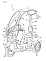
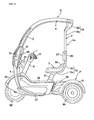
- an electric three-wheeled vehicle V includes: a steering device 1 supporting a single front wheel Wf; a body frame F supporting the steering device 1; a seat 2 for a driver which is supported on the body frame F; a windshield 3 covering the front side of the driver together with the steering device 1; a roof 4 integrally continuous with an upper end portion of the windshield 3, extending rearward and covering the upper side of the driver; a leg shield 5 integrally continuous with a lower end portion of the windshield 3, extending downward and covering the front side of the leg parts of the driver; and a power unit P which, while supporting a pair of left and right rear wheels Wr, Wr, drives them by an electric motor 6.
- the windshield 3, the roof 4 and the leg shield 5 are integrally formed of a single sheet of acrylic resin plate.
- the steering device 1 includes a front fork 10 on which the front wheel Wf is rotatably supported, a steering stem 11 protruding upward beyond the upper end of the front fork 10; and a bar-shaped steering handle 12 attached to the upper end of the steering stem 11.
- the body frame F includes a main frame 14, a seat frame 15, a roof frame 16, and a shield support part 17.
- the main frame 14 includes a head pipe 18 steerably supporting the steering stem 11, a down tube 19 extending rearwardly downward from the head pipe 18, an upwardly opening type battery case 20 integrally connected to the lower end of the down tube 19, and a seat post 21 integrally continuous with a rear portion of the battery case 20 and rising upward.
- a battery 23 for supplying the electric motor 6 with electric power is housed in the battery case 20.
- a pair of left and right footrests 22, 22 protruding to the outer sides than left and right side surfaces of the battery case 20 are firmly attached to the battery case 20.
- the seat frame 15 includes a bottom plate portion 15a integrally connected to the upper end of the seat post 21, and a rising wall portion 15b rising upward from the rear end of the bottom plate portion1 15a; by these portions, the seat 2 having a hip rest 2a is supported.
- the roof frame 16 is composed of two members, namely, a roof post 16a formed of a single rectangular (polygonal) or circular pipe material, connected to the rising wall portion 15b of the seat frame 15 and extending upward, and a roof support member 16b which is composed of an aluminum die casting and connected to the upper end of the roof post 16a.
- the roof support member 16b is composed, in a vertically flattened loop-like general form, of a lower edge portion 24 which has an arcuate shape with both left and right ends thereof warped upward, and an upper edge portion 25 which has an arcuate shape protuberant to the opposite side from the lower edge portion 24 and interconnects the left and right ends of the lower edge portion 24.
- the upper end of the seat post 21 is connected by welding, caulking or the like.
- a rear end portion of the roof 4 is lapped and screwed.
- a stop lamp 26 functioning also as a tail lamp is mounted to the lower edge portion 24.
- a back plate 28 supporting a backrest 27 immediately over the hip rest 2a is attached to the roof post 16a.
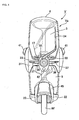
- the shield support part 17 includes: a plurality of stays 29, 29 projectingly provided on a front surface of the head pipe 18; a bracket 30 integrally connected to the front ends of the stays 29, 29 and spreading leftward and rightward; and a cover member 31 which clampingly supports the windshield 3 between itself and the bracket 30.
- a lamp case 33 for holding a head lamp 32 is formed integrally with a central portion of the cover member 31.
- the shield support part 17 supports the head lamp 32 together with the windshield 3.
- a wiper 34 for wiping the front surface of the windshield 3 is mounted to an upper portion of the lamp case 33.
- the leg shield 5 provided integrally continuously with the windshield 3 and covering the front side of the driver's leg parts is connected at its lower end portion to front end portions of the left and right footrests 22, 22.
- the leg shield 5 is provided, in a lower-end central portion thereof, with an arcuate cutout 35 for receiving a front fender 45.
- the cover member 31 is formed with a pair of turn signal lamp mounting recesses 37, 37 which extend long to outer sides from left and right side surfaces of the lamp case 33 and into which front turn signal lamps 36, 36 are mounted.
- the bracket 30 and the cover member 31 are coupled to each other by screws (not shown) penetrating the turn signal lamp mounting recesses 37, 37 and the windshield 3. After the coupling, therefore, the front turn signal lamps 36, 36 mounted into the turn signal lamp mounting recesses 37, 37 hide the screws, thereby giving a better external appearance.
- a horn 42 is mounted to the cover member 31 at a position immediately under the lamp case 33.
- the bracket 30 is integrally formed, at its central portion, with a meter housing 39 in which to house a meter 38 incorporating a speedometer and the like.
- the bracket 30 is integrally formed, at its left and right end portions, with a pair of mirror holders 41, 41 for holding rearview mirrors 40, 40 so that the angles of the rearview mirrors 40, 40 can be adjusted.
- the mirror holders 41, 41 are so formed as to protrude beyond left and right side edges of the windshield 3.
- a handle cover 43 is mounted which covers the steering handle 12, exclusively of left and right grips. At a central portion of the handle cover 43, a small thing container 44 with a lid is formed.
- a body cover 46 for covering the battery case 20 is mounted to the body frame F, in integral continuity with the front fender 45 which covers the upper side and both lateral sides of the front wheel Wf.
- the power unit P is so configured that the left and right rear wheels Wr, Wr are supported on a unit case 49 connected to a rear end portion of the main frame 14 through a pivot joint 47 and a rolling joint 48, and that the electric motor 6 for driving the rear wheels Wr, Wr and a driving device (including a PDU, a charging circuit, etc.) 7 for controlling the energization of the electric motor 6 are housed and held in the unit case 49.
- the driving device 7 is connected to the battery 23 through a flexible high-voltage cable 8.
- the rolling joint 48 includes a joint shaft 50 secured to the front end of the unit case 49 and extending forward, and a joint case 51 fitted and connected to the joint shaft 50 in a relatively rotatable manner.
- the pivot joint 47 includes a joint arm 52 projectingly provided on a rear end surface of the battery case 20, and a pivot shaft 53 which is disposed to be horizontal in the left-right direction and by which a front end portion of the joint case 51 is connected to the joint arm 52 in a vertically swingable fashion.
- a cushion unit 54 is interposed between the battery case 20 and the joint case 51.
- a rear cover 58 for covering the upper surface of the unit case 49 is mounted to the unit case 49.
- Rear fenders 57, 57 covering the upper side of the left and right rear wheels Wr, Wr are provided to be integrally continuous with left and right end portions of the rear cover 58.
- rear turn signal lamps 55, 55 are mounted which are each elongated over the range from an upper surface to a rear surface of the rear fender 57.
- a stop lamp 56 functioning also as a tail lamp is mounted to a central portion of the rear cover 58.
- the portion forwardly of the rolling joint 48 will be referred to as a vehicle main body Va.
- the body frame F of the vehicle main body Va is composed of: the main frame 14 including the head pipe 18, the down tube 19, the battery case 20 and the seat post 21; the seat frame 15 integrally connected to the upper end of the seat post 21; the roof frame 16 rising upward from the rear end of the seat frame 15; and the shield support part 17 forwardly projectingly formed on the head pipe 18.
- the windshield 3 and the roof 4 integrally continuous to each other are supported by the shield support part 17 and the roof frame 16. Therefore, the body frame F constitutes a closed loop-formed rigid structure in cooperation with the windshield 3 and the roof 4. Accordingly, a rigid and lightweight vehicle main body Va can be realized.
- the battery case 20 housing the battery 23 therein and the seat post 21 supporting the seat frame 15 thereon are components of the main frame 14, which greatly contributes to simplification of structure and lightening in weight of the vehicle main body Va.
- the structure in which the footrests 22, 22 protruding to the left and right outer sides of the battery case 20 are firmly attached to the battery case 20 ensures that the footrests 22, 22 can be firmly supported by the highly rigid battery case 20.
- leg shield 5 connected to the footrests 22, 22 at its lower end portions is integrally continuous with the windshield 3, the leg shield 5 is supported by the shield support part 17 and the footrests 22, 22. Consequently, the support structure is made simple and firm.
- the backrest 27 disposed on the upper side of the seat 2 is mounted to the roof frame 16 supporting the roof 4, a support member for exclusive use for supporting the backrest 27 is unnecessitated. This contributes to simplification of structure and lightening in weight of the vehicle main body Va.
- the roof frame 16 is composed of two members, namely, the roof post 16a which is formed of a single pipe material and connected to the seat frame 15 and the die-cast roof support member 16b which is connected to the upper end of the roof post 16a, the roof frame 16 can be simply configured by use of the two members.
- the roof support member 16b is composed, in a loop form, of the lower edge portion 24 which has an arcuate shape with both left and right ends thereof warped upward and the upper edge portion 25 which has an arcuate shape protuberant to the opposite side from the lower edge portion 24 and interconnects the left and right ends of the lower edge portion 25. Therefore, the loop-formed roof support member 16b is high in rigidity.
- the roof 4 joined to the upper edge portion 25 has a centrally raised arcuate shape in cross section, in conformity with the shape of the upper edge portion 16b. Consequently, enhanced rigidity and improved draining properties are secured.
- the shield support part 17 includes the stays 29, 29 projectingly provided on the front surface of the head pipe 18, the bracket 30 integrally connected to the front ends of the stays 29, 29, and the cover member 31 which clampingly supports the windshield 3 between itself and the bracket 30.
- the head lamp 32 and the front turn signal lamps 36, 36 disposed on the left and right sides of the head lamp 32 are mounted to the cover member 31. Therefore, the cover member 31 provided as one of the components of the shield support part 17 serves also as a support member for the head lamp 32 and the front turn signal lamps 36, 36, which can contribute to simplification of structure and improvement in external appearance of the vehicle main body Va.
- the steering handle 12 may be configured to have a looped shape.
- the present invention is applicable also to a roofed electric two-wheeled vehicle.
- the loop-formed roof support member 16b may be injection molded from synthetic resin.
- the electric motor 6 may be a single electric motor of which the driving force is distributed to the left and right rear wheels Wr, Wr, or may be two electric motors by which the left and right rear wheels Wr, Wr are driven individually.
Landscapes
- Engineering & Computer Science (AREA)
- Mechanical Engineering (AREA)
- Automatic Cycles, And Cycles In General (AREA)
- Body Structure For Vehicles (AREA)
- Arrangement Or Mounting Of Propulsion Units For Vehicles (AREA)
Applications Claiming Priority (1)
| Application Number | Priority Date | Filing Date | Title |
|---|---|---|---|
| JP2011211122A JP2013071547A (ja) | 2011-09-27 | 2011-09-27 | 電動車両 |
Publications (2)
| Publication Number | Publication Date |
|---|---|
| EP2574531A1 true EP2574531A1 (fr) | 2013-04-03 |
| EP2574531B1 EP2574531B1 (fr) | 2016-08-10 |
Family
ID=46934465
Family Applications (1)
| Application Number | Title | Priority Date | Filing Date |
|---|---|---|---|
| EP12184806.3A Not-in-force EP2574531B1 (fr) | 2011-09-27 | 2012-09-18 | Véhicule électrique |
Country Status (5)
| Country | Link |
|---|---|
| US (1) | US8678123B2 (fr) |
| EP (1) | EP2574531B1 (fr) |
| JP (1) | JP2013071547A (fr) |
| CN (1) | CN103010362A (fr) |
| ES (1) | ES2587280T3 (fr) |
Cited By (3)
| Publication number | Priority date | Publication date | Assignee | Title |
|---|---|---|---|---|
| WO2020079634A1 (fr) * | 2018-10-18 | 2020-04-23 | Piaggio & C. S.P.A. | Véhicule automobile à selle à deux roues arrière |
| DE102019101009A1 (de) * | 2019-01-16 | 2020-07-16 | Bayerische Motoren Werke Aktiengesellschaft | Einspuriges, motorgetriebenes Zweirad |
| WO2020240273A1 (fr) | 2019-05-24 | 2020-12-03 | Centro De Innovación Para Motociclistas Tech4Riders S.A.S | Motocyclette sûre |
Families Citing this family (22)
| Publication number | Priority date | Publication date | Assignee | Title |
|---|---|---|---|---|
| JP5460545B2 (ja) * | 2010-09-30 | 2014-04-02 | 本田技研工業株式会社 | 電動二輪車のバッテリモジュール取付構造 |
| USD695644S1 (en) * | 2012-08-09 | 2013-12-17 | GM Global Technology Operations LLC | Vehicle body exterior |
| CN104527910A (zh) * | 2015-01-05 | 2015-04-22 | 重庆银钢科技(集团)有限公司 | 一种新型电动车 |
| IT201600101007A1 (it) * | 2016-10-07 | 2018-04-07 | P Gevs S R L | Autoveicolo a trazione elettrica, e relativo metodo di realizzazione |
| CN106828734A (zh) * | 2016-12-31 | 2017-06-13 | 天津市越创科技有限责任公司 | 一种可遮阳避风电动三轮车 |
| CN111971226A (zh) * | 2018-04-26 | 2020-11-20 | 本田技研工业株式会社 | 电动车辆 |
| JP7012834B2 (ja) * | 2018-04-26 | 2022-01-28 | 本田技研工業株式会社 | 電動車両 |
| WO2019207712A1 (fr) * | 2018-04-26 | 2019-10-31 | 本田技研工業株式会社 | Véhicule électrique |
| WO2021039989A1 (fr) | 2019-08-30 | 2021-03-04 | ヤマハ発動機株式会社 | Véhicule inclinable |
| JP7545981B2 (ja) * | 2019-08-30 | 2024-09-05 | ヤマハ発動機株式会社 | リーン車両 |
| USD945319S1 (en) * | 2020-06-30 | 2022-03-08 | Elvy Inc. | Personal electric vehicle |
| USD957289S1 (en) * | 2020-06-30 | 2022-07-12 | Elvy Inc. | Personal electric vehicle |
| CA3183816A1 (fr) | 2020-06-30 | 2022-01-06 | Frank Stronach | Vehicule electrique personnel |
| USD953202S1 (en) * | 2020-08-30 | 2022-05-31 | Adiva (Shanghai) Trading Co., Ltd. | Scooter |
| JP7184862B2 (ja) * | 2020-11-20 | 2022-12-06 | 本田技研工業株式会社 | 鞍乗型車両 |
| JP7317065B2 (ja) * | 2021-03-31 | 2023-07-28 | 本田技研工業株式会社 | 車両 |
| IT202100015341A1 (it) * | 2021-06-11 | 2022-12-11 | Piaggio & C Spa | Veicolo rollante a sella cavalcabile con carenatura all’avantreno non rollante. |
| JP7376558B2 (ja) * | 2021-11-24 | 2023-11-08 | 本田技研工業株式会社 | 鞍乗り型車両 |
| USD1053073S1 (en) * | 2022-01-18 | 2024-12-03 | Yasuka Meye | Trike |
| JP2023131995A (ja) * | 2022-03-10 | 2023-09-22 | 本田技研工業株式会社 | 鞍乗り型車両 |
| CA219219S (en) | 2023-02-14 | 2024-09-24 | Elvy Inc | Electric truck |
| US12071196B1 (en) * | 2023-09-15 | 2024-08-27 | Worldwide Live Shopping Llc | Vehicle and associated components |
Citations (4)
| Publication number | Priority date | Publication date | Assignee | Title |
|---|---|---|---|---|
| FR2534860A1 (fr) * | 1982-10-26 | 1984-04-27 | Honda Motor Co Ltd | Vehicule leger motorise a cabine demontable, comportant un espace de rangement pour les elements demontes de la cabine |
| FR2600611A1 (fr) * | 1986-06-25 | 1987-12-31 | Durand Francois | Coffre avec siege suspendu integre pour trois-roues leger motorise |
| JPS6445080A (en) | 1987-08-12 | 1989-02-17 | Kurieito Kogyo Kk | Electric heater with elastic plate of shape memory alloy |
| WO2008099258A1 (fr) * | 2007-02-15 | 2008-08-21 | Jcp S.R.L. | Structure de protection |
Family Cites Families (19)
| Publication number | Priority date | Publication date | Assignee | Title |
|---|---|---|---|---|
| US4336964A (en) * | 1978-11-24 | 1982-06-29 | American Microcar Incorporated | Lightweight canopy for three-wheeled vehicle with low center of gravity |
| JP3031455B2 (ja) | 1996-07-31 | 2000-04-10 | 本田技研工業株式会社 | 三輪自動車のフロア構造 |
| US5947222A (en) * | 1996-07-31 | 1999-09-07 | Honda Giken Kogyo Kabushiki Kaisha | Three-wheeled automobile |
| JP4045725B2 (ja) * | 2000-07-31 | 2008-02-13 | スズキ株式会社 | 電動車両 |
| JP4584425B2 (ja) * | 2000-08-10 | 2010-11-24 | 本田技研工業株式会社 | 三輪車のパーキングロック装置 |
| JP4391676B2 (ja) * | 2000-09-06 | 2009-12-24 | 本田技研工業株式会社 | 三輪車の車体構造 |
| JP2002079971A (ja) * | 2000-09-06 | 2002-03-19 | Honda Motor Co Ltd | 車両用ウインドシールド |
| US7913784B2 (en) * | 2007-03-30 | 2011-03-29 | Honda Motor Co., Ltd. | Saddle ride, fuel cell powered vehicle |
| JP5149112B2 (ja) * | 2008-02-05 | 2013-02-20 | 本田技研工業株式会社 | 自動二輪車のスクリーン |
| JP5289883B2 (ja) * | 2008-09-30 | 2013-09-11 | 本田技研工業株式会社 | 鞍乗型車両 |
| CN201587484U (zh) * | 2009-05-11 | 2010-09-22 | 潘国陶 | 一种带伸缩顶篷的车 |
| US9162558B2 (en) * | 2009-06-15 | 2015-10-20 | Polaris Industries Inc. | Electric vehicle |
| JP5586204B2 (ja) * | 2009-10-09 | 2014-09-10 | トヨタホーム株式会社 | 建物の屋根構造 |
| CN201872839U (zh) * | 2010-10-08 | 2011-06-22 | 毛卫忠 | 改进的电动车 |
| US8662228B2 (en) * | 2011-01-19 | 2014-03-04 | Green Lite Motors Corporation | Free-to-lean three-wheeled passenger vehicle, power plant controller and body therefor |
| US8997908B2 (en) * | 2011-02-11 | 2015-04-07 | Polaris Industries Inc. | Side-by-side all terrain vehicle |
| JP2012214109A (ja) * | 2011-03-31 | 2012-11-08 | Honda Motor Co Ltd | 電動三輪車 |
| JP5731258B2 (ja) * | 2011-03-31 | 2015-06-10 | 本田技研工業株式会社 | 電動三輪車 |
| JP2012214088A (ja) * | 2011-03-31 | 2012-11-08 | Honda Motor Co Ltd | 電動三輪車 |
-
2011
- 2011-09-27 JP JP2011211122A patent/JP2013071547A/ja not_active Withdrawn
-
2012
- 2012-09-04 CN CN2012103232410A patent/CN103010362A/zh active Pending
- 2012-09-07 US US13/606,498 patent/US8678123B2/en not_active Expired - Fee Related
- 2012-09-18 EP EP12184806.3A patent/EP2574531B1/fr not_active Not-in-force
- 2012-09-18 ES ES12184806.3T patent/ES2587280T3/es active Active
Patent Citations (4)
| Publication number | Priority date | Publication date | Assignee | Title |
|---|---|---|---|---|
| FR2534860A1 (fr) * | 1982-10-26 | 1984-04-27 | Honda Motor Co Ltd | Vehicule leger motorise a cabine demontable, comportant un espace de rangement pour les elements demontes de la cabine |
| FR2600611A1 (fr) * | 1986-06-25 | 1987-12-31 | Durand Francois | Coffre avec siege suspendu integre pour trois-roues leger motorise |
| JPS6445080A (en) | 1987-08-12 | 1989-02-17 | Kurieito Kogyo Kk | Electric heater with elastic plate of shape memory alloy |
| WO2008099258A1 (fr) * | 2007-02-15 | 2008-08-21 | Jcp S.R.L. | Structure de protection |
Cited By (4)
| Publication number | Priority date | Publication date | Assignee | Title |
|---|---|---|---|---|
| WO2020079634A1 (fr) * | 2018-10-18 | 2020-04-23 | Piaggio & C. S.P.A. | Véhicule automobile à selle à deux roues arrière |
| US11794844B2 (en) | 2018-10-18 | 2023-10-24 | Piaggio & C. S.P.A | Riding-saddle motor vehicle with two rear wheels |
| DE102019101009A1 (de) * | 2019-01-16 | 2020-07-16 | Bayerische Motoren Werke Aktiengesellschaft | Einspuriges, motorgetriebenes Zweirad |
| WO2020240273A1 (fr) | 2019-05-24 | 2020-12-03 | Centro De Innovación Para Motociclistas Tech4Riders S.A.S | Motocyclette sûre |
Also Published As
| Publication number | Publication date |
|---|---|
| CN103010362A (zh) | 2013-04-03 |
| JP2013071547A (ja) | 2013-04-22 |
| EP2574531B1 (fr) | 2016-08-10 |
| US8678123B2 (en) | 2014-03-25 |
| US20130075177A1 (en) | 2013-03-28 |
| ES2587280T3 (es) | 2016-10-21 |
Similar Documents
| Publication | Publication Date | Title |
|---|---|---|
| EP2574531B1 (fr) | Véhicule électrique | |
| ES2693949T3 (es) | Estructura de suministro de fuente de alimentación de vehículo | |
| CN105189275A (zh) | 小型摩托车 | |
| EP3061679B1 (fr) | Structure arrière pour véhicule à monture de selle | |
| TW201226252A (en) | Motorcycle | |
| CN112399945B (zh) | 跨骑型电动车辆的车架结构 | |
| CN102120474A (zh) | 跨骑型车辆的方向指示装置 | |
| CN104627294B (zh) | 电动摩托车 | |
| JP2020164073A (ja) | 鞍乗型車両 | |
| JP3695125B2 (ja) | 自動二輪車のバッテリー保持装置 | |
| JPH08207874A (ja) | 電動自転車 | |
| EP2965976B1 (fr) | Dispositif embarqué mobile pour un véhicule de type à selle | |
| JP2009220615A (ja) | 自動二輪車のスクリーン装置 | |
| WO2015152841A1 (fr) | Structure de montage de réservoir de réserve destinée à un scooter | |
| US8506000B2 (en) | Straddle type vehicle | |
| JP5620898B2 (ja) | 電動車両 | |
| CN217477457U (zh) | 跨骑式车辆 | |
| EP2610150B1 (fr) | Véhicule à monture de selle | |
| CN210175050U (zh) | 跨乘型车辆 | |
| JP7610698B2 (ja) | 鞍乗型車両 | |
| US20150191153A1 (en) | Motorcycle Windscreen Wiper System | |
| JP6759268B2 (ja) | 鞍乗り型車両のメーター周辺構造 | |
| CN116601074B (zh) | 跨骑型车辆 | |
| JP5041439B2 (ja) | 自動二輪車 | |
| EP2965975B1 (fr) | Structure de support pour dispositif accessoire embarqué pour véhicule à selle |
Legal Events
| Date | Code | Title | Description |
|---|---|---|---|
| PUAI | Public reference made under article 153(3) epc to a published international application that has entered the european phase |
Free format text: ORIGINAL CODE: 0009012 |
|
| 17P | Request for examination filed |
Effective date: 20120918 |
|
| AK | Designated contracting states |
Kind code of ref document: A1 Designated state(s): AL AT BE BG CH CY CZ DE DK EE ES FI FR GB GR HR HU IE IS IT LI LT LU LV MC MK MT NL NO PL PT RO RS SE SI SK SM TR |
|
| AX | Request for extension of the european patent |
Extension state: BA ME |
|
| 17Q | First examination report despatched |
Effective date: 20141105 |
|
| GRAP | Despatch of communication of intention to grant a patent |
Free format text: ORIGINAL CODE: EPIDOSNIGR1 |
|
| INTG | Intention to grant announced |
Effective date: 20160212 |
|
| GRAS | Grant fee paid |
Free format text: ORIGINAL CODE: EPIDOSNIGR3 |
|
| GRAA | (expected) grant |
Free format text: ORIGINAL CODE: 0009210 |
|
| AK | Designated contracting states |
Kind code of ref document: B1 Designated state(s): AL AT BE BG CH CY CZ DE DK EE ES FI FR GB GR HR HU IE IS IT LI LT LU LV MC MK MT NL NO PL PT RO RS SE SI SK SM TR |
|
| REG | Reference to a national code |
Ref country code: GB Ref legal event code: FG4D |
|
| REG | Reference to a national code |
Ref country code: CH Ref legal event code: EP Ref country code: AT Ref legal event code: REF Ref document number: 818713 Country of ref document: AT Kind code of ref document: T Effective date: 20160815 |
|
| REG | Reference to a national code |
Ref country code: IE Ref legal event code: FG4D |
|
| REG | Reference to a national code |
Ref country code: FR Ref legal event code: PLFP Year of fee payment: 5 |
|
| REG | Reference to a national code |
Ref country code: DE Ref legal event code: R096 Ref document number: 602012021410 Country of ref document: DE |
|
| REG | Reference to a national code |
Ref country code: ES Ref legal event code: FG2A Ref document number: 2587280 Country of ref document: ES Kind code of ref document: T3 Effective date: 20161021 |
|
| REG | Reference to a national code |
Ref country code: LT Ref legal event code: MG4D |
|
| REG | Reference to a national code |
Ref country code: NL Ref legal event code: MP Effective date: 20160810 |
|
| REG | Reference to a national code |
Ref country code: AT Ref legal event code: MK05 Ref document number: 818713 Country of ref document: AT Kind code of ref document: T Effective date: 20160810 |
|
| PG25 | Lapsed in a contracting state [announced via postgrant information from national office to epo] |
Ref country code: HR Free format text: LAPSE BECAUSE OF FAILURE TO SUBMIT A TRANSLATION OF THE DESCRIPTION OR TO PAY THE FEE WITHIN THE PRESCRIBED TIME-LIMIT Effective date: 20160810 Ref country code: RS Free format text: LAPSE BECAUSE OF FAILURE TO SUBMIT A TRANSLATION OF THE DESCRIPTION OR TO PAY THE FEE WITHIN THE PRESCRIBED TIME-LIMIT Effective date: 20160810 Ref country code: FI Free format text: LAPSE BECAUSE OF FAILURE TO SUBMIT A TRANSLATION OF THE DESCRIPTION OR TO PAY THE FEE WITHIN THE PRESCRIBED TIME-LIMIT Effective date: 20160810 Ref country code: NO Free format text: LAPSE BECAUSE OF FAILURE TO SUBMIT A TRANSLATION OF THE DESCRIPTION OR TO PAY THE FEE WITHIN THE PRESCRIBED TIME-LIMIT Effective date: 20161110 Ref country code: LT Free format text: LAPSE BECAUSE OF FAILURE TO SUBMIT A TRANSLATION OF THE DESCRIPTION OR TO PAY THE FEE WITHIN THE PRESCRIBED TIME-LIMIT Effective date: 20160810 Ref country code: NL Free format text: LAPSE BECAUSE OF FAILURE TO SUBMIT A TRANSLATION OF THE DESCRIPTION OR TO PAY THE FEE WITHIN THE PRESCRIBED TIME-LIMIT Effective date: 20160810 Ref country code: IS Free format text: LAPSE BECAUSE OF FAILURE TO SUBMIT A TRANSLATION OF THE DESCRIPTION OR TO PAY THE FEE WITHIN THE PRESCRIBED TIME-LIMIT Effective date: 20161210 |
|
| PG25 | Lapsed in a contracting state [announced via postgrant information from national office to epo] |
Ref country code: BE Free format text: LAPSE BECAUSE OF NON-PAYMENT OF DUE FEES Effective date: 20160930 Ref country code: LV Free format text: LAPSE BECAUSE OF FAILURE TO SUBMIT A TRANSLATION OF THE DESCRIPTION OR TO PAY THE FEE WITHIN THE PRESCRIBED TIME-LIMIT Effective date: 20160810 Ref country code: PL Free format text: LAPSE BECAUSE OF FAILURE TO SUBMIT A TRANSLATION OF THE DESCRIPTION OR TO PAY THE FEE WITHIN THE PRESCRIBED TIME-LIMIT Effective date: 20160810 Ref country code: SE Free format text: LAPSE BECAUSE OF FAILURE TO SUBMIT A TRANSLATION OF THE DESCRIPTION OR TO PAY THE FEE WITHIN THE PRESCRIBED TIME-LIMIT Effective date: 20160810 Ref country code: AT Free format text: LAPSE BECAUSE OF FAILURE TO SUBMIT A TRANSLATION OF THE DESCRIPTION OR TO PAY THE FEE WITHIN THE PRESCRIBED TIME-LIMIT Effective date: 20160810 Ref country code: GR Free format text: LAPSE BECAUSE OF FAILURE TO SUBMIT A TRANSLATION OF THE DESCRIPTION OR TO PAY THE FEE WITHIN THE PRESCRIBED TIME-LIMIT Effective date: 20161111 Ref country code: PT Free format text: LAPSE BECAUSE OF FAILURE TO SUBMIT A TRANSLATION OF THE DESCRIPTION OR TO PAY THE FEE WITHIN THE PRESCRIBED TIME-LIMIT Effective date: 20161212 |
|
| PG25 | Lapsed in a contracting state [announced via postgrant information from national office to epo] |
Ref country code: EE Free format text: LAPSE BECAUSE OF FAILURE TO SUBMIT A TRANSLATION OF THE DESCRIPTION OR TO PAY THE FEE WITHIN THE PRESCRIBED TIME-LIMIT Effective date: 20160810 Ref country code: RO Free format text: LAPSE BECAUSE OF FAILURE TO SUBMIT A TRANSLATION OF THE DESCRIPTION OR TO PAY THE FEE WITHIN THE PRESCRIBED TIME-LIMIT Effective date: 20160810 |
|
| REG | Reference to a national code |
Ref country code: CH Ref legal event code: PL |
|
| REG | Reference to a national code |
Ref country code: DE Ref legal event code: R097 Ref document number: 602012021410 Country of ref document: DE |
|
| PG25 | Lapsed in a contracting state [announced via postgrant information from national office to epo] |
Ref country code: SK Free format text: LAPSE BECAUSE OF FAILURE TO SUBMIT A TRANSLATION OF THE DESCRIPTION OR TO PAY THE FEE WITHIN THE PRESCRIBED TIME-LIMIT Effective date: 20160810 Ref country code: DK Free format text: LAPSE BECAUSE OF FAILURE TO SUBMIT A TRANSLATION OF THE DESCRIPTION OR TO PAY THE FEE WITHIN THE PRESCRIBED TIME-LIMIT Effective date: 20160810 Ref country code: BG Free format text: LAPSE BECAUSE OF FAILURE TO SUBMIT A TRANSLATION OF THE DESCRIPTION OR TO PAY THE FEE WITHIN THE PRESCRIBED TIME-LIMIT Effective date: 20161110 Ref country code: CZ Free format text: LAPSE BECAUSE OF FAILURE TO SUBMIT A TRANSLATION OF THE DESCRIPTION OR TO PAY THE FEE WITHIN THE PRESCRIBED TIME-LIMIT Effective date: 20160810 Ref country code: BE Free format text: LAPSE BECAUSE OF FAILURE TO SUBMIT A TRANSLATION OF THE DESCRIPTION OR TO PAY THE FEE WITHIN THE PRESCRIBED TIME-LIMIT Effective date: 20160810 Ref country code: SM Free format text: LAPSE BECAUSE OF FAILURE TO SUBMIT A TRANSLATION OF THE DESCRIPTION OR TO PAY THE FEE WITHIN THE PRESCRIBED TIME-LIMIT Effective date: 20160810 |
|
| PLBE | No opposition filed within time limit |
Free format text: ORIGINAL CODE: 0009261 |
|
| STAA | Information on the status of an ep patent application or granted ep patent |
Free format text: STATUS: NO OPPOSITION FILED WITHIN TIME LIMIT |
|
| REG | Reference to a national code |
Ref country code: IE Ref legal event code: MM4A |
|
| PG25 | Lapsed in a contracting state [announced via postgrant information from national office to epo] |
Ref country code: MC Free format text: LAPSE BECAUSE OF FAILURE TO SUBMIT A TRANSLATION OF THE DESCRIPTION OR TO PAY THE FEE WITHIN THE PRESCRIBED TIME-LIMIT Effective date: 20160810 |
|
| 26N | No opposition filed |
Effective date: 20170511 |
|
| PG25 | Lapsed in a contracting state [announced via postgrant information from national office to epo] |
Ref country code: CH Free format text: LAPSE BECAUSE OF NON-PAYMENT OF DUE FEES Effective date: 20160930 Ref country code: IE Free format text: LAPSE BECAUSE OF NON-PAYMENT OF DUE FEES Effective date: 20160918 Ref country code: LI Free format text: LAPSE BECAUSE OF NON-PAYMENT OF DUE FEES Effective date: 20160930 |
|
| REG | Reference to a national code |
Ref country code: FR Ref legal event code: PLFP Year of fee payment: 6 |
|
| PG25 | Lapsed in a contracting state [announced via postgrant information from national office to epo] |
Ref country code: SI Free format text: LAPSE BECAUSE OF FAILURE TO SUBMIT A TRANSLATION OF THE DESCRIPTION OR TO PAY THE FEE WITHIN THE PRESCRIBED TIME-LIMIT Effective date: 20160810 Ref country code: LU Free format text: LAPSE BECAUSE OF NON-PAYMENT OF DUE FEES Effective date: 20160918 |
|
| PG25 | Lapsed in a contracting state [announced via postgrant information from national office to epo] |
Ref country code: CY Free format text: LAPSE BECAUSE OF FAILURE TO SUBMIT A TRANSLATION OF THE DESCRIPTION OR TO PAY THE FEE WITHIN THE PRESCRIBED TIME-LIMIT Effective date: 20160810 Ref country code: HU Free format text: LAPSE BECAUSE OF FAILURE TO SUBMIT A TRANSLATION OF THE DESCRIPTION OR TO PAY THE FEE WITHIN THE PRESCRIBED TIME-LIMIT; INVALID AB INITIO Effective date: 20120918 |
|
| PG25 | Lapsed in a contracting state [announced via postgrant information from national office to epo] |
Ref country code: MT Free format text: LAPSE BECAUSE OF NON-PAYMENT OF DUE FEES Effective date: 20160930 Ref country code: MK Free format text: LAPSE BECAUSE OF FAILURE TO SUBMIT A TRANSLATION OF THE DESCRIPTION OR TO PAY THE FEE WITHIN THE PRESCRIBED TIME-LIMIT Effective date: 20160810 Ref country code: TR Free format text: LAPSE BECAUSE OF FAILURE TO SUBMIT A TRANSLATION OF THE DESCRIPTION OR TO PAY THE FEE WITHIN THE PRESCRIBED TIME-LIMIT Effective date: 20160810 |
|
| REG | Reference to a national code |
Ref country code: FR Ref legal event code: PLFP Year of fee payment: 7 |
|
| PG25 | Lapsed in a contracting state [announced via postgrant information from national office to epo] |
Ref country code: AL Free format text: LAPSE BECAUSE OF FAILURE TO SUBMIT A TRANSLATION OF THE DESCRIPTION OR TO PAY THE FEE WITHIN THE PRESCRIBED TIME-LIMIT Effective date: 20160810 |
|
| PGFP | Annual fee paid to national office [announced via postgrant information from national office to epo] |
Ref country code: FR Payment date: 20180813 Year of fee payment: 7 Ref country code: IT Payment date: 20180919 Year of fee payment: 7 |
|
| PGFP | Annual fee paid to national office [announced via postgrant information from national office to epo] |
Ref country code: ES Payment date: 20181001 Year of fee payment: 7 |
|
| REG | Reference to a national code |
Ref country code: DE Ref legal event code: R084 Ref document number: 602012021410 Country of ref document: DE |
|
| PGFP | Annual fee paid to national office [announced via postgrant information from national office to epo] |
Ref country code: GB Payment date: 20190920 Year of fee payment: 8 |
|
| REG | Reference to a national code |
Ref country code: GB Ref legal event code: 746 Effective date: 20191219 |
|
| PG25 | Lapsed in a contracting state [announced via postgrant information from national office to epo] |
Ref country code: IT Free format text: LAPSE BECAUSE OF NON-PAYMENT OF DUE FEES Effective date: 20190918 |
|
| PG25 | Lapsed in a contracting state [announced via postgrant information from national office to epo] |
Ref country code: FR Free format text: LAPSE BECAUSE OF NON-PAYMENT OF DUE FEES Effective date: 20190930 |
|
| REG | Reference to a national code |
Ref country code: ES Ref legal event code: FD2A Effective date: 20210128 |
|
| GBPC | Gb: european patent ceased through non-payment of renewal fee |
Effective date: 20200918 |
|
| PG25 | Lapsed in a contracting state [announced via postgrant information from national office to epo] |
Ref country code: ES Free format text: LAPSE BECAUSE OF NON-PAYMENT OF DUE FEES Effective date: 20190919 |
|
| PG25 | Lapsed in a contracting state [announced via postgrant information from national office to epo] |
Ref country code: GB Free format text: LAPSE BECAUSE OF NON-PAYMENT OF DUE FEES Effective date: 20200918 |
|
| PGFP | Annual fee paid to national office [announced via postgrant information from national office to epo] |
Ref country code: DE Payment date: 20220609 Year of fee payment: 11 |
|
| REG | Reference to a national code |
Ref country code: DE Ref legal event code: R119 Ref document number: 602012021410 Country of ref document: DE |
|
| PG25 | Lapsed in a contracting state [announced via postgrant information from national office to epo] |
Ref country code: DE Free format text: LAPSE BECAUSE OF NON-PAYMENT OF DUE FEES Effective date: 20240403 |