EP2574539A2 - Dérailleur arrière de bicyclette - Google Patents
Dérailleur arrière de bicyclette Download PDFInfo
- Publication number
- EP2574539A2 EP2574539A2 EP12185101A EP12185101A EP2574539A2 EP 2574539 A2 EP2574539 A2 EP 2574539A2 EP 12185101 A EP12185101 A EP 12185101A EP 12185101 A EP12185101 A EP 12185101A EP 2574539 A2 EP2574539 A2 EP 2574539A2
- Authority
- EP
- European Patent Office
- Prior art keywords
- shift stage
- base member
- movable member
- stage positions
- positions
- Prior art date
- Legal status (The legal status is an assumption and is not a legal conclusion. Google has not performed a legal analysis and makes no representation as to the accuracy of the status listed.)
- Granted
Links
Images


Classifications
-
- B—PERFORMING OPERATIONS; TRANSPORTING
- B62—LAND VEHICLES FOR TRAVELLING OTHERWISE THAN ON RAILS
- B62M—RIDER PROPULSION OF WHEELED VEHICLES OR SLEDGES; POWERED PROPULSION OF SLEDGES OR SINGLE-TRACK CYCLES; TRANSMISSIONS SPECIALLY ADAPTED FOR SUCH VEHICLES
- B62M9/00—Transmissions characterised by use of an endless chain, belt, or the like
- B62M9/04—Transmissions characterised by use of an endless chain, belt, or the like of changeable ratio
- B62M9/06—Transmissions characterised by use of an endless chain, belt, or the like of changeable ratio using a single chain, belt, or the like
- B62M9/10—Transmissions characterised by use of an endless chain, belt, or the like of changeable ratio using a single chain, belt, or the like involving different-sized wheels, e.g. rear sprocket chain wheels selectively engaged by the chain, belt, or the like
- B62M9/12—Transmissions characterised by use of an endless chain, belt, or the like of changeable ratio using a single chain, belt, or the like involving different-sized wheels, e.g. rear sprocket chain wheels selectively engaged by the chain, belt, or the like the chain, belt, or the like being laterally shiftable, e.g. using a rear derailleur
- B62M9/121—Rear derailleurs
- B62M9/124—Mechanisms for shifting laterally
-
- B—PERFORMING OPERATIONS; TRANSPORTING
- B62—LAND VEHICLES FOR TRAVELLING OTHERWISE THAN ON RAILS
- B62M—RIDER PROPULSION OF WHEELED VEHICLES OR SLEDGES; POWERED PROPULSION OF SLEDGES OR SINGLE-TRACK CYCLES; TRANSMISSIONS SPECIALLY ADAPTED FOR SUCH VEHICLES
- B62M9/00—Transmissions characterised by use of an endless chain, belt, or the like
- B62M9/04—Transmissions characterised by use of an endless chain, belt, or the like of changeable ratio
- B62M9/06—Transmissions characterised by use of an endless chain, belt, or the like of changeable ratio using a single chain, belt, or the like
- B62M9/10—Transmissions characterised by use of an endless chain, belt, or the like of changeable ratio using a single chain, belt, or the like involving different-sized wheels, e.g. rear sprocket chain wheels selectively engaged by the chain, belt, or the like
- B62M9/12—Transmissions characterised by use of an endless chain, belt, or the like of changeable ratio using a single chain, belt, or the like involving different-sized wheels, e.g. rear sprocket chain wheels selectively engaged by the chain, belt, or the like the chain, belt, or the like being laterally shiftable, e.g. using a rear derailleur
- B62M9/121—Rear derailleurs
- B62M9/124—Mechanisms for shifting laterally
- B62M9/1248—Mechanisms for shifting laterally characterised by the use of biasing means, e.g. springs; Arrangements thereof
Definitions
- This invention generally relates to a motorized rear derailleur. More specifically, the present invention relates to a motorized rear derailleur that generates electrical energy.
- a bicycle rear derailleur is used to selectively move a chain from one of a plurality of sprockets to another for changing speeds of the bicycle.
- a typical rear derailleur has a base member, a movable member supporting a chain guide and a linkage assembly (e.g., a moving mechanism) coupled between the base member and the movable member so that the chain guide moves laterally relative to the base member.
- the base member is typically coupled to the rear end of the bicycle frame by a bolt that forms a B-axle for providing limited rotation with respect to the bicycle frame.
- the chain guide typically includes a pair of guide plates that rotatably support a guide pulley and a tension pulley between the guide plates.
- one end of the control cable is typically connected to one of the links, and another end of the control cable is connected to a shift control device mounted on the bicycle handlebar.
- the operating cable is pulled or released accordingly. Pulling the inner wire moves the chain guide against the biasing force of the spring, while releasing the inner wire causes the chain guide to move due to the biasing force of the spring.
- One aspect presented in this disclosure is to provide a rear derailleur that balances an operation energy used for shifting between each of the shift stage positions.
- a bicycle rear derailleur that basically comprises a base member, a cable operated structure and a movable member.
- the base member includes a bicycle mounting portion.
- the cable operated structure is movably coupled to the base member.
- the movable member is movably supported to the base member by the cable operated structure between a plurality of shift stage positions with respect to the base member.
- the plurality of shift stage positions include a top shift stage position, a low shift stage position and at least three shift stage positions between the top shift stage position and the low shift stage position.
- the cable operated structure is coupled and arranged between the movable member and the base member such that a percentage of a rate of change of operating energy in two adjacent shifting operations between each three consecutive shift stage positions of the movable member relative to the base member excluding the top and low shift stage positions is less than 3.7 %.
- the cable operated structure is further coupled and arranged between the movable member and the base member such that the percentage of the rate of change of the operating energy is less than 3.2 %.
- the cable operated structure includes a first link member and a second link member, the first link member having a first end pivotally mounted to the base member about a first pivot axis and a second end pivotally mounted to the movable member about a second pivot axis, the second link member having a first end pivotally mounted to the base member about a third pivot axis and a second end pivotally mounted to the movable member about a fourth pivot axis.
- the cable operated structure further includes a biasing member interposed between the first and second link members such that the movable member is biased towards one of the top and low shift stage positions.
- the biasing member is a tension spring.
- a chain guide is pivotally attached to the movable member.
- the biasing member biases the movable member in a direction with respect to the base member such that the chain guide is in a position closest to the base member.
- the biasing member being connected to the first and second link members at points lying outside of a quadrilateral having corners corresponding to the first, second, third and fourth pivot axes.
- first and second link members are pivotally mounted to the movable member and the base member such that define a four-bar parallelogram linkage.
- a bicycle rear derailleur comprises a base member including a bicycle mounting portion, a cable operated structure movably coupled to the base member and a movable member movably supported to the base member by the cable operated structure between a plurality of shift stage positions with respect to the base member.
- the plurality of shift stage positions include a top shift stage position, a low shift stage position and at least four shift stage positions between the top shift stage position and the low shift stage position.
- the cable operated structure is coupled and arranged between the movable member and the base member such that a percentage of a rate of change of operating energy in each shifting operations between adjacent shift stage position of the movable member relative to the base member excluding the top and low shift stage positions is less than 30 % .
- the cable operated structure is coupled and arranged between the movable member and the base member such that the percentage of the rate of change of the operating energy is less than 20 %.
- a bicycle rear derailleur comprises a base member including a bicycle mounting portion, a cable operated structure movably coupled to the base member, and a movable member movably supported to the base member by the cable operated structure between a plurality of shift stage positions with respect to the base member.
- the plurality of shift stage positions include a top shift stage position, a low shift stage position and at least four shift stage positions between the top shift stage position and the low shift stage position.
- the cable operated structure is coupled and arranged between the movable member and the base member such that a percentage of a rate of change of operating energy in each shifting operations between each adjacent shift stage position of the movable member relative to the base member including the top and low shift stage positions is less than 60 %.
- the cable operated structure is coupled and arranged between the movable member and the base member such that the percentage of the rate of change of the operating energy is less than 40 %.
- a bicycle rear derailleur comprises a base member including a bicycle mounting portion, a cable operated structure including a first link member and a second link member, a movable member movably supported to the base member by the first and second link members to move between a plurality of shift stage positions with respect to the base member and a biasing member interposed between the first and second link members such that the movable member is biased towards one of a top shift stage position and a low shift stage position.
- the first link member has a first end pivotally mounted to the base member about a first pivot axis and a second end pivotally mounted to the movable member about a second pivot axis.
- the second link member has a first end pivotally mounted to the base member about a third pivot axis and a second end pivotally mounted to the movable member about a fourth pivot axis.
- the biasing member is connected to the first and second link members at points lying outside of a quadrilateral having corners corresponding to the first, second, third and fourth pivot axes.
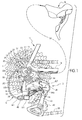
- Figure 1 is a side elevational view of a bicycle gear shift system that includes a rear shifter and a rear derailleur in accordance with one illustrative embodiment
- Figure 2 is a rear elevational view of the rear derailleur in a top shift stage position
- Figure 3 is a rear elevational view of the rear derailleur in a low shift stage position
- Figure 4 is an enlarged side elevational view of the rear derailleur illustrated in the top shift stage position
- Figure 5 is an enlarged side elevational view of the rear derailleur illustrated in the low shift stage position
- Figure 6 is a perspective view of the rear derailleur illustrated in the top shift stage position
- Figure 7 is a perspective view of the rear derailleur illustrated in the top shift stage position, but with a portion broken away to illustrated the spring connection;
- Figure 8 is a perspective view of the rear derailleur illustrated in the low shift stage position.
- a portion of a bicycle 10 is illustrated that includes, among other things, a bicycle rear derailleur 12 in accordance with a first embodiment.
- the rear derailleur 12 is secured to a rear portion of a bicycle frame 14 in a conventional manner.
- the rear derailleur 12 is operated by a rear shifter 16, which is a conventional shift actuating device.
- the rear shifter 16 is a road style shifter that is mounted on a dropdown handlebar (not shown).
- the rear shifter 16 is typically mounted on the bicycle 10 in a location that is convenient for the rider to operate the rear shifter 16 while riding.
- the rear derailleur 12 is operatively connected to the rear shifter 16 by a conventional control cable 18.
- the rear shifter 16 is configured and arranged to operate the rear derailleur 12 between a plurality of shift stage positions such that a chain 20 is moved by the rear derailleur 12 in a lateral direction L between a plurality of rear sprockets 21 to 31.
- rear derailleur are specifically designed for a given number of speeds (i.e., for use with a given number of sprockets).
- a rear cassette has a predetermined axial width with the given number sprockets being spaced apart by a predetermined axial spacing for a given number of speeds.
- the rear derailleur will have a range of movement and will move a predetermined amount to perform a shift from one sprocket to the next adjacent sprocket.
- adjacent refers to sprockets and/or shift stage positions that are immediately next to each other without any intervening sprockets and/or shift stage positions therebetween.
- the rear derailleur 12 is dimensioned to accommodate eleven shift stage positions.
- the rear derailleur 12 can be used with gear shift systems having fewer stages such as five to ten shift stage positions (i.e. the plurality of shift stage positions including a top shift stage position, a low shift stage position and at least three shift stage positions between the top shift stage position and the low shift stage position).
- the cable operated structure e.g., the link members 34 and 36
- the movable member 38 is movable relative to the base member 32 between a plurality of shift stage positions.
- a spring or biasing member 46 is operatively connected between the first and second link members 34 and 36 for biasing the movable member 38 and the chain guide 40 towards the top shift stage position as discussed below.
- control cable 18 is a Bowden cable that basically includes an inner wire 18a that is slidably disposed within an outer casing 18b.
- the inner wire 18a is coupled to one of the first and second link members 34 and 36 (e.g., the inner wire 18a is coupled to the first link member 34 in the illustrated embodiment) to move the movable member 38 and the chain guide 40 laterally relative to the base member 32.
- an operating force or operating energy is applied to the inner wire 18a for performing shifting operations between the shift stage positions.
- the amount of the operating energy for shifting depends on the biasing force of the biasing member 46 and the amount that the inner wire 18a is moved between adjacent shift stage positions.
- the sprocket 21 has an axial thickness of 1.82 millimeters
- the sprocket 22 has an axial thickness of 1.78 millimeters
- each of the sprockets 23 to 31 has an axial thickness of 1.6 millimeters.
- the rear sprockets 21 and 22 are axially spacing apart by 2.0 millimeters
- the rear sprockets 22 and 23 are axially spacing apart by 2.1 millimeters
- the sprockets 23 to 31 are each axially spacing apart by 2.18 millimeters.
- the overall axial dimension of the 11-speed cassette of the illustrated embodiment is 39.54 millimeters.
- the sprocket thickness will typically range from 1.6 to 2.35 millimeters and the axial spacings between the rear sprockets will typically range from 2.35 to 3.95 millimeters.
- the overall axial dimension of a regular 5-speed cassette is typically about 23.2 millimeters with a sprocket thickness of 1.85 millimeters and an axial spacing of 3.5 millimeters.
- the axial thicknesses of the sprockets 21 to 31 and the axial spacings between the sprockets 21 to 31 will vary depending on the particular the drive train design.
- the movable member 38 and the chain guide 40 are moved relative to the base member 32 by an axial distance (e.g., 1.8 millimeters to 3.5 millimeters) in the lateral direction L that corresponds to the axial spacing between the rear sprockets 21 to 31.
- the base member 32 includes a bicycle mounting portion 32a, a link supporting portion 32b and a cable attachment portion 32c with a cable adjustment barrel 48.
- the base member 32 is preferably constructed of a hard rigid material such as a lightweight metal (e.g., an aluminum alloy).
- the bicycle mounting portion 32a has a fixing bolt 50 for securing the rear derailleur 12 to the rear portion (e.g., the derailleur hanger) of the frame 14 of the bicycle 10.
- the fixing bolt 50 is threaded into a threaded hole of the bicycle frame 14.
- the fixing bolt 50 defines a pivot axis A1, which is sometimes called the B-axis of the rear derailleur.
- the pivot axis A1 is parallel to the lateral direction L.
- the bicycle mounting portion 32a preferably includes a biasing arrangement (not shown) that is operatively arranged between the bicycle mounting portion 32a and the bicycle frame 14 in a conventional manner.
- the base member 32 includes a stopper plate 52 that is rotatably mounted to the fixing bolt 50 with a torsion spring (not shown) coaxially disposed on the fixing bolt 50 to biased the base member 32 in a clockwise direction relative to the stopper plate 52 as viewed along the fixing bolt 50 from the side of the bicycle 10 where the rear derailleur 12 is attached.
- a torsion spring is attached to the base member 32, and another end of the torsion spring is attached to the stopper plate 52.
- the bicycle mounting portion 32a is also provided with a top limit screw 56 and a low limit screw 58.
- the top limit screw 56 is threaded into a threaded hole of the bicycle mounting portion 32a such that a tip of the top limit screw 56 contacts the second link member 36 to set the top shift stage position.
- the low limit screw 58 is threaded into a threaded hole of the bicycle mounting portion 32a such that a tip of the low limit screw 58 contacts the first link member 34 to set the low shift stage position.
- the derailleur 12 is configured and arranged with a movement range of the movable member 38 and the chain guide 40 relative to the base member 32 of at least 39.54 millimeters.
- the movement range of the movable member 38 and the chain guide 40 relative to the base member 32 is greater than 39.54 millimeters so that the positions of the movable member 38 and the chain guide 40 in the top and low shift stage positions can be adjusted in the lateral direction L relative to the base member 32.
- the cable adjustment barrel 48 is threaded into a threaded hole of the cable attachment portion 32c such that the relative position of the outer casing 18b with respect to the base member 32 can be adjusted by the user.
- the user can adjust the tension of the inner wire by selectively turning cable adjustment barrel 48.
- the cable adjustment barrel 48 is a conventional structure, and thus, the cable adjustment barrel 48 will not be discussed in further detail herein.
- the first and second link members 34 and 36 are pivotally mounted to the movable member 38 and the base member 32 such that define a four-bar parallelogram linkage having its corners defined by a first pivot axis P1, a second pivot axis P2, a third pivot axis P3 and a fourth pivot axis P4.
- the first and second link members 34 and 36 are preferably constructed of a hard rigid material such as a lightweight metal (e.g., an aluminum alloy).
- the first link member 34 constitutes an outer link of the rear derailleur 12
- the second link member 36 constitutes an inner link of the rear derailleur 12.
- the term “outer link” of a four-bar linkage refers to the link member that is farthest from a vertical longitudinal plane of the bicycle 10 with the rear derailleur 12 in the installed position.
- the term “inner link” of a four-bar linkage refers to the link member that is closest from the vertical longitudinal plane of the bicycle 10 with the rear derailleur 12 in the installed position.
- the first link member 34 is provided with an inner wire attachment structure 34a for attaching the inner wire 18a.
- the inner wire attachment structure 34a includes a threaded hole and a bolt with a washer.
- the inner wire attachment structure 34a is located on the first link member 34 such that the attachment point of the inner wire 18a to the wire attachment structure 34a is located along a line that interconnects the centers of the pivot axes P2 and P4 at least at some point during movement of the movable member 38 between a top shift stage position and a low shift stage position.
- the attachment point of the inner wire 18a to the wire attachment structure 34a is located on the center of the pivot axis P2.
- the attachment point of the inner wire 18a to the wire attachment structure 34a is not located within the four-bar parallelogram linkage defined by the pivot axes P1 to P4 while the movable member 38 is in the top shift stage position.
- a first end of the first link member 34 is pivotally mounted to the base member 32 by a pivot pin 61.
- the first end of the first link member 34 pivots relative to the base member 32 about the first pivot axis P1 that is defined by the pivot pin 61.
- a second end of the first link member 34 is pivotally mounted to the movable member 38 by a pivot pin 62.
- the second end of the first link member 34 pivots relative to the movable member 38 about the second pivot axis P2 that is defined by the pivot pin 62.
- a first end of the second link member 36 is pivotally mounted to the base member 32 by a pivot pin 63.
- the first end of the second link member 36 pivots relative to the base member 32 about the third pivot axis P3 that is defined by the pivot pin 63.
- a second end of the second link member 36 is pivotally mounted to the movable member 38 by a pivot pin 64.
- the second end of the second link member 36 pivots relative to the movable member 38 about the fourth pivot axis P4 that is defined by the pivot pin 64.
- the movable member 38 is preferably constructed of a hard rigid material such as a lightweight metal (e.g., an aluminum alloy).
- the movable member 38 is movably supported to the base member 32 by the first and second link members 34 and 36 (the cable operated structure) to move between a plurality of shift stage positions with respect to the base member 32 as mentioned above.
- the movable member 38 pivotally supports the chain guide 40 for pivotal movement about a pivot axis A2, which is sometimes called the P-axis of the rear derailleur.
- the chain guide 40 basically includes a pair of chain cage plates with the tension pulley 42 and the guide pulley 44 rotatably disposed between the chain cage plates.
- the biasing member 46 is interposed between the first and second link members 34 and 36 (the cable operated structure) such that the movable member 38 is biased towards one of the top shift stage position and the low shift stage position.
- the biasing member 46 is a coil tension spring that biases the movable member 38 towards the top shift stage position.
- the biasing member 46 is connected to the first link member 34 by a first shaft or pin 66 and connected to the second link member 36 by a second shaft or pin 68.
- the pins 66 and 68 are diagonally arranged between the first and second link members 34 and 36 so that the first and second link members 34 and 36 are biased together.
- the biasing member 46 is stretched as the movable member 38 moves from the top shift stage position to the low shift stage position. In the top shift stage position, the biasing member 46 is preloaded (slightly stretched) so that the second link member 36 contacts the tip of the top shift stage adjustment screw 56 as seen in Figure 7 .
- the biasing member 46 is connected to the first and second link members 34 and 36 at points lying outside of a quadrilateral having its corners corresponding to the first, second, third and fourth pivot axes P1 to P4.
- the pins 66 and 68 are disposed between a first straight line which passes through the pivot axes P1 and P3, and a second straight line which is passes through the pivot axes P2 and P4.
- the pins 66 and 68 are not disposed between a third straight line which passes through the pivot axes P1 and P2, and a fourth straight line which is through the pivot axes passes P3 and P4.
- the biasing member 46 biases the movable member 38 in a direction with respect to the base member 32 such that the chain guide 40 is in the top shift stage position (i.e., a position closest to the base member 32).
- the first, second, third and fourth pivot axes P1 to P4 are arranged relative to connection points of the pins 66 and 68 to the first and second link members 34 and 36 to balance the operation energy of shifting between each of the shift stages.
- the balance the operation energy of shifting will be considered with respect to a percentage of a rate of change (difference) of operating energy in performing two adjacent shifting operations between three consecutive shift stage positions excluding shifting to and from the top and low shift stage positions.
- the link members 34 and 36 are coupled and arranged between the movable member 38 and the base member 32 such that the percentage of the rate of change of operating energy in two adjacent shifting operations between each three consecutive shift stage positions of the movable member 38 relative to the base member 32, excluding the top and low shift stage positions, is less than 3.7 %, and more preferably less than 3.2%. Even more preferably, the percentage of the rate of change of operating energy between three consecutive shift stage positions, excluding the top and low shift stage positions, is less than 3% as in the construction of the illustrated embodiment.
- Equation (1) X is the rate of change of the operating energy
- E 1 is an operating energy for shifting between a N shift stage position and a N+1 shift stage position
- E 2 is an operating energy for shifting between a N+1 shift stage position and a N+2 shift stage position.
- the N shift stage position excludes both the top and low shift stage positions and the N+2 shift stage position excludes both the top and low shift stage positions.
- Equation (3) X is the rate of change of the operating energy, E max is a maximum operating energy among operating energies E 1 , E 2 , E 3 , .... , E K , E min is a minimum operating energy among operating energies E 1 , E 2 , E 3 , .... , E K , E N is an operating energy for shifting between a N shift stage position and a N+1 shift stage position, and K is a total number of all shift stages including the top and low shift stage positions.
- the N shift stage position is one of the top and low shift stage positions.
Landscapes
- Engineering & Computer Science (AREA)
- Chemical & Material Sciences (AREA)
- Combustion & Propulsion (AREA)
- Transportation (AREA)
- Mechanical Engineering (AREA)
- Gear-Shifting Mechanisms (AREA)
- Axle Suspensions And Sidecars For Cycles (AREA)
Applications Claiming Priority (1)
| Application Number | Priority Date | Filing Date | Title |
|---|---|---|---|
| US13/246,001 US9150281B2 (en) | 2011-09-27 | 2011-09-27 | Bicycle rear derailleur |
Publications (3)
| Publication Number | Publication Date |
|---|---|
| EP2574539A2 true EP2574539A2 (fr) | 2013-04-03 |
| EP2574539A3 EP2574539A3 (fr) | 2015-04-01 |
| EP2574539B1 EP2574539B1 (fr) | 2024-05-22 |
Family
ID=47010249
Family Applications (1)
| Application Number | Title | Priority Date | Filing Date |
|---|---|---|---|
| EP12185101.8A Active EP2574539B1 (fr) | 2011-09-27 | 2012-09-19 | Dérailleur arrière de bicyclette |
Country Status (4)
| Country | Link |
|---|---|
| US (1) | US9150281B2 (fr) |
| EP (1) | EP2574539B1 (fr) |
| CN (1) | CN103010394B (fr) |
| TW (1) | TWI523792B (fr) |
Cited By (2)
| Publication number | Priority date | Publication date | Assignee | Title |
|---|---|---|---|---|
| CN110857136A (zh) * | 2018-08-22 | 2020-03-03 | Sram德国有限公司 | 具有带传动比的偏心线缆拉动滑轮装置的后轮变速器机构 |
| IT201900013341A1 (it) * | 2019-07-30 | 2021-01-30 | Campagnolo Srl | Sotto-assieme corpo porta-pignoni e pacco pignoni per una ruota posteriore di bicicletta |
Families Citing this family (10)
| Publication number | Priority date | Publication date | Assignee | Title |
|---|---|---|---|---|
| US9623932B2 (en) * | 2014-12-10 | 2017-04-18 | Shimano Inc. | Bicycle derailleur |
| US10065705B2 (en) * | 2015-02-05 | 2018-09-04 | Shimano Inc. | Bicycle derailleur |
| WO2017173151A1 (fr) * | 2016-03-30 | 2017-10-05 | The Cycle Group | Dérailleur pour une bicyclette |
| CN106184597A (zh) * | 2016-08-02 | 2016-12-07 | 兰溪轮峰车料有限公司 | 具有可连续多档位变换的后拨链器 |
| IT201600128989A1 (it) * | 2016-12-20 | 2018-06-20 | Campagnolo Srl | Deragliatore posteriore di bicicletta |
| US10793222B1 (en) | 2017-03-21 | 2020-10-06 | Jonathan K. Harris | Bicycle derailleur having upper and lower alignment assemblies |
| IT201700035716A1 (it) * | 2017-03-31 | 2018-10-01 | Campagnolo Srl | Deragliatore posteriore di bicicletta |
| US10501147B2 (en) * | 2017-08-22 | 2019-12-10 | Shimano Inc. | Bicycle derailleur |
| US11319021B2 (en) * | 2017-08-23 | 2022-05-03 | Shimano Inc. | Bicycle rear derailleur |
| TWI789225B (zh) * | 2022-01-27 | 2023-01-01 | 台灣微轉股份有限公司 | 自行車前撥鏈器 |
Citations (1)
| Publication number | Priority date | Publication date | Assignee | Title |
|---|---|---|---|---|
| US4690663A (en) | 1985-06-17 | 1987-09-01 | Shimano Industrial Company Limited | Rear derailleur for a bicycle |
Family Cites Families (17)
| Publication number | Priority date | Publication date | Assignee | Title |
|---|---|---|---|---|
| FR1319997A (fr) * | 1962-04-20 | 1963-03-01 | Changement de vitesse par déraillement de chaîne, en éléments combinés en matière plastique et en métal pour cycles, tandems, vélomoteurs, motocyclettes ou véhicules similaires | |
| BE672603A (fr) * | 1964-12-14 | 1966-03-16 | ||
| US3535950A (en) * | 1967-11-13 | 1970-10-27 | Shimano Industrial Co | Exposed speed change mechanism for a bicycle |
| US4259873A (en) * | 1978-06-02 | 1981-04-07 | Shimano Industrial Company Limited | Derailleur |
| JP3372616B2 (ja) * | 1993-11-30 | 2003-02-04 | 株式会社シマノ | 自転車用ディレーラ |
| US5533937B1 (en) * | 1995-02-06 | 1998-12-08 | Sram Corp | Bicycle derailleur |
| US5620383A (en) * | 1995-02-06 | 1997-04-15 | Sram Corporation | Bicycle derailleur and actuating system |
| US5860880A (en) * | 1996-11-21 | 1999-01-19 | Shimano, Inc. | Low normal bicycle derailleur which allows lateral movement of the chain guide toward the rear wheel in response to a force directed laterally towards the rear wheel |
| US5897451A (en) * | 1997-04-29 | 1999-04-27 | Shimano, Inc. | Bicycle derailleur having operating forces disposed on opposite sides of a link pivot |
| US6093122A (en) * | 1998-01-09 | 2000-07-25 | Sram Corporation | Hybrid spring for bicycle derailleurs |
| US6290621B1 (en) * | 1999-04-15 | 2001-09-18 | Shimano Inc. | Derailleur for a bicycle |
| JP3746025B2 (ja) * | 2002-07-31 | 2006-02-15 | 株式会社シマノ | 自転車用リアディレーラ |
| US6997835B2 (en) * | 2002-11-26 | 2006-02-14 | Shimano, Inc. | Electrically operated derailleur with power storing mechanism |
| US7290458B2 (en) * | 2004-02-24 | 2007-11-06 | Shimano, Inc. | Bicycle derailleur with a motor disposed within a linkage mechanism |
| US7467567B2 (en) * | 2004-02-24 | 2008-12-23 | Shimano, Inc. | Gear reduction apparatus for a bicycle component |
| US7527571B2 (en) * | 2004-12-20 | 2009-05-05 | Shimano Inc. | Rear derailleur for bicycle |
| US8016705B2 (en) * | 2007-04-19 | 2011-09-13 | Shimano Inc. | Bicycle component positioning device |
-
2011
- 2011-09-27 US US13/246,001 patent/US9150281B2/en active Active
-
2012
- 2012-03-20 TW TW101109573A patent/TWI523792B/zh active
- 2012-05-30 CN CN201210172593.0A patent/CN103010394B/zh active Active
- 2012-09-19 EP EP12185101.8A patent/EP2574539B1/fr active Active
Patent Citations (2)
| Publication number | Priority date | Publication date | Assignee | Title |
|---|---|---|---|---|
| US4690663A (en) | 1985-06-17 | 1987-09-01 | Shimano Industrial Company Limited | Rear derailleur for a bicycle |
| US4690663B1 (en) | 1985-06-17 | 1997-05-13 | Shimano Industrial Co | Rear derailleur for a bicycle |
Cited By (5)
| Publication number | Priority date | Publication date | Assignee | Title |
|---|---|---|---|---|
| CN110857136A (zh) * | 2018-08-22 | 2020-03-03 | Sram德国有限公司 | 具有带传动比的偏心线缆拉动滑轮装置的后轮变速器机构 |
| CN110857136B (zh) * | 2018-08-22 | 2022-07-22 | Sram德国有限公司 | 具有带传动比的偏心线缆拉动滑轮装置的后轮变速器机构 |
| IT201900013341A1 (it) * | 2019-07-30 | 2021-01-30 | Campagnolo Srl | Sotto-assieme corpo porta-pignoni e pacco pignoni per una ruota posteriore di bicicletta |
| EP3771629A1 (fr) * | 2019-07-30 | 2021-02-03 | Campagnolo S.r.l. | Sous-ensemble de support d'un ensemble de pignons et cassette de pignons pour roue arrière de bicyclette |
| US11584477B2 (en) | 2019-07-30 | 2023-02-21 | Campagnolo S.R.L. | Sub-assembly sprocket-carrying body and cogset for a bicycle rear wheel |
Also Published As
| Publication number | Publication date |
|---|---|
| CN103010394A (zh) | 2013-04-03 |
| TWI523792B (zh) | 2016-03-01 |
| TW201313543A (zh) | 2013-04-01 |
| US20130079184A1 (en) | 2013-03-28 |
| CN103010394B (zh) | 2014-12-24 |
| US9150281B2 (en) | 2015-10-06 |
| EP2574539B1 (fr) | 2024-05-22 |
| EP2574539A3 (fr) | 2015-04-01 |
Similar Documents
| Publication | Publication Date | Title |
|---|---|---|
| US9150281B2 (en) | Bicycle rear derailleur | |
| US7014584B2 (en) | Top pull type front derailleur | |
| US10315728B2 (en) | Bicycle rear derailleur with a motion resisting structure | |
| US9227696B2 (en) | Bicycle derailleur | |
| EP2524862B1 (fr) | Dérailleur avant d'une bicyclette | |
| EP1902937B1 (fr) | Dérailleur arrière pour bicyclette | |
| US20160068225A1 (en) | Bicycle front derailleur | |
| EP2653372B1 (fr) | Guide de chaîne de bicyclette | |
| US8303443B2 (en) | Six link front derailleur | |
| EP2210806B1 (fr) | Dérailleur de bicyclette | |
| EP2030889B1 (fr) | Dérailleur arrière de bicyclette | |
| EP1902936A1 (fr) | Dérailleur arrière pour bicyclette | |
| US20090247334A1 (en) | Bicycle derailleur | |
| EP2572972B1 (fr) | Dérailleur avant d'une bicyclette | |
| EP1935774A1 (fr) | Dérailleur arrière de bicyclette | |
| US9616970B2 (en) | Bicycle derailleur | |
| US20130085026A1 (en) | Bicycle front derailleur with a variable actuation ratio | |
| EP1688346A2 (fr) | Dérailleur pour bicyclette avec structure de limitation de mouvement | |
| EP1790563B1 (fr) | Dérailleur avant avec mécanisme de réglage de l'angle pour une bicyclette |
Legal Events
| Date | Code | Title | Description |
|---|---|---|---|
| PUAI | Public reference made under article 153(3) epc to a published international application that has entered the european phase |
Free format text: ORIGINAL CODE: 0009012 |
|
| AK | Designated contracting states |
Kind code of ref document: A2 Designated state(s): AL AT BE BG CH CY CZ DE DK EE ES FI FR GB GR HR HU IE IS IT LI LT LU LV MC MK MT NL NO PL PT RO RS SE SI SK SM TR |
|
| AX | Request for extension of the european patent |
Extension state: BA ME |
|
| PUAL | Search report despatched |
Free format text: ORIGINAL CODE: 0009013 |
|
| AK | Designated contracting states |
Kind code of ref document: A3 Designated state(s): AL AT BE BG CH CY CZ DE DK EE ES FI FR GB GR HR HU IE IS IT LI LT LU LV MC MK MT NL NO PL PT RO RS SE SI SK SM TR |
|
| AX | Request for extension of the european patent |
Extension state: BA ME |
|
| RIC1 | Information provided on ipc code assigned before grant |
Ipc: B62M 9/124 20100101AFI20150220BHEP |
|
| 17P | Request for examination filed |
Effective date: 20150811 |
|
| RBV | Designated contracting states (corrected) |
Designated state(s): AL AT BE BG CH CY CZ DE DK EE ES FI FR GB GR HR HU IE IS IT LI LT LU LV MC MK MT NL NO PL PT RO RS SE SI SK SM TR |
|
| 17Q | First examination report despatched |
Effective date: 20151221 |
|
| STAA | Information on the status of an ep patent application or granted ep patent |
Free format text: STATUS: EXAMINATION IS IN PROGRESS |
|
| GRAP | Despatch of communication of intention to grant a patent |
Free format text: ORIGINAL CODE: EPIDOSNIGR1 |
|
| STAA | Information on the status of an ep patent application or granted ep patent |
Free format text: STATUS: GRANT OF PATENT IS INTENDED |
|
| INTG | Intention to grant announced |
Effective date: 20231218 |
|
| GRAS | Grant fee paid |
Free format text: ORIGINAL CODE: EPIDOSNIGR3 |
|
| GRAA | (expected) grant |
Free format text: ORIGINAL CODE: 0009210 |
|
| STAA | Information on the status of an ep patent application or granted ep patent |
Free format text: STATUS: THE PATENT HAS BEEN GRANTED |
|
| AK | Designated contracting states |
Kind code of ref document: B1 Designated state(s): AL AT BE BG CH CY CZ DE DK EE ES FI FR GB GR HR HU IE IS IT LI LT LU LV MC MK MT NL NO PL PT RO RS SE SI SK SM TR |
|
| REG | Reference to a national code |
Ref country code: GB Ref legal event code: FG4D |
|
| REG | Reference to a national code |
Ref country code: CH Ref legal event code: EP |
|
| REG | Reference to a national code |
Ref country code: DE Ref legal event code: R096 Ref document number: 602012080803 Country of ref document: DE |
|
| REG | Reference to a national code |
Ref country code: IE Ref legal event code: FG4D |
|
| P01 | Opt-out of the competence of the unified patent court (upc) registered |
Free format text: CASE NUMBER: APP_36124/2024 Effective date: 20240618 |
|
| REG | Reference to a national code |
Ref country code: LT Ref legal event code: MG9D |
|
| REG | Reference to a national code |
Ref country code: NL Ref legal event code: MP Effective date: 20240522 |
|
| PG25 | Lapsed in a contracting state [announced via postgrant information from national office to epo] |
Ref country code: IS Free format text: LAPSE BECAUSE OF FAILURE TO SUBMIT A TRANSLATION OF THE DESCRIPTION OR TO PAY THE FEE WITHIN THE PRESCRIBED TIME-LIMIT Effective date: 20240922 |
|
| PG25 | Lapsed in a contracting state [announced via postgrant information from national office to epo] |
Ref country code: BG Free format text: LAPSE BECAUSE OF FAILURE TO SUBMIT A TRANSLATION OF THE DESCRIPTION OR TO PAY THE FEE WITHIN THE PRESCRIBED TIME-LIMIT Effective date: 20240522 |
|
| PG25 | Lapsed in a contracting state [announced via postgrant information from national office to epo] |
Ref country code: HR Free format text: LAPSE BECAUSE OF FAILURE TO SUBMIT A TRANSLATION OF THE DESCRIPTION OR TO PAY THE FEE WITHIN THE PRESCRIBED TIME-LIMIT Effective date: 20240522 Ref country code: FI Free format text: LAPSE BECAUSE OF FAILURE TO SUBMIT A TRANSLATION OF THE DESCRIPTION OR TO PAY THE FEE WITHIN THE PRESCRIBED TIME-LIMIT Effective date: 20240522 |
|
| PG25 | Lapsed in a contracting state [announced via postgrant information from national office to epo] |
Ref country code: GR Free format text: LAPSE BECAUSE OF FAILURE TO SUBMIT A TRANSLATION OF THE DESCRIPTION OR TO PAY THE FEE WITHIN THE PRESCRIBED TIME-LIMIT Effective date: 20240823 |
|
| PG25 | Lapsed in a contracting state [announced via postgrant information from national office to epo] |
Ref country code: PT Free format text: LAPSE BECAUSE OF FAILURE TO SUBMIT A TRANSLATION OF THE DESCRIPTION OR TO PAY THE FEE WITHIN THE PRESCRIBED TIME-LIMIT Effective date: 20240923 |
|
| REG | Reference to a national code |
Ref country code: AT Ref legal event code: MK05 Ref document number: 1688572 Country of ref document: AT Kind code of ref document: T Effective date: 20240522 |
|
| PG25 | Lapsed in a contracting state [announced via postgrant information from national office to epo] |
Ref country code: NL Free format text: LAPSE BECAUSE OF FAILURE TO SUBMIT A TRANSLATION OF THE DESCRIPTION OR TO PAY THE FEE WITHIN THE PRESCRIBED TIME-LIMIT Effective date: 20240522 |
|
| PG25 | Lapsed in a contracting state [announced via postgrant information from national office to epo] |
Ref country code: ES Free format text: LAPSE BECAUSE OF FAILURE TO SUBMIT A TRANSLATION OF THE DESCRIPTION OR TO PAY THE FEE WITHIN THE PRESCRIBED TIME-LIMIT Effective date: 20240522 |
|
| PG25 | Lapsed in a contracting state [announced via postgrant information from national office to epo] |
Ref country code: AT Free format text: LAPSE BECAUSE OF FAILURE TO SUBMIT A TRANSLATION OF THE DESCRIPTION OR TO PAY THE FEE WITHIN THE PRESCRIBED TIME-LIMIT Effective date: 20240522 |
|
| PG25 | Lapsed in a contracting state [announced via postgrant information from national office to epo] |
Ref country code: PL Free format text: LAPSE BECAUSE OF FAILURE TO SUBMIT A TRANSLATION OF THE DESCRIPTION OR TO PAY THE FEE WITHIN THE PRESCRIBED TIME-LIMIT Effective date: 20240522 |
|
| PG25 | Lapsed in a contracting state [announced via postgrant information from national office to epo] |
Ref country code: LV Free format text: LAPSE BECAUSE OF FAILURE TO SUBMIT A TRANSLATION OF THE DESCRIPTION OR TO PAY THE FEE WITHIN THE PRESCRIBED TIME-LIMIT Effective date: 20240522 |
|
| PG25 | Lapsed in a contracting state [announced via postgrant information from national office to epo] |
Ref country code: PT Free format text: LAPSE BECAUSE OF FAILURE TO SUBMIT A TRANSLATION OF THE DESCRIPTION OR TO PAY THE FEE WITHIN THE PRESCRIBED TIME-LIMIT Effective date: 20240923 Ref country code: PL Free format text: LAPSE BECAUSE OF FAILURE TO SUBMIT A TRANSLATION OF THE DESCRIPTION OR TO PAY THE FEE WITHIN THE PRESCRIBED TIME-LIMIT Effective date: 20240522 Ref country code: NO Free format text: LAPSE BECAUSE OF FAILURE TO SUBMIT A TRANSLATION OF THE DESCRIPTION OR TO PAY THE FEE WITHIN THE PRESCRIBED TIME-LIMIT Effective date: 20240822 Ref country code: NL Free format text: LAPSE BECAUSE OF FAILURE TO SUBMIT A TRANSLATION OF THE DESCRIPTION OR TO PAY THE FEE WITHIN THE PRESCRIBED TIME-LIMIT Effective date: 20240522 Ref country code: LV Free format text: LAPSE BECAUSE OF FAILURE TO SUBMIT A TRANSLATION OF THE DESCRIPTION OR TO PAY THE FEE WITHIN THE PRESCRIBED TIME-LIMIT Effective date: 20240522 Ref country code: IS Free format text: LAPSE BECAUSE OF FAILURE TO SUBMIT A TRANSLATION OF THE DESCRIPTION OR TO PAY THE FEE WITHIN THE PRESCRIBED TIME-LIMIT Effective date: 20240922 Ref country code: HR Free format text: LAPSE BECAUSE OF FAILURE TO SUBMIT A TRANSLATION OF THE DESCRIPTION OR TO PAY THE FEE WITHIN THE PRESCRIBED TIME-LIMIT Effective date: 20240522 Ref country code: GR Free format text: LAPSE BECAUSE OF FAILURE TO SUBMIT A TRANSLATION OF THE DESCRIPTION OR TO PAY THE FEE WITHIN THE PRESCRIBED TIME-LIMIT Effective date: 20240823 Ref country code: FI Free format text: LAPSE BECAUSE OF FAILURE TO SUBMIT A TRANSLATION OF THE DESCRIPTION OR TO PAY THE FEE WITHIN THE PRESCRIBED TIME-LIMIT Effective date: 20240522 Ref country code: ES Free format text: LAPSE BECAUSE OF FAILURE TO SUBMIT A TRANSLATION OF THE DESCRIPTION OR TO PAY THE FEE WITHIN THE PRESCRIBED TIME-LIMIT Effective date: 20240522 Ref country code: BG Free format text: LAPSE BECAUSE OF FAILURE TO SUBMIT A TRANSLATION OF THE DESCRIPTION OR TO PAY THE FEE WITHIN THE PRESCRIBED TIME-LIMIT Effective date: 20240522 Ref country code: AT Free format text: LAPSE BECAUSE OF FAILURE TO SUBMIT A TRANSLATION OF THE DESCRIPTION OR TO PAY THE FEE WITHIN THE PRESCRIBED TIME-LIMIT Effective date: 20240522 Ref country code: RS Free format text: LAPSE BECAUSE OF FAILURE TO SUBMIT A TRANSLATION OF THE DESCRIPTION OR TO PAY THE FEE WITHIN THE PRESCRIBED TIME-LIMIT Effective date: 20240822 |
|
| PG25 | Lapsed in a contracting state [announced via postgrant information from national office to epo] |
Ref country code: DK Free format text: LAPSE BECAUSE OF FAILURE TO SUBMIT A TRANSLATION OF THE DESCRIPTION OR TO PAY THE FEE WITHIN THE PRESCRIBED TIME-LIMIT Effective date: 20240522 |
|
| PG25 | Lapsed in a contracting state [announced via postgrant information from national office to epo] |
Ref country code: EE Free format text: LAPSE BECAUSE OF FAILURE TO SUBMIT A TRANSLATION OF THE DESCRIPTION OR TO PAY THE FEE WITHIN THE PRESCRIBED TIME-LIMIT Effective date: 20240522 |
|
| PG25 | Lapsed in a contracting state [announced via postgrant information from national office to epo] |
Ref country code: CZ Free format text: LAPSE BECAUSE OF FAILURE TO SUBMIT A TRANSLATION OF THE DESCRIPTION OR TO PAY THE FEE WITHIN THE PRESCRIBED TIME-LIMIT Effective date: 20240522 |
|
| PG25 | Lapsed in a contracting state [announced via postgrant information from national office to epo] |
Ref country code: RO Free format text: LAPSE BECAUSE OF FAILURE TO SUBMIT A TRANSLATION OF THE DESCRIPTION OR TO PAY THE FEE WITHIN THE PRESCRIBED TIME-LIMIT Effective date: 20240522 Ref country code: SK Free format text: LAPSE BECAUSE OF FAILURE TO SUBMIT A TRANSLATION OF THE DESCRIPTION OR TO PAY THE FEE WITHIN THE PRESCRIBED TIME-LIMIT Effective date: 20240522 |
|
| PG25 | Lapsed in a contracting state [announced via postgrant information from national office to epo] |
Ref country code: SM Free format text: LAPSE BECAUSE OF FAILURE TO SUBMIT A TRANSLATION OF THE DESCRIPTION OR TO PAY THE FEE WITHIN THE PRESCRIBED TIME-LIMIT Effective date: 20240522 |
|
| PG25 | Lapsed in a contracting state [announced via postgrant information from national office to epo] |
Ref country code: SM Free format text: LAPSE BECAUSE OF FAILURE TO SUBMIT A TRANSLATION OF THE DESCRIPTION OR TO PAY THE FEE WITHIN THE PRESCRIBED TIME-LIMIT Effective date: 20240522 Ref country code: SK Free format text: LAPSE BECAUSE OF FAILURE TO SUBMIT A TRANSLATION OF THE DESCRIPTION OR TO PAY THE FEE WITHIN THE PRESCRIBED TIME-LIMIT Effective date: 20240522 Ref country code: RO Free format text: LAPSE BECAUSE OF FAILURE TO SUBMIT A TRANSLATION OF THE DESCRIPTION OR TO PAY THE FEE WITHIN THE PRESCRIBED TIME-LIMIT Effective date: 20240522 Ref country code: EE Free format text: LAPSE BECAUSE OF FAILURE TO SUBMIT A TRANSLATION OF THE DESCRIPTION OR TO PAY THE FEE WITHIN THE PRESCRIBED TIME-LIMIT Effective date: 20240522 Ref country code: DK Free format text: LAPSE BECAUSE OF FAILURE TO SUBMIT A TRANSLATION OF THE DESCRIPTION OR TO PAY THE FEE WITHIN THE PRESCRIBED TIME-LIMIT Effective date: 20240522 Ref country code: CZ Free format text: LAPSE BECAUSE OF FAILURE TO SUBMIT A TRANSLATION OF THE DESCRIPTION OR TO PAY THE FEE WITHIN THE PRESCRIBED TIME-LIMIT Effective date: 20240522 |
|
| PG25 | Lapsed in a contracting state [announced via postgrant information from national office to epo] |
Ref country code: IT Free format text: LAPSE BECAUSE OF FAILURE TO SUBMIT A TRANSLATION OF THE DESCRIPTION OR TO PAY THE FEE WITHIN THE PRESCRIBED TIME-LIMIT Effective date: 20240522 |
|
| REG | Reference to a national code |
Ref country code: DE Ref legal event code: R097 Ref document number: 602012080803 Country of ref document: DE |
|
| PLBE | No opposition filed within time limit |
Free format text: ORIGINAL CODE: 0009261 |
|
| STAA | Information on the status of an ep patent application or granted ep patent |
Free format text: STATUS: NO OPPOSITION FILED WITHIN TIME LIMIT |
|
| PG25 | Lapsed in a contracting state [announced via postgrant information from national office to epo] |
Ref country code: MC Free format text: LAPSE BECAUSE OF FAILURE TO SUBMIT A TRANSLATION OF THE DESCRIPTION OR TO PAY THE FEE WITHIN THE PRESCRIBED TIME-LIMIT Effective date: 20240522 Ref country code: SI Free format text: LAPSE BECAUSE OF FAILURE TO SUBMIT A TRANSLATION OF THE DESCRIPTION OR TO PAY THE FEE WITHIN THE PRESCRIBED TIME-LIMIT Effective date: 20240522 |
|
| 26N | No opposition filed |
Effective date: 20250225 |
|
| REG | Reference to a national code |
Ref country code: CH Ref legal event code: PL |
|
| PG25 | Lapsed in a contracting state [announced via postgrant information from national office to epo] |
Ref country code: LU Free format text: LAPSE BECAUSE OF NON-PAYMENT OF DUE FEES Effective date: 20240919 |
|
| GBPC | Gb: european patent ceased through non-payment of renewal fee |
Effective date: 20240919 |
|
| PG25 | Lapsed in a contracting state [announced via postgrant information from national office to epo] |
Ref country code: GB Free format text: LAPSE BECAUSE OF NON-PAYMENT OF DUE FEES Effective date: 20240919 |
|
| REG | Reference to a national code |
Ref country code: BE Ref legal event code: MM Effective date: 20240930 |
|
| PG25 | Lapsed in a contracting state [announced via postgrant information from national office to epo] |
Ref country code: BE Free format text: LAPSE BECAUSE OF NON-PAYMENT OF DUE FEES Effective date: 20240930 |
|
| PG25 | Lapsed in a contracting state [announced via postgrant information from national office to epo] |
Ref country code: FR Free format text: LAPSE BECAUSE OF NON-PAYMENT OF DUE FEES Effective date: 20240930 |
|
| PG25 | Lapsed in a contracting state [announced via postgrant information from national office to epo] |
Ref country code: CH Free format text: LAPSE BECAUSE OF NON-PAYMENT OF DUE FEES Effective date: 20240930 |
|
| PG25 | Lapsed in a contracting state [announced via postgrant information from national office to epo] |
Ref country code: IE Free format text: LAPSE BECAUSE OF NON-PAYMENT OF DUE FEES Effective date: 20240919 |
|
| PG25 | Lapsed in a contracting state [announced via postgrant information from national office to epo] |
Ref country code: SE Free format text: LAPSE BECAUSE OF FAILURE TO SUBMIT A TRANSLATION OF THE DESCRIPTION OR TO PAY THE FEE WITHIN THE PRESCRIBED TIME-LIMIT Effective date: 20240522 |
|
| PGFP | Annual fee paid to national office [announced via postgrant information from national office to epo] |
Ref country code: DE Payment date: 20250730 Year of fee payment: 14 |
|
| PG25 | Lapsed in a contracting state [announced via postgrant information from national office to epo] |
Ref country code: CY Free format text: LAPSE BECAUSE OF FAILURE TO SUBMIT A TRANSLATION OF THE DESCRIPTION OR TO PAY THE FEE WITHIN THE PRESCRIBED TIME-LIMIT; INVALID AB INITIO Effective date: 20120919 |
|
| PG25 | Lapsed in a contracting state [announced via postgrant information from national office to epo] |
Ref country code: HU Free format text: LAPSE BECAUSE OF FAILURE TO SUBMIT A TRANSLATION OF THE DESCRIPTION OR TO PAY THE FEE WITHIN THE PRESCRIBED TIME-LIMIT; INVALID AB INITIO Effective date: 20120919 |