EP2574551A2 - Cockpit eines Luftfahrzeugs mit einem Notsitz - Google Patents
Cockpit eines Luftfahrzeugs mit einem Notsitz Download PDFInfo
- Publication number
- EP2574551A2 EP2574551A2 EP12186328A EP12186328A EP2574551A2 EP 2574551 A2 EP2574551 A2 EP 2574551A2 EP 12186328 A EP12186328 A EP 12186328A EP 12186328 A EP12186328 A EP 12186328A EP 2574551 A2 EP2574551 A2 EP 2574551A2
- Authority
- EP
- European Patent Office
- Prior art keywords
- seat
- cockpit
- jump
- aircraft
- corridor
- Prior art date
- Legal status (The legal status is an assumption and is not a legal conclusion. Google has not performed a legal analysis and makes no representation as to the accuracy of the status listed.)
- Granted
Links
Images



Classifications
-
- B—PERFORMING OPERATIONS; TRANSPORTING
- B64—AIRCRAFT; AVIATION; COSMONAUTICS
- B64D—EQUIPMENT FOR FITTING IN OR TO AIRCRAFT; FLIGHT SUITS; PARACHUTES; ARRANGEMENT OR MOUNTING OF POWER PLANTS OR PROPULSION TRANSMISSIONS IN AIRCRAFT
- B64D11/00—Passenger or crew accommodation; Flight-deck installations not otherwise provided for
- B64D11/06—Arrangements of seats, or adaptations or details specially adapted for aircraft seats
- B64D11/0689—Arrangements of seats, or adaptations or details specially adapted for aircraft seats specially adapted for pilots
-
- B—PERFORMING OPERATIONS; TRANSPORTING
- B64—AIRCRAFT; AVIATION; COSMONAUTICS
- B64D—EQUIPMENT FOR FITTING IN OR TO AIRCRAFT; FLIGHT SUITS; PARACHUTES; ARRANGEMENT OR MOUNTING OF POWER PLANTS OR PROPULSION TRANSMISSIONS IN AIRCRAFT
- B64D45/00—Aircraft indicators or protectors not otherwise provided for
- B64D45/0015—Devices specially adapted for the protection against criminal attack, e.g. anti-hijacking systems
- B64D45/0021—Devices specially adapted for the protection against criminal attack, e.g. anti-hijacking systems means for restricting access to flight deck
- B64D45/0028—Devices specially adapted for the protection against criminal attack, e.g. anti-hijacking systems means for restricting access to flight deck doors or door arrangements specially adapted to restrict unauthorized access
-
- B—PERFORMING OPERATIONS; TRANSPORTING
- B64—AIRCRAFT; AVIATION; COSMONAUTICS
- B64C—AEROPLANES; HELICOPTERS
- B64C1/00—Fuselages; Constructional features common to fuselages, wings, stabilising surfaces or the like
- B64C1/14—Windows; Doors; Hatch covers or access panels; Surrounding frame structures; Canopies; Windscreens accessories therefor, e.g. pressure sensors, water deflectors, hinges, seals, handles, latches, windscreen wipers
- B64C1/1407—Doors; surrounding frames
- B64C1/1469—Doors between cockpit and cabin
-
- B—PERFORMING OPERATIONS; TRANSPORTING
- B64—AIRCRAFT; AVIATION; COSMONAUTICS
- B64D—EQUIPMENT FOR FITTING IN OR TO AIRCRAFT; FLIGHT SUITS; PARACHUTES; ARRANGEMENT OR MOUNTING OF POWER PLANTS OR PROPULSION TRANSMISSIONS IN AIRCRAFT
- B64D11/00—Passenger or crew accommodation; Flight-deck installations not otherwise provided for
- B64D11/06—Arrangements of seats, or adaptations or details specially adapted for aircraft seats
-
- B—PERFORMING OPERATIONS; TRANSPORTING
- B64—AIRCRAFT; AVIATION; COSMONAUTICS
- B64D—EQUIPMENT FOR FITTING IN OR TO AIRCRAFT; FLIGHT SUITS; PARACHUTES; ARRANGEMENT OR MOUNTING OF POWER PLANTS OR PROPULSION TRANSMISSIONS IN AIRCRAFT
- B64D11/00—Passenger or crew accommodation; Flight-deck installations not otherwise provided for
- B64D11/06—Arrangements of seats, or adaptations or details specially adapted for aircraft seats
- B64D11/0606—Arrangements of seats, or adaptations or details specially adapted for aircraft seats with privacy shells, screens, separators or the like
-
- B—PERFORMING OPERATIONS; TRANSPORTING
- B64—AIRCRAFT; AVIATION; COSMONAUTICS
- B64D—EQUIPMENT FOR FITTING IN OR TO AIRCRAFT; FLIGHT SUITS; PARACHUTES; ARRANGEMENT OR MOUNTING OF POWER PLANTS OR PROPULSION TRANSMISSIONS IN AIRCRAFT
- B64D11/00—Passenger or crew accommodation; Flight-deck installations not otherwise provided for
- B64D11/06—Arrangements of seats, or adaptations or details specially adapted for aircraft seats
- B64D11/0639—Arrangements of seats, or adaptations or details specially adapted for aircraft seats with features for adjustment or converting of seats
- B64D11/064—Adjustable inclination or position of seats
-
- B—PERFORMING OPERATIONS; TRANSPORTING
- B64—AIRCRAFT; AVIATION; COSMONAUTICS
- B64D—EQUIPMENT FOR FITTING IN OR TO AIRCRAFT; FLIGHT SUITS; PARACHUTES; ARRANGEMENT OR MOUNTING OF POWER PLANTS OR PROPULSION TRANSMISSIONS IN AIRCRAFT
- B64D11/00—Passenger or crew accommodation; Flight-deck installations not otherwise provided for
- B64D11/06—Arrangements of seats, or adaptations or details specially adapted for aircraft seats
- B64D11/0691—Arrangements of seats, or adaptations or details specially adapted for aircraft seats specially adapted for cabin crew
Definitions
- the present invention relates to an aircraft cockpit equipped with a jump seat.
- the field of the present invention is the interior layout of an aircraft cockpit, also called an aircraft cockpit, or more generally the front part of an aircraft. These are commercial aircraft for the transportation of passengers and / or goods. Such an aircraft then conventionally has a front portion intended to accommodate in general a pilot and a co-pilot and a "commercial" portion disposed at the rear of the front to receive passengers and / or cargo.
- a folding seat for aircraft is described for example in the document EP-0 282 541 or even in the document EP-0 349 762 . These documents concern only the structure of a folding seat but not its integration in an aircraft.
- the document FR-2,547,273 describes an ergonomic cockpit designed for two pilots, but there is no provision in the description of this document for the presence of a third (or other) crew member.
- the document FR-2 903 661 relating to a general aircraft structure, on its figure 5 shows an example of cockpit layout of an aircraft for three people.
- the document FR-2 900 634 also shows a cockpit with three seats but this is an aircraft primarily for military use. In a military aircraft, the technical and economic constraints are different in many respects compared to the constraints encountered for the construction of a civil aircraft for commercial use.
- the present invention aims to provide ergonomic means to accommodate a sitting position a third person in an aircraft cockpit.
- This cockpit is preferably optimized for different points of view.
- the size of the third seat is preferably limited.
- the solution provided by the invention is adaptable on aircraft of the single-aisle type (for example the family of aircraft marketed by the Airbus Company under the A320 brand) as well as on larger aircraft.
- an aircraft cockpit comprises numerous technical equipment (computers, systems, etc.).
- the integration of a third seat is preferably not to the detriment of the layout of the technical equipment.
- a cockpit also has security constraints. An intrusion into the cockpit of an unauthorized person should be avoided.
- the invention also takes care to integrate these constraints.
- a cockpit also has a classic way, on the one hand, an emergency evacuation upwards and, on the other hand, access to a technical bunker.
- the present invention facilitates access to the means for emergency evacuation upwards and / or allows easy access to the technical compartment.
- an additional seat is present in a cockpit, it is more and more often used for the transport (not paying most often) of a person (for example cabin crew) in order not to monopolize a place in the cabin of the aircraft.
- the additional seat is then preferably comfortable to allow comfortable use, even over a relatively long period.
- the present invention aims to remedy at least some of the aforementioned drawbacks.
- a cockpit of an aircraft comprising control and / or visualization members, at least one seat, an access door, and an access corridor to said closed seat at its opposite end to said seat by the access door.
- a folding seat comprising a frame pivotable about a vertical axis and on which are mounted a seat and a backrest, is mounted in the corridor so that it can pivot and take a first position in which it closes the corridor thereby forming an airlock with the access door and a second position in which it allows access to said seat from the corridor.
- Such a configuration of the cockpit allows an optimization of the space. Indeed, it is thus possible to provide an additional seat (the jump seat) in the cockpit without providing additional space dedicated to this seat.
- Such aircraft jump seat comprising a frame on which are mounted a seat, a backrest, also advantageously comprises a headrest.
- a folding seat in one embodiment, its frame has vertical uprights, and one of the vertical uprights is provided with fixing means for attaching it to a frame so as to be able to pivot from an angle of at least 135 °.
- the jump seat can rotate at least 180 °, for example up to 270 °.
- a jump seat according to the invention is preferably such that the height of its seat is adjustable. For a better comfort, its backrest can be reclining.
- the jump seat When the jump seat must also fulfill functions of securing the cockpit that equips and form a shielded door, it is advantageous that it comprises in the lower part and in the upper part each time a sliding plate shielded.
- the back side of the seat, the rear face of the backrest and, where appropriate, the rear face of the headrest, that is to say each time the face is not intended to come into contact with a user of the jump seat are advantageously reinforced so as to be resistant to the impact of projectiles of a firearm.
- said jump seat can be used to facilitate access to a lower hold
- said jump seat bears on its rear face, that is to say the face opposite to that intended to receive a user, a ladder mounted via at least one deformable parallelogram.
- the jump seat in its second position is folded against an element defining the corridor and that it can also take a third position rotated by at least 135 ° relative to the second position.
- the access corridor comprises a floor in which there is an access hatch to a lower technical area.
- the access hatch is preferably positioned so that it is at the rear of the jump seat in a position thereof.
- the access hatch is for example in the immediate vicinity of the jump seat, and preferably just behind the jump seat when it is in its first position.
- a cockpit of an aircraft according to the invention is also advantageously such that the access corridor has a ceiling in which there is an emergency escape hatch and evacuation.
- the emergency hatch and the jump seat are positioned relative to each other so that the emergency hatch can be above the seat - being in a substantially horizontal position - from the jump seat in the seat. one of the positions that it can take, for example when the jump seat is folded against an element defining the corridor.
- the corridor is delimited laterally by furniture.
- the corridor can be centered with respect to the axis of the aircraft and thus open between the two seats provided respectively for a pilot and a co-pilot.
- a corridor delimited on one side at least by a wall, or other, and not furniture storage space but also for example technical cabinet for avionics systems or for kitchens or other comfort equipment.
- the corridor When the corridor is disposed between furniture, it is advantageously provided that at least one piece of furniture has a structural amount and the folding seat is pivotally mounted relative to said structural amount.
- This structural amount thus has two missions and it is not necessary to recreate an amount for the jump seat.
- the jump seat can comprise in the lower part and in the upper part each time a sliding plate, preferably shielded.
- the jump seat thus reinforced, possibly using one or more plate (s) sliding (s) shield (s) comes close access to the cockpit and thus form a secure lock.
- the jump seat in its first position thus closes the airlock using sliding plates.
- the rear face of the jump seat that is to say the face is not intended to come into contact with a user of the jump seat, is advantageously reinforced so as to be resistant to the impact of projectiles a firearm, for example through an armored plate.
- the folding seat of a cockpit according to the present invention is on its rear face, that is to say the face opposite to that intended to receive a user, a ladder mounted by intermediate of at least one deformable parallelogram.
- the jump seat can be adjustable in height, for example by providing that the jump seat is mounted on structural parts of the cockpit by means of at least one intermediate profile slidable on a structural part carrying the jump seat.
- the present invention also relates to an aircraft, characterized in that it comprises a cockpit as described above.
- the present invention relates more particularly to an aircraft front part that can accommodate at least three occupants, a pilot, a co-pilot and an observer (or other).
- the front part of the aircraft includes the cockpit, or cockpit, in which the three occupants can take place.
- the figure 1 illustrates a separation wall 2 for separating in an aircraft the cockpit of a cabin intended to accommodate passengers and / or possibly freight.
- the various elements represented on the figure 1 are all on the same side of the partition wall 2, the side of the cockpit.
- the partition wall 2 comprises fixed panels 4 and a door 6 shown here in its closed position.
- the aircraft considered here is preferably a medium-sized aircraft, but it may also be an aircraft that is larger or smaller.
- Medium aircraft means here an aircraft which, when configured to accommodate passengers, comprises a cabin with seats - approximately 100 to 220 seats - arranged on either side of a single corridor.
- An aircraft type Airbus A320 (registered trademark) is representative of an aircraft to which for example applies (not limited to) the present invention.
- the cockpit of such an aircraft incorporates a high density of hardware (computers, systems, ).
- a high density of hardware computers, systems, .
- each of these cabinets 8 is disposed against the partition wall 2, one on one side of the door 6, the other on the other side of this door .
- These two cabinets 8 define between them a corridor 10 at one end of which is the door 6.
- the corridor 10 allows easy and quick access to all the equipment in the cabinets 8. It also helps to secure the front part of the aircraft and the cockpit against a potential aggression from the cabin of the aircraft. As will be explained below, this lane 10 can also be used as an isolation lock between the cabin of the aircraft and the cockpit area receiving the pilot and co-pilot.
- the present invention proposes, also in an original way, to provide the corridor 10, towards the front thereof, that is to say between the door 6 and the cockpit area occupied by the pilot and the co-pilot. , a folding seat 12, not fixed to the ground.
- This jump seat 12 can then also fulfill the door function that can separate the corridor 10, or at least a portion thereof, of the cockpit area housing the pilot and the co-pilot.
- a single jump seat 12 is provided in the same cockpit but the Figures 1 and 2 represent this jump seat in three distinct positions described below.
- the jump seat 12 comprises a frame 14, preferably formed by a strong metal frame, on which are mounted a headrest 16, a backrest 18 and a seat 20.
- the frame 14 is pivotally mounted on a structural post 22a.
- This is, in a preferred embodiment corresponding to the variant of the invention illustrated in the drawings, one of the structural uprights 22a, 22b, 22c and 22d used to produce the cabinets 8.
- the chassis 14 is mounted using a double hinge hinge (saloon door type) on a structural post 22a of the cabinet 8 left cockpit.
- the frame 14 has a front face corresponding to the face of the frame carrying the headrest 16, the backrest 18 and the seat 20 and a rear face opposite to the front face.
- the structural upright 22a, as well as the other structural uprights 22b, 22c and 22d, is considered to be vertical and the frame 14 is thus pivoted about a vertical axis parallel to said upright.
- the seat 20 is a substantially flat lifting seat, of rectangular shape (or more precisely parallelepiped flattened) and pivotally mounted about a substantially horizontal axis so as to take a service position in which it is substantially horizontal and a folded position in which it is substantially vertical.
- the back 18 is also of generally rectangular shape (or more precisely parallelepiped flattened). It can be fixed and secured to the frame 14 or be movable relative thereto, as described below for preferred embodiments to increase the comfort of the jump seat 12.
- the headrest 16 is also of generally rectangular (or more precisely parallelepiped flattened) shape. It can be fixed and secured to the frame 14 or be movable relative thereto, as described below for preferred embodiments to increase the comfort of the jump seat 12.
- the headrest 16, the backrest 18 and the seat 20 are as thin as possible.
- Modern materials foam type to achieve seats allow to have fine and comfortable folding seats elements at a time.
- the jump seat 12 can take three positions identified by the letters AB and C (as well as possibly intermediate positions between these three positions).
- the jump seat 12 closes the corridor 10.
- the frame 14 and the various elements constituting the jump seat 12 are dimensioned so that the closure of the corridor 10 can be realized.
- Locking means 24 are provided for example to maintain the jump seat 12 in this first position A cooperating with the structural post 22b facing the structural upright 22a on which the frame 14 is pivotally mounted.
- a second position B the jump seat 12 is folded inside the corridor 10 and comes against a cabinet 8.
- the jump seat 12 can for example be maintained in this position B with one (or more) strap ( s) not shown. It will be necessary to limit as much as possible the volume occupied by the jump seat 12 in this position so as not to degrade the ergonomics of the front part of the aircraft at this lane 10.
- This position is used for example for an evacuation of the aircraft. urgency that will be described later. It can also be used as a storage position for the jump seat when it is not in use.
- the third position C corresponds to another possible storage position of the jump seat 12.
- the jump seat 12 is entirely in the front space of the cockpit, in front of the cabinets 8, and provides good access to those seats. this.
- the corridor 10 conventionally comprises a floor and a ceiling. We have shown on the figure 1 a bottom hatch 26 made in the floor of the corridor 10 and an upper hatch 28 made in the ceiling of the corridor 10.
- the jump seat 12 allows to benefit from the presence of a complementary seat in the cockpit of the aircraft.
- This seat is usually used occasional. It is for example dedicated to pilot instruction functions. In this case, it is advantageous that the occupant of this seat can have a visibility to the outside and cockpit instruments as good (or almost) as that of the pilot and the co-pilot.
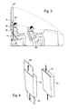
- the jump seat 12 then proposes, as illustrated on the figure 3 , a raised seat relative to the seat of the seats 30 for the driver and co-driver, to take into account in particular the recoil of the jump seat 12 relative to the seats 30.
- the jump seat 12 is also preferably arranged in a median position relative to the longitudinal axis of the aircraft and is thus in a retracted and median position relative to the seats 30.
- the seat 20 of the jump seat 12 may have a height adjustable position. Such an adjustment can be made using for example indexed strips (not shown) arranged on either side of the corridor can be manually adjusted. An electric adjustment can also be envisaged using a system with pinion (s) and rack (s) or a cable system (s) and pulley (s).
- the seat 20 When the jump seat is used to receive an observer (during for example a pilot training phase) the seat 20 will be set in its highest position.
- the seat When the jump seat is used to accommodate a member of the technical staff and avoid the use of a seat in the cabin, the seat will be set in a low position, the lowest position, an intermediate position depending eg on the morphology of the person using the jump seat.
- the proposed solution allows a security of the cockpit. It is indeed necessary on an aircraft to provide an aircraft front portion configuration to prevent forced intrusion of the cabin to the cockpit. Solutions using partition walls and secure doors with shields and optical peepholes are then proposed. However, when exiting a cockpit occupant, however short this exit, it is necessary to avoid that the cabin area is in communication with the piloting area. It is thus known to have an isolation lock between the cabin area and the pilot area, but the solutions proposed are most often penalizing because the presence of the airlock disrupts the layout of the cabin. cabin by taking volume, and thus potentially reducing the number of seats and therefore the potential earnings of the aircraft. In addition, the integration of such an airlock in a front part of aircraft is penalizing in terms of weight and cost.
- the proposed configuration on the figure 1 allows to realize such a security lock which is not penalizing.
- the rear central area of the cockpit which comprises the corridor 10 and which is associated with the folding seat 12 articulated on the side structures of this corridor allows a good integration of the security lock.
- the jump seat 12, the corridor 10 and the door 6 thus provide a safety lock that does not have the disadvantages described above security locks of the prior art.
- This airlock is indeed integrated into the front part of the aircraft by limiting any overweight and any encroachment on the cabin area.
- the jump seat 12 will advantageously have some features, which remain however optional.
- the rear part of the seat, the backrest and the headrest will be reinforced by a shell, preferably a shell resistant to the impact of a bullet fired by a handgun.
- the back of the seat corresponds to the part of the seat not used by an observer (or other occupant of the jump seat). This definition of back face also applies to the backrest and the headrest. This orientation (front / rear) is consistent with the forward / backward orientation chosen for the chassis 14.
- the jump seat 12 In its first position A, the jump seat 12 will preferably have limited play with the structural uprights 22 between which it is located and between the jump seat and the ceiling and the ground.
- the clearances between the frame 14 and the structural uprights 22 will preferably be of the order of one millimeter in the first position A.
- figure 4 illustrates for its possible integration in the upper and lower part of the jump seat 12 each time a sliding plate 32.
- Each sliding plate 32 can take a deployed position out of the jump seat 12 (left side of the figure 4 ) and an retracted position (right side of the figure 4 ).
- Sliding plates 32 are advantageously shielded and are intended to seal the upper space and the lower space of the corridor, giving the appearance of a complete closure, as would a door.
- the locking means 24 of the jump seat for locking it in its first position A are advantageously operable on both sides of the jump seat 12 when it is in this first position but it is preferable to provide that it is possible, from the seats 30 of the pilot and co-pilot, to prohibit unlocking of these locking means 24 from the corridor 10.
- jump seat 12 with a control system, such as for example an optical peephole (not shown).
- a video camera surveillance of the corridor 10 may also be provided as a replacement for or in addition to the optical peephole.
- the front part of the aircraft comprises, below the cockpit, usually a technical compartment to which it can be accessed by a hatch. It is assumed here that the aircraft considered has such a lower bunker. Its access is then provided by the lower hatch 26 which is advantageously and originally arranged in the corridor 10, just behind the jump seat 12 when it is in the closed position corresponding to the first position A.
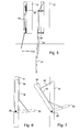
- a ladder In an original way, as illustrated schematically on the figure 5 it is proposed to integrate the back of the jump seat 12 a ladder.
- the latter is for example a two-strand ladder 34, one of which slides relative to the other.
- These two ladder strands 34 are mounted on the rear face of the jump seat 12, for example on the rear face of the frame 14, by means of a double deformable parallelogram 36 (a parallelogram on each side of the ladder).
- the double deformable parallelogram 36 makes it possible to ensure the offset of the ladder with respect to the jump seat 12 as illustrated on the right-hand side of the figure 5 .
- the scale may have only one strand (or on the contrary three or more strands).
- the lower hatch 26 is advantageously arranged in the passage 10 so that when the jump seat 12 is in its first position A, and said hatch is open, the strands 34 of the ladder are deployed so that they " fall "in the technical hold.
- the scale of access to the technical cargo does not penalize the volume of the latter (nor does it penalize the volume of the cockpit).
- someone then wants to access the technical compartment it comes to lock the jump seat 12 in its first position A, it opens the lower door 26, down the ladder through the lower door 26, and can then access the technical compartment .
- the present invention also takes into account emergency evacuations of cockpits. It is foreseen by regulation to allow an emergency evacuation in case of crash of the whole staff of the cockpit in a very short time.
- the present invention provides an evacuation through the roof. It is noted for this purpose the presence of the upper hatch 28 on the figure 1 . It is proposed, quite original way, to use the jump seat 12 to perform such an evacuation.
- the jump seat 12 is then positioned in its second position B, or rear storage position, in the corridor 10. It is then expected, in this position, to lower the seat 20 so that it comes in its substantially horizontal position . It can then be used as an access step to the upper hatch 28.
- the size of the seat 20 being very large (relative to a step or ladder step), the seat 20 can be used to to give the impulse and thus get out more easily through the upper hatch 28. In this way, the exit procedure is simplified and secure.
- the third seat is intended for very occasional use. It is, however, increasingly being used by airlines as an additional seat, allowing a company to fly its technical staff at a low cost without occupying a paying cabin seat. It happens that the third seat is used for relatively long flights. The comfort of this seat is preferably improved compared to a basic folding seat.
- the jump seat 12 When a passenger (technical staff for example) uses the third seat of the cockpit, the jump seat 12 according to the present invention is in its first position A. In the original configuration suggested by the present invention, the space at the rear of this third seat, that of the corridor 10, is not used. It can then be used to increase the comfort of the passenger as illustrated on the Figures 6 and 7 . The corresponding seat can be tilted backwards.
- a system of two pivots 38 and a system of two connecting rods 40 are provided.
- the two pivots 38 are mounted laterally at the seat 20 so as to allow pivoting of the seat 20 and the backrest 18 relative to the frame 14.
- the two rods 40 are provided on either side of the assembly formed by the backrest 18 and the seat 20 and connect this assembly to the frame 14.
- Each link 40 is pivotally mounted on the frame 14 and is attached to the backrest 18 , For example near the headrest 16.
- the connecting rods can also be replaced by straps, possibly adjustable.
- FIG. 8 An alternative embodiment of a folding seat according to the present invention is shown in the figures 8 and 9 .
- the jump seat there is for the jump seat a seat 20, a backrest 18 and a headrest 16. These various elements are mounted on a frame 44. The latter is pivotally mounted relative to the structural upright 22a via on the one hand, an intermediate profile 46 and, on the other hand, double hinges 48.
- the intermediate profile 46 comes to follow the shape of the structural upright 22a and can slide on it.
- the intermediate profile 46 is a U-shaped section having a base of flat shape whose width is adapted to the amount structural 22a and two lateral branches between which takes place the structural upright 22a so that the intermediate section 46 can slide by limiting the play along the structural amount 22a. In this way, a height adjustment of the jump seat can be achieved. For this height adjustment, the intermediate profile 46 slides along the structural upright 22a to the desired position.
- the double hinges 48 (only one of which is visible on the figure 8 ) are arranged between the intermediate section 46 and the frame 44. These hinges allow, as for the embodiment described above, the frame 44 to rotate more than 180 °, for example up to 270 °.
- a horizontal pivot axis 52 and a horizontal locking pin 54 are provided on the side of the frame 44 opposite the side carrying the double hinges 48.
- the horizontal pivot axis 52 extends through the frame 44 and engages in the intermediate section 46.
- This horizontal pivot axis 52 is thus advantageously used both as an axis to pivot the seat 20 of the seat relative to the seat. to the frame 44 and as an axis for pivoting the entire frame 44 relative to its environment, in particular here the intermediate section 46 and the structural uprights 22a and 22b.
- the visible end on the figure 8 the horizontal pivot axis 52 can retract towards the inside of the frame 44 or come into engagement with the structural post 22b or an intermediate piece (not shown) similar to the intermediate piece 46 and mounted on the structural post 22b .
- the frame 44 In the first position, the rotation around the double hinges 48 is free; in the second position, the frame 44 can pivot about the horizontal pivot axis 52 by releasing the double hinges 48.
- the pivot axis horizontal 52 participates in the second position in the locking frame 44 in its pivoting movement about a vertical axis.
- the locking pin 54 is a retractable shaft which can be housed inside the frame 44 or projecting out of it to cooperate with the structural post 22b (or the intermediate piece not shown and mentioned above) which is on the structural post 22b and similar to the intermediate piece 46) and vertically locking the frame 44 between the two structural posts 22a and 22b.
- a lever 56 makes it possible to act on an internal linkage to the chassis 44 to control either the locking of the chassis in its aligned position between the two structural uprights 22a and 22b, or to allow horizontal pivoting or to allow vertical pivoting.
- a mechanism internal to the frame similar to a so-called swinging door or window mechanism.
- the figure 9 illustrates how a sliding plate like the one shown on the figure 4 and a scale like the one shown on the figure 5 can be adapted and integrated into the jump seat of the figure 8 .
- This figure 9 is a partial section according to a horizontal sectional plan and on an enlarged scale of an edge of the jump seat.
- the cutting plane chosen passes through the backrest 18 of the jump seat.
- a housing 58 closed by a cover 60 in which the sliding plate 32 is housed and from which it can exit, for example upwards.
- a sliding plate also housed in the housing 58 can come close a lower free space between the jump seat and the floor of the corridor 10.
- the frame 44 carries two strands 34 of scale. These ladder strands 34 are carried by arms 64, only one of which is visible here. As illustrated, the fasteners of the cover 60 can be used to attach the arms 64 to the frame 44.
- a plate 68 ( figure 9 ) is pivotally mounted about an axis of pivoting 66 to allow a pivotal movement of the scale about a substantially horizontal axis. Compared to the figure 5 the plate 68 corresponds to two arms 36, an arm 36 of a deformable parallelogram on one side of the scale and another arm 36 of the other deformable parallelogram on the other side of the scale.
- a first strand 34 of the ladder is hingedly mounted to the top of the upper plate 68 as shown in FIG. figure 9 , the axis of articulation of the strand 34 being able to be merged with the hinge axis 66.
- the present invention thus proposes, on the one hand, an original folding seat and, on the other hand, an arrangement of the front part of an original aircraft incorporating such a folding seat.
- the jump seat can take several storage positions to promote the ergonomics of the corresponding cockpit.
- the various adjustments that can be made to the jump seat allow it to be versatile.
- the jump seat can be used by an observer (preferably with the seat adjusted to its highest position to promote good visualization of the instruments and through the windshield) or by a staff member even on long flights.
- the proposed development of the cockpit provides a high degree of security vis-à-vis an intrusion of the cabin to the cockpit without additional mass sensitive. It should be noted in this regard that the panels of the partition wall between the cockpit and the cabin area do not need to be shielded (or can be only slightly shielded) since they are against the system cabinets placed in the cockpit. An attack against these panels is unlikely to succeed because the system cabinets reinforce them "naturally”.
- the proposed layout also presents original solutions, on the one hand, for access to a technical bunker located below the cockpit and, on the other hand, for an emergency evacuation to the top of the members of crew in the cockpit in the event of an accident.
Landscapes
- Engineering & Computer Science (AREA)
- Aviation & Aerospace Engineering (AREA)
- Mechanical Engineering (AREA)
- Seats For Vehicles (AREA)
- Air Bags (AREA)
Applications Claiming Priority (1)
| Application Number | Priority Date | Filing Date | Title |
|---|---|---|---|
| FR1158792A FR2980773B1 (fr) | 2011-09-30 | 2011-09-30 | Strapontin pour cockpit d'aeronef et partie avant d'aeronef equipee d'un tel strapontin |
Publications (3)
| Publication Number | Publication Date |
|---|---|
| EP2574551A2 true EP2574551A2 (de) | 2013-04-03 |
| EP2574551A3 EP2574551A3 (de) | 2013-10-23 |
| EP2574551B1 EP2574551B1 (de) | 2016-08-31 |
Family
ID=46880643
Family Applications (1)
| Application Number | Title | Priority Date | Filing Date |
|---|---|---|---|
| EP12186328.6A Not-in-force EP2574551B1 (de) | 2011-09-30 | 2012-09-27 | Cockpit eines Luftfahrzeugs mit einen Notsitz |
Country Status (5)
| Country | Link |
|---|---|
| US (1) | US9340293B2 (de) |
| EP (1) | EP2574551B1 (de) |
| CN (1) | CN103072693B (de) |
| CA (1) | CA2791173C (de) |
| FR (1) | FR2980773B1 (de) |
Cited By (2)
| Publication number | Priority date | Publication date | Assignee | Title |
|---|---|---|---|---|
| WO2017050912A1 (fr) * | 2015-09-22 | 2017-03-30 | Zodiac Seats France | Arrangement de cabine d'aéronef optimisé pour l'intégration de sièges pour personnel navigant |
| US10479508B2 (en) | 2016-07-11 | 2019-11-19 | Airbus Helicopters | Jumpseat, and a vehicle provided with the jumpseat |
Families Citing this family (18)
| Publication number | Priority date | Publication date | Assignee | Title |
|---|---|---|---|---|
| DE102011116521A1 (de) * | 2011-10-20 | 2013-04-25 | Airbus Operations Gmbh | Drehbarer Flugbegleitersitz und Flugzeugmonumentbaugruppe mit einem drehbaren Flugbegleitersitz |
| DE102012023045A1 (de) * | 2012-11-26 | 2014-05-28 | Airbus Operations Gmbh | Flugbegleitersitzanordnung |
| EP2743183A1 (de) * | 2012-12-14 | 2014-06-18 | Airbus Operations GmbH | Umwandelbarer Fahrgastraum-Beifahrersitz |
| DE102013008289A1 (de) * | 2013-05-15 | 2014-11-20 | Airbus Operations Gmbh | Flugzeugbereich |
| DE102014102378A1 (de) * | 2014-02-24 | 2015-08-27 | Airbus Operations Gmbh | Modul für eine Luftfahrzeugkabine mit einem an einer Tür angebrachten Sitz |
| DE102014104921A1 (de) * | 2014-04-07 | 2015-10-08 | Airbus Operations Gmbh | Haltesystem für eine bewegliche Komponente |
| US9688168B2 (en) * | 2014-06-25 | 2017-06-27 | S2 Yachts, Inc. | Integrated seat and backrest |
| US10470578B2 (en) * | 2014-07-14 | 2019-11-12 | Seth EHLINGER | Wall mounted collapsible chair |
| US9783271B2 (en) * | 2015-01-23 | 2017-10-10 | Boston Whaler, Inc. | Flipping conversion seat and lean post |
| FR3036098B1 (fr) * | 2015-05-12 | 2017-05-12 | Airbus Operations Sas | Dispositif d'acces a paroi pliante permettant la communication securisee entre au moins deux zones d'une enceinte |
| DE102015116798B4 (de) | 2015-10-02 | 2024-03-28 | Airbus Operations Gmbh | Raumoptimierte Kabinenanordnung für ein Fahrzeug sowie eine Passagierkabine mit einer Mehrzahl von Sitzen und einer solchen Kabinenanordnung |
| US9840332B2 (en) * | 2015-10-15 | 2017-12-12 | The Boeing Company | Deployable door-mounted seat |
| US10065711B2 (en) | 2016-02-05 | 2018-09-04 | S2 Yachts Inc. | Multiple position boat seat |
| US10329021B2 (en) * | 2016-12-16 | 2019-06-25 | Ami Industries, Inc. | Collapsible backrest |
| FR3075173B1 (fr) * | 2017-12-19 | 2019-11-15 | Airbus Operations (S.A.S.) | Siege de pilote muni d'une echelle d'evacuation et aeronef muni d'un tel siege |
| FR3093703B1 (fr) * | 2019-03-12 | 2021-06-18 | Airbus Operations Sas | Meuble pour aeronef comportant au moins un ecran d’affichage de donnees de vol et au moins un module avionique |
| GB2586043B (en) * | 2019-07-31 | 2023-05-10 | Safran Seats Gb Ltd | Aircraft passenger seat unit with movable panel |
| CN114919751B (zh) * | 2022-04-08 | 2025-04-18 | 中国商用飞机有限责任公司 | 用于舱体的逃生装置、舱组件、交通工具及逃生方法 |
Citations (5)
| Publication number | Priority date | Publication date | Assignee | Title |
|---|---|---|---|---|
| FR2547273A1 (fr) | 1983-06-08 | 1984-12-14 | Aerospatiale | Procede pour l'agencement d'un poste de pilotage d'aeronef de type ergonomique et poste de pilotage ainsi agence |
| EP0282541A1 (de) | 1986-09-19 | 1988-09-21 | Messerschmitt Boelkow Blohm | Schwenkbarer sitz, insbesondere für einen flugbegleiter. |
| EP0349762A2 (de) | 1988-07-04 | 1990-01-10 | Deutsche Airbus GmbH | Sitz, insbesondere für einen Flugbegleiter |
| FR2900634A1 (fr) | 2006-05-04 | 2007-11-09 | Airbus France Sas | Amenagement de poste de pilotage pour aeronef |
| FR2903661A1 (fr) | 2006-07-12 | 2008-01-18 | Airbus France Sas | Avion de transport de passagers |
Family Cites Families (10)
| Publication number | Priority date | Publication date | Assignee | Title |
|---|---|---|---|---|
| US3594037A (en) * | 1970-04-09 | 1971-07-20 | Mc Donnell Douglas Corp | Cabin attendant seat |
| US6702231B2 (en) * | 2001-10-10 | 2004-03-09 | Gary Ward | Door system for creating and maintaining a secured area |
| US20050116098A1 (en) * | 2002-01-09 | 2005-06-02 | Larry Martens | Flight deck security system |
| US6659401B1 (en) * | 2002-11-13 | 2003-12-09 | Robert M. Semprini | Airplane door lock system |
| US7014148B2 (en) * | 2003-10-21 | 2006-03-21 | Armando Dominguez | Cockpit security door/restroom |
| RU2403188C2 (ru) * | 2004-08-03 | 2010-11-10 | Эрбюс | Внутренняя предохранительная дверь для воздушного судна |
| RU2382719C2 (ru) * | 2004-08-03 | 2010-02-27 | Эрбюс | Усиленная дверь |
| FR2886622B1 (fr) | 2005-06-02 | 2007-07-20 | Airbus France Sas | Avion long-courrier |
| DE102007041391A1 (de) * | 2007-08-31 | 2009-03-05 | Airbus Deutschland Gmbh | Gesichertes Cockpit mit integriertem Aufenthaltsbereich und Sanitäranlagen |
| US7984875B2 (en) * | 2007-09-11 | 2011-07-26 | The Boeing Company | Multi-position secure door system |
-
2011
- 2011-09-30 FR FR1158792A patent/FR2980773B1/fr not_active Expired - Fee Related
-
2012
- 2012-09-21 CA CA2791173A patent/CA2791173C/fr not_active Expired - Fee Related
- 2012-09-27 US US13/628,206 patent/US9340293B2/en not_active Expired - Fee Related
- 2012-09-27 EP EP12186328.6A patent/EP2574551B1/de not_active Not-in-force
- 2012-09-28 CN CN201210597613.9A patent/CN103072693B/zh not_active Expired - Fee Related
Patent Citations (5)
| Publication number | Priority date | Publication date | Assignee | Title |
|---|---|---|---|---|
| FR2547273A1 (fr) | 1983-06-08 | 1984-12-14 | Aerospatiale | Procede pour l'agencement d'un poste de pilotage d'aeronef de type ergonomique et poste de pilotage ainsi agence |
| EP0282541A1 (de) | 1986-09-19 | 1988-09-21 | Messerschmitt Boelkow Blohm | Schwenkbarer sitz, insbesondere für einen flugbegleiter. |
| EP0349762A2 (de) | 1988-07-04 | 1990-01-10 | Deutsche Airbus GmbH | Sitz, insbesondere für einen Flugbegleiter |
| FR2900634A1 (fr) | 2006-05-04 | 2007-11-09 | Airbus France Sas | Amenagement de poste de pilotage pour aeronef |
| FR2903661A1 (fr) | 2006-07-12 | 2008-01-18 | Airbus France Sas | Avion de transport de passagers |
Cited By (3)
| Publication number | Priority date | Publication date | Assignee | Title |
|---|---|---|---|---|
| WO2017050912A1 (fr) * | 2015-09-22 | 2017-03-30 | Zodiac Seats France | Arrangement de cabine d'aéronef optimisé pour l'intégration de sièges pour personnel navigant |
| US10875653B2 (en) | 2015-09-22 | 2020-12-29 | Safran Seats | Aircraft cabin arrangement optimised for the installation of seats for the flight crew |
| US10479508B2 (en) | 2016-07-11 | 2019-11-19 | Airbus Helicopters | Jumpseat, and a vehicle provided with the jumpseat |
Also Published As
| Publication number | Publication date |
|---|---|
| CN103072693A (zh) | 2013-05-01 |
| EP2574551B1 (de) | 2016-08-31 |
| US9340293B2 (en) | 2016-05-17 |
| CN103072693B (zh) | 2016-09-28 |
| US20130126671A1 (en) | 2013-05-23 |
| CA2791173A1 (fr) | 2013-03-30 |
| CA2791173C (fr) | 2019-02-19 |
| EP2574551A3 (de) | 2013-10-23 |
| FR2980773A1 (fr) | 2013-04-05 |
| FR2980773B1 (fr) | 2013-10-25 |
Similar Documents
| Publication | Publication Date | Title |
|---|---|---|
| EP2574551B1 (de) | Cockpit eines Luftfahrzeugs mit einen Notsitz | |
| EP2094563B1 (de) | Vorderteil für ein flugzeug mit einem ruhebereich für mindestens einen piloten | |
| EP3606817B1 (de) | Durchgangssperre zwischen nebeneinander angeordneten sitzen | |
| EP2749492B1 (de) | Cockpit eines Luftfahrzeugs mit Notausgang durch eine zentrale Glasscheibe | |
| EP2569216B1 (de) | Sitzbasis mit kontrolliertem und optimiertem weg und zugheöriger sitz | |
| EP2496476B1 (de) | Flugzeugkabine mit sicherheitsschleuse zum cockpit | |
| FR3036098A1 (fr) | Dispositif d'acces a paroi pliante permettant la communication securisee entre au moins deux zones d'une enceinte | |
| EP3898413B1 (de) | Vorrichtung zum schliessen einer passage zwischen zwei sitzen | |
| FR2962714A1 (fr) | Strapontin pour un poste de pilotage d'aeronef | |
| EP4259523B1 (de) | Sitzeinheit mit faltbarem sichtschutzschild | |
| WO2020020658A1 (fr) | Module double portes pour sieges d'avion | |
| FR2865162A1 (fr) | Dispositif de fermeture pour vehicule pourvu d'un hayon arriere et d'un toit ouvrant | |
| EP3999421B1 (de) | Sitzanordnungen, insbesondere für eine flugzeugkabine | |
| FR2910435A1 (fr) | Compartiment de repos pour pilote d'aeronef. | |
| EP4281360A1 (de) | Verfahren und anordnung zur bereitstellung einer stabilisierungsführung für eine fahrzeugtür mit pleuelstangenverriegelung | |
| EP3962812B1 (de) | Sitzgruppe, insbesondere für flugzeuge | |
| FR3079496A1 (fr) | Enceinte de stockage au niveau d'un renfoncement dans une cloison de separation entre cockpit et cabine et aeronef muni d'au moins une telle enceinte | |
| EP3524476B1 (de) | Abschirmungsvorrichtung für fahrzeug | |
| EP1706283B1 (de) | Ein sonnendach und eine luke umfassendes fahrzeug | |
| CA3199801A1 (fr) | Dispositif de support pour un ensemble d'amenagement interieur d'une cabine d'aeronef, ensemble et procede associes | |
| FR3073818A1 (fr) | Element de separation pour cabine de plateforme, plateforme comprenant un tel element et procede d'utilisation d'un tel element | |
| FR3117453A1 (fr) | Unité de siege munie d'une coque d'intimite escamotable | |
| FR2886969A1 (fr) | Porte de compartiment de type coffre a bagages |
Legal Events
| Date | Code | Title | Description |
|---|---|---|---|
| PUAI | Public reference made under article 153(3) epc to a published international application that has entered the european phase |
Free format text: ORIGINAL CODE: 0009012 |
|
| AK | Designated contracting states |
Kind code of ref document: A2 Designated state(s): AL AT BE BG CH CY CZ DE DK EE ES FI FR GB GR HR HU IE IS IT LI LT LU LV MC MK MT NL NO PL PT RO RS SE SI SK SM TR |
|
| AX | Request for extension of the european patent |
Extension state: BA ME |
|
| PUAL | Search report despatched |
Free format text: ORIGINAL CODE: 0009013 |
|
| AK | Designated contracting states |
Kind code of ref document: A3 Designated state(s): AL AT BE BG CH CY CZ DE DK EE ES FI FR GB GR HR HU IE IS IT LI LT LU LV MC MK MT NL NO PL PT RO RS SE SI SK SM TR |
|
| AX | Request for extension of the european patent |
Extension state: BA ME |
|
| RIC1 | Information provided on ipc code assigned before grant |
Ipc: B64D 11/06 20060101AFI20130913BHEP Ipc: B64D 45/00 20060101ALI20130913BHEP |
|
| 17P | Request for examination filed |
Effective date: 20140325 |
|
| RBV | Designated contracting states (corrected) |
Designated state(s): AL AT BE BG CH CY CZ DE DK EE ES FI FR GB GR HR HU IE IS IT LI LT LU LV MC MK MT NL NO PL PT RO RS SE SI SK SM TR |
|
| GRAP | Despatch of communication of intention to grant a patent |
Free format text: ORIGINAL CODE: EPIDOSNIGR1 |
|
| INTG | Intention to grant announced |
Effective date: 20160615 |
|
| GRAS | Grant fee paid |
Free format text: ORIGINAL CODE: EPIDOSNIGR3 |
|
| GRAA | (expected) grant |
Free format text: ORIGINAL CODE: 0009210 |
|
| AK | Designated contracting states |
Kind code of ref document: B1 Designated state(s): AL AT BE BG CH CY CZ DE DK EE ES FI FR GB GR HR HU IE IS IT LI LT LU LV MC MK MT NL NO PL PT RO RS SE SI SK SM TR |
|
| REG | Reference to a national code |
Ref country code: CH Ref legal event code: EP Ref country code: GB Ref legal event code: FG4D Free format text: NOT ENGLISH |
|
| REG | Reference to a national code |
Ref country code: IE Ref legal event code: FG4D Free format text: LANGUAGE OF EP DOCUMENT: FRENCH |
|
| REG | Reference to a national code |
Ref country code: FR Ref legal event code: PLFP Year of fee payment: 5 |
|
| REG | Reference to a national code |
Ref country code: DE Ref legal event code: R096 Ref document number: 602012022337 Country of ref document: DE |
|
| REG | Reference to a national code |
Ref country code: AT Ref legal event code: REF Ref document number: 824730 Country of ref document: AT Kind code of ref document: T Effective date: 20161015 |
|
| REG | Reference to a national code |
Ref country code: LT Ref legal event code: MG4D |
|
| REG | Reference to a national code |
Ref country code: NL Ref legal event code: MP Effective date: 20160831 |
|
| REG | Reference to a national code |
Ref country code: AT Ref legal event code: MK05 Ref document number: 824730 Country of ref document: AT Kind code of ref document: T Effective date: 20160831 |
|
| PG25 | Lapsed in a contracting state [announced via postgrant information from national office to epo] |
Ref country code: RS Free format text: LAPSE BECAUSE OF FAILURE TO SUBMIT A TRANSLATION OF THE DESCRIPTION OR TO PAY THE FEE WITHIN THE PRESCRIBED TIME-LIMIT Effective date: 20160831 Ref country code: NO Free format text: LAPSE BECAUSE OF FAILURE TO SUBMIT A TRANSLATION OF THE DESCRIPTION OR TO PAY THE FEE WITHIN THE PRESCRIBED TIME-LIMIT Effective date: 20161130 Ref country code: LT Free format text: LAPSE BECAUSE OF FAILURE TO SUBMIT A TRANSLATION OF THE DESCRIPTION OR TO PAY THE FEE WITHIN THE PRESCRIBED TIME-LIMIT Effective date: 20160831 Ref country code: FI Free format text: LAPSE BECAUSE OF FAILURE TO SUBMIT A TRANSLATION OF THE DESCRIPTION OR TO PAY THE FEE WITHIN THE PRESCRIBED TIME-LIMIT Effective date: 20160831 Ref country code: HR Free format text: LAPSE BECAUSE OF FAILURE TO SUBMIT A TRANSLATION OF THE DESCRIPTION OR TO PAY THE FEE WITHIN THE PRESCRIBED TIME-LIMIT Effective date: 20160831 |
|
| PG25 | Lapsed in a contracting state [announced via postgrant information from national office to epo] |
Ref country code: LV Free format text: LAPSE BECAUSE OF FAILURE TO SUBMIT A TRANSLATION OF THE DESCRIPTION OR TO PAY THE FEE WITHIN THE PRESCRIBED TIME-LIMIT Effective date: 20160831 Ref country code: SE Free format text: LAPSE BECAUSE OF FAILURE TO SUBMIT A TRANSLATION OF THE DESCRIPTION OR TO PAY THE FEE WITHIN THE PRESCRIBED TIME-LIMIT Effective date: 20160831 Ref country code: GR Free format text: LAPSE BECAUSE OF FAILURE TO SUBMIT A TRANSLATION OF THE DESCRIPTION OR TO PAY THE FEE WITHIN THE PRESCRIBED TIME-LIMIT Effective date: 20161201 Ref country code: AT Free format text: LAPSE BECAUSE OF FAILURE TO SUBMIT A TRANSLATION OF THE DESCRIPTION OR TO PAY THE FEE WITHIN THE PRESCRIBED TIME-LIMIT Effective date: 20160831 Ref country code: NL Free format text: LAPSE BECAUSE OF FAILURE TO SUBMIT A TRANSLATION OF THE DESCRIPTION OR TO PAY THE FEE WITHIN THE PRESCRIBED TIME-LIMIT Effective date: 20160831 Ref country code: BE Free format text: LAPSE BECAUSE OF NON-PAYMENT OF DUE FEES Effective date: 20160930 Ref country code: ES Free format text: LAPSE BECAUSE OF FAILURE TO SUBMIT A TRANSLATION OF THE DESCRIPTION OR TO PAY THE FEE WITHIN THE PRESCRIBED TIME-LIMIT Effective date: 20160831 |
|
| PG25 | Lapsed in a contracting state [announced via postgrant information from national office to epo] |
Ref country code: RO Free format text: LAPSE BECAUSE OF FAILURE TO SUBMIT A TRANSLATION OF THE DESCRIPTION OR TO PAY THE FEE WITHIN THE PRESCRIBED TIME-LIMIT Effective date: 20160831 Ref country code: EE Free format text: LAPSE BECAUSE OF FAILURE TO SUBMIT A TRANSLATION OF THE DESCRIPTION OR TO PAY THE FEE WITHIN THE PRESCRIBED TIME-LIMIT Effective date: 20160831 |
|
| REG | Reference to a national code |
Ref country code: CH Ref legal event code: PL |
|
| PG25 | Lapsed in a contracting state [announced via postgrant information from national office to epo] |
Ref country code: DK Free format text: LAPSE BECAUSE OF FAILURE TO SUBMIT A TRANSLATION OF THE DESCRIPTION OR TO PAY THE FEE WITHIN THE PRESCRIBED TIME-LIMIT Effective date: 20160831 Ref country code: PL Free format text: LAPSE BECAUSE OF FAILURE TO SUBMIT A TRANSLATION OF THE DESCRIPTION OR TO PAY THE FEE WITHIN THE PRESCRIBED TIME-LIMIT Effective date: 20160831 Ref country code: SK Free format text: LAPSE BECAUSE OF FAILURE TO SUBMIT A TRANSLATION OF THE DESCRIPTION OR TO PAY THE FEE WITHIN THE PRESCRIBED TIME-LIMIT Effective date: 20160831 Ref country code: PT Free format text: LAPSE BECAUSE OF FAILURE TO SUBMIT A TRANSLATION OF THE DESCRIPTION OR TO PAY THE FEE WITHIN THE PRESCRIBED TIME-LIMIT Effective date: 20170102 Ref country code: BG Free format text: LAPSE BECAUSE OF FAILURE TO SUBMIT A TRANSLATION OF THE DESCRIPTION OR TO PAY THE FEE WITHIN THE PRESCRIBED TIME-LIMIT Effective date: 20161130 Ref country code: CZ Free format text: LAPSE BECAUSE OF FAILURE TO SUBMIT A TRANSLATION OF THE DESCRIPTION OR TO PAY THE FEE WITHIN THE PRESCRIBED TIME-LIMIT Effective date: 20160831 Ref country code: SM Free format text: LAPSE BECAUSE OF FAILURE TO SUBMIT A TRANSLATION OF THE DESCRIPTION OR TO PAY THE FEE WITHIN THE PRESCRIBED TIME-LIMIT Effective date: 20160831 |
|
| REG | Reference to a national code |
Ref country code: DE Ref legal event code: R097 Ref document number: 602012022337 Country of ref document: DE |
|
| REG | Reference to a national code |
Ref country code: IE Ref legal event code: MM4A |
|
| PG25 | Lapsed in a contracting state [announced via postgrant information from national office to epo] |
Ref country code: IT Free format text: LAPSE BECAUSE OF FAILURE TO SUBMIT A TRANSLATION OF THE DESCRIPTION OR TO PAY THE FEE WITHIN THE PRESCRIBED TIME-LIMIT Effective date: 20160831 |
|
| PLBE | No opposition filed within time limit |
Free format text: ORIGINAL CODE: 0009261 |
|
| STAA | Information on the status of an ep patent application or granted ep patent |
Free format text: STATUS: NO OPPOSITION FILED WITHIN TIME LIMIT |
|
| PG25 | Lapsed in a contracting state [announced via postgrant information from national office to epo] |
Ref country code: IE Free format text: LAPSE BECAUSE OF NON-PAYMENT OF DUE FEES Effective date: 20160927 Ref country code: LI Free format text: LAPSE BECAUSE OF NON-PAYMENT OF DUE FEES Effective date: 20160930 Ref country code: CH Free format text: LAPSE BECAUSE OF NON-PAYMENT OF DUE FEES Effective date: 20160930 |
|
| 26N | No opposition filed |
Effective date: 20170601 |
|
| PG25 | Lapsed in a contracting state [announced via postgrant information from national office to epo] |
Ref country code: LU Free format text: LAPSE BECAUSE OF NON-PAYMENT OF DUE FEES Effective date: 20160927 Ref country code: SI Free format text: LAPSE BECAUSE OF FAILURE TO SUBMIT A TRANSLATION OF THE DESCRIPTION OR TO PAY THE FEE WITHIN THE PRESCRIBED TIME-LIMIT Effective date: 20160831 |
|
| REG | Reference to a national code |
Ref country code: FR Ref legal event code: PLFP Year of fee payment: 6 |
|
| REG | Reference to a national code |
Ref country code: BE Ref legal event code: MM Effective date: 20160930 |
|
| PG25 | Lapsed in a contracting state [announced via postgrant information from national office to epo] |
Ref country code: HU Free format text: LAPSE BECAUSE OF FAILURE TO SUBMIT A TRANSLATION OF THE DESCRIPTION OR TO PAY THE FEE WITHIN THE PRESCRIBED TIME-LIMIT; INVALID AB INITIO Effective date: 20120927 Ref country code: CY Free format text: LAPSE BECAUSE OF FAILURE TO SUBMIT A TRANSLATION OF THE DESCRIPTION OR TO PAY THE FEE WITHIN THE PRESCRIBED TIME-LIMIT Effective date: 20160831 |
|
| PG25 | Lapsed in a contracting state [announced via postgrant information from national office to epo] |
Ref country code: MT Free format text: LAPSE BECAUSE OF FAILURE TO SUBMIT A TRANSLATION OF THE DESCRIPTION OR TO PAY THE FEE WITHIN THE PRESCRIBED TIME-LIMIT Effective date: 20160831 Ref country code: MC Free format text: LAPSE BECAUSE OF FAILURE TO SUBMIT A TRANSLATION OF THE DESCRIPTION OR TO PAY THE FEE WITHIN THE PRESCRIBED TIME-LIMIT Effective date: 20160831 Ref country code: MK Free format text: LAPSE BECAUSE OF FAILURE TO SUBMIT A TRANSLATION OF THE DESCRIPTION OR TO PAY THE FEE WITHIN THE PRESCRIBED TIME-LIMIT Effective date: 20160831 Ref country code: IS Free format text: LAPSE BECAUSE OF FAILURE TO SUBMIT A TRANSLATION OF THE DESCRIPTION OR TO PAY THE FEE WITHIN THE PRESCRIBED TIME-LIMIT Effective date: 20160831 Ref country code: TR Free format text: LAPSE BECAUSE OF FAILURE TO SUBMIT A TRANSLATION OF THE DESCRIPTION OR TO PAY THE FEE WITHIN THE PRESCRIBED TIME-LIMIT Effective date: 20160831 |
|
| REG | Reference to a national code |
Ref country code: FR Ref legal event code: PLFP Year of fee payment: 7 |
|
| PG25 | Lapsed in a contracting state [announced via postgrant information from national office to epo] |
Ref country code: AL Free format text: LAPSE BECAUSE OF FAILURE TO SUBMIT A TRANSLATION OF THE DESCRIPTION OR TO PAY THE FEE WITHIN THE PRESCRIBED TIME-LIMIT Effective date: 20160831 |
|
| PGFP | Annual fee paid to national office [announced via postgrant information from national office to epo] |
Ref country code: FR Payment date: 20190927 Year of fee payment: 8 Ref country code: DE Payment date: 20190918 Year of fee payment: 8 |
|
| PGFP | Annual fee paid to national office [announced via postgrant information from national office to epo] |
Ref country code: GB Payment date: 20190920 Year of fee payment: 8 |
|
| REG | Reference to a national code |
Ref country code: DE Ref legal event code: R119 Ref document number: 602012022337 Country of ref document: DE |
|
| GBPC | Gb: european patent ceased through non-payment of renewal fee |
Effective date: 20200927 |
|
| PG25 | Lapsed in a contracting state [announced via postgrant information from national office to epo] |
Ref country code: FR Free format text: LAPSE BECAUSE OF NON-PAYMENT OF DUE FEES Effective date: 20200930 Ref country code: DE Free format text: LAPSE BECAUSE OF NON-PAYMENT OF DUE FEES Effective date: 20210401 |
|
| PG25 | Lapsed in a contracting state [announced via postgrant information from national office to epo] |
Ref country code: GB Free format text: LAPSE BECAUSE OF NON-PAYMENT OF DUE FEES Effective date: 20200927 |