EP2574554A2 - System zur Detektion des Status eines Betankungsrohrs - Google Patents
System zur Detektion des Status eines Betankungsrohrs Download PDFInfo
- Publication number
- EP2574554A2 EP2574554A2 EP12382226A EP12382226A EP2574554A2 EP 2574554 A2 EP2574554 A2 EP 2574554A2 EP 12382226 A EP12382226 A EP 12382226A EP 12382226 A EP12382226 A EP 12382226A EP 2574554 A2 EP2574554 A2 EP 2574554A2
- Authority
- EP
- European Patent Office
- Prior art keywords
- nozzle
- receptacle
- accordance
- triggers
- sensor
- Prior art date
- Legal status (The legal status is an assumption and is not a legal conclusion. Google has not performed a legal analysis and makes no representation as to the accuracy of the status listed.)
- Granted
Links
Images


Classifications
-
- B—PERFORMING OPERATIONS; TRANSPORTING
- B64—AIRCRAFT; AVIATION; COSMONAUTICS
- B64D—EQUIPMENT FOR FITTING IN OR TO AIRCRAFT; FLIGHT SUITS; PARACHUTES; ARRANGEMENT OR MOUNTING OF POWER PLANTS OR PROPULSION TRANSMISSIONS IN AIRCRAFT
- B64D39/00—Refuelling during flight
- B64D39/06—Connecting hose to aircraft; Disconnecting hose therefrom
Definitions
- the present invention refers to a system for detecting the status of the connection of a tube employed for refueling or transferring fuel.
- it refers to a system for detecting the status of the connection with a telescoping tube employed during air to air refueling and transferring fuel from a tanker aircraft to a receiver aircraft.
- One of the methods currently used for operations of refueling or transferring comprises a telescoping tube, which in turn comprises a fixed part and a mobile part, having said mobile part the capacity to be extended telescopically with respect to the fixed part, carrying out in this manner the transfer of fuel from one tank to another.
- this telescoping tube is normally directed by an operator or boomer stationed in the tanker aircraft and who operates said telescoping tube until the end of the same, called the nozzle, makes contact with a receptacle in the receiver aircraft.
- the end of the tube or nozzle comprises some latches.
- the receptacle of the receiver aircraft comprises some triggers, normally activated by hydraulic means, said triggers having the purposes of attaching and blocking the nozzle of the telescoping tube by means of the clamps on said tube.
- the receptacle in the receiving aircraft that initiates disconnection of the telescoping tube of the receiving aircraft, directly retracting the triggers of the receptacle and generating an electrical signal that informs the boomer in the tanker aircraft of the disconnection.
- the boomer in the tanker aircraft can also free the latches on the nozzle of the telescoping tube, including with the triggers of the receptacle closed by means of an integrated independent disconnection in the nozzle.
- an electrical pulse is also generated to report the disconnection to the receptacle.
- the systems known in the state of the art control the connection and disconnection of the nozzle of the telescoping tube from the receptacle on the receiving aircraft by means of some systems of induction coils, a primary system of induction coils located in the nozzle and a system of secondary induction coils deployed in the receptacle in such a way that the connection or disconnection of the nozzle from the receptacle is controlled by the characteristics of the current induced in the primary and secondary induction coil systems which are facing each other.
- the secondary induction coil system induces a current in the primary induction coil system in the nozzle, and by means of visual observation on the part of the boomer, he is able to detect that the nozzle is connected to the receptacle, subsequently commencing the refueling sequence manually. All of this implies controlling a process that is extremely delicate in a manual way and by means of induced magnitudes, which is not, therefore, as trustworthy a process as would be desired.
- the receiving aircraft indicates the activation of the disconnecting mechanism, sending an electrical signal that causes an electrical current in the secondary coil system to be created, which induces an electrical current in the primary coil system of the nozzle, indicating to the boomer that the disconnection of the nozzle from the receptacle is going to proceed.
- the boomer in the tanker aircraft detects the disconnection process by means of induced measurements, and so the process is not as trustworthy as is should be for actions of this kind.
- the tanker aircraft In the case in which the boomer is the one who initiates the disconnection by the normal system or by the independent disconnection system, the tanker aircraft generates a current on the primary induction coil system that induces a voltage in the secondary induction system of the receptacle. In this way the receiving aircraft detects through induced means the intention of the boomer of the tanker aircraft to disconnect the nozzle, or free the latches of the nozzle. This system is not completely reliable as would be desired for actions of this type, as they are carried out through induced means.
- the present invention is directed towards providing these functions.
- the present invention refers to a system for carrying out the detection of the status of the connection of the nozzle of a telescoping tube employed in air to air refueling and transfer of fuel of a tanker aircraft with respect of the receptacle located on a receiving aircraft, such that this system is capable of the detection of the status of connection of the nozzle of the tanker aircraft in a direct manner without the need of taking measures in the receptacle or having to modify the configuration of said receptacle.
- the system of detection is much more reliable than those that currently existent in the state of the art.
- the system of detection of the invention comprises in turn the following devices:
- an indirect variant that acts on a solenoid in an independent system of disconnection
- a direct variant that detects the position of the latches in the nozzle
- the present invention refers to a nozzle 2 of a telescoping tube employed in the air to air refueling and transfer of fuel in a tanker aircraft, with respect to receptacle 4 located on a receiving aircraft, such that said nozzle 2 comprises a system for carrying out the detection of the status of the connection of nozzle 2 that is capable of carrying out the detection of the status of the connection of nozzle 2 to receptacle 4 in a direct manner by means of the measurement of parameters of nozzle 2 itself of the tanker aircraft, without the need of taking measurements in receptacle 4 or to modify the configuration of said receptacle 4.
- the system of detection comprises, in turn, the following devices to take the measurement of the selected parameters in nozzle 2 itself:
- the system of detection of the invention further comprises an independent disconnection device 50 of nozzle 2 of the telescoping tube.
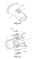
- Said device 50 comprises a solenoid 51 joined to a piston with a ramp shaped cam 52, as can be seen in Figure 1 .
- latches 6 of nozzle 2 rest on two pistons 53, 54 supported on rollers 55 that sustain the upper plane of piston with a ramp shaped cam 52
- solenoid 51, joined to said piston 52 is activated
- said piston 52 is displaced (towards the left according to its representation in Figure 1 ) dragged by solenoid 51, in such a way that the support of rollers 55 is withdrawn from pistons 53, 54, enabling the displacement of said rollers within their lodging guide 56, which in turn frees the displacement of latches 6 of nozzle 2, which are then pushed by an elastic element 7, preferably a spring, towards the center axel of nozzle 2.
- the system of the invention comprises a device 20 that reports the insertion of nozzle 2 on the telescoping tube into receptacle 4.
- detection of insertion device 20 of nozzle 2 of the telescoping tube into receptacle 4 carries out detection by inductance variation by means of coil 61 of the primary coil induction system of nozzle 2, which faces the secondary coil induction system of receptacle 4, being said induction coil 61 wrapped around an open magnetic nucleus, in such a way that each end of said nucleus represents a magnetic pole when current circulates through coil 61.
- the inductance of coil 61 varies in function of whether nozzle 2 is outside of or is inserted into receptacle 4, in such a way that the inductance is greater in the second case (when nozzle 2 is inserted into receptacle 4).
- device 20 measures the variation of inductance between the two previous cases, when nozzle 2 is inside receptacle 4 and when it is not.
- coil 61 is excited with alternate current, in such a way that the variation of inductance in said coil 61 is detected as a variation in the current, voltage, gap or resonance frequency of said alternating current.
- device 20 directly measures, preferably by means of an electronic circuit, the value or change in the inductance of coil 61 of the primary system of solenoids of nozzle 2, determining by said measurement value or by the detection of a change in the value whether or not coil 2 is inserted into receptacle 4.
- a permanent voltage excitation in coil 61 is used at a frequency greater than 20 KHz so that it is outside of audible range (it must be taken into account that the boomer and the operator in the receiving aircraft communicate by audio, and so this communication should not be interfered with).
- the current of coil 61 is measured, filtered by a high-pass filter to eliminate components of the signal in audio frequency and analyze the resulting current (by amplitude, frequency or gap), which depends on the inductance of coil 61. This action also enables detecting a possible presence or loss of coil 61 or of nozzle 2 due to lack of current.
- coil 61 is excited by voltage having a frequency higher than 20 KHz, with low amplitude, lower than 3V approximately, so as not to induce a pulse in the receptor, in such a way that the receiving aircraft does not interpret the excitation received as connection or disconnection pulse.
- Device 20 for detecting the insertion into nozzle 2 characterizes the inductance of coil 61 in both states (outside and inside receptacle 4), evaluating possible variations due to misalignments, gaps in rotation, etc. Device 20 does not involve making any physical modifications to nozzle 2, as it only requires developing an electronic excitation and signal conditioning.
- device 20 for detection of insertion into nozzle 2 on the telescoping tube into receptacle 4 performs a detection of displacement of a mobile element for the closing or opening of a cut off valve of the nozzle, in particular piston with a ramp shaped cam 60 that closes a cut off valve at the end of nozzle 2.
- a mobile element for the closing or opening of a cut off valve of the nozzle in particular piston with a ramp shaped cam 60 that closes a cut off valve at the end of nozzle 2.
- said receptacle pushes piston with a ramp shaped cam 60 of the cut off valve, in such a way that said cut off valve remains open to enable the transfer of fuel.
- the displacement of piston with a ramp shaped cam 60 is detected by means of device 20 that comprises a proximity sensor 90 attached to the body of nozzle 2.
- piston with a ramp shaped cam 60 comprises a magnet 91, preferably a magnet made of rare earth materials having a circular shape that is attached on the interior base of said piston with a ramp shaped cam 60.
- proximity sensor 90 is a hall type sensor or other type of proximity detector with other technology (for example, inductive, capacitive, etc.), and is placed in nozzle 2, not in receptacle 4, in such a way that the measurement it takes is direct, not induced.
- said proximity sensor 90 performs the measurement without contact, which provides additional advantages because for it to be able to function correctly there is no wear, no need for an exact alignment in nozzle 2, and it requires very little useful space for its maneuvering.
- the displacement of piston with a ramped shape cam 60 that closes the cut off valve at the end of nozzle 2 is taken advantage of for activating proximity sensor 90.
- the system of detection of the invention further comprises a device 30 for the detection of the status of triggers 6 of receptacle 4: it detects whether triggers 5 are open or closed.
- device 30 is added in nozzle 2 itself, in such a way that a direct measurement is performed on nozzle 2.
- Device 30 consists in adding to latches 6 of nozzle 2 a device 100 that is acted on directly by triggers 5 or receptacle 4, in such a way that the detection of the status of triggers 5 by the boomer in the tanker aircraft is direct and reliable.
- nozzle 2 is inside receptacle 4, said receptacle 4 activates a hydraulic actuator that closes its triggers 5.
- These triggers 5 overlap on latches 6 of nozzle 2, linking up with them in an axial direction for the transmission of the overall traction load.
- latches 6 of nozzle 2 comprise a scale device 100 in the presence of triggers 5 of receptacle 4.
- Said scale device 100 in the presence of triggers 5 of receptacle 4, is for activating a non contact proximity sensor 101, preferably a microswitch, which is the element that provides the indication of device 30.
- a non contact proximity sensor 101 preferably a microswitch, which is the element that provides the indication of device 30.
- Said microswitch 101 is placed (preferably screwed) on the cast body of nozzle 2, underneath latch 6 of nozzle 2, being activated upon approaching device 100, preferably an articulation on the same axis of the latches of the nozzle, for example, an articulated steel plate an the same axis of latch 6, such that said plate that forms device 100 is displaced by the presence of trigger 5 of receptacle 4.
- the connecting cables of microswitch 101 are available through the internal axel of nozzle 2. Consequently the changes to said nozzle 2 are minimal.
- the employed microswitches 101 are commercially available, having the capacity to work in an explosive atmosphere, for which reason microswitches having a hermetic capsule would be preferable.
- Another one of the possible embodiment of device 30 of the invention comprises at least one force sensor 510 deployed underneath latches 6 themselves of nozzle 2, in such a way that when triggers 5 of receptacle 6 latch onto latches 6 of nozzle 2, the force exercised by triggers 5 on latches 6 is measured by said force sensors.
- device 30 of the invention it is not necessary for device 30 of the invention to comprise device 100 acted on directly by triggers 5 of receptacle 4.
- Another one of the functionalities incorporated into the system of detection of the invention is that of detecting the status of latches 6 of nozzle 2, in such a way that it is determined whether said latches 6 are free or blocked.
- the system of detection comprises a device 40.
- device 40 receives information directly from independent disconnection device 50, in such a way that it is detected whether the blocking mechanism of latches 6 of nozzle 2 is free or blocked, by means of the inductance itself of solenoid 51 of independent disconnection device 50.
- solenoid coil 51 will take on very different values when latches 6 are blocked (solenoid 51 is not activated) and when latches 6 are freed, solenoid 51 being activated and, in consequence, independent disconnection device 50.
- device 40 develops an electronic excitation of solenoid 51 that detects the variation of inductance in said solenoid 51.
- device 40 comprises a high frequency excitation, preferably around 20 KHz, with several levels:
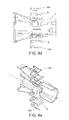
- the displacement of the nucleus of solenoid 51 is detected, which drags piston with a ramp shaped cam 52 of nozzle 2 of approximately 3 mm, a sufficient value for placing pistons 53, 54 in a position in which they could be moved by being pushed by latches 6 of nozzle 2 (see Figure 5 ).
- the detection of the status of the blocking mechanism of latches 6 of nozzle 2 is carried out directly from nozzle 6 itself, with no induced means whatsoever that could lead to mistakes being committed.
- the method described also enables detection of a possible loss of the coil of solenoid 51 of independent disconnection device 50 or of nozzle 2 due to lack of current.
- the implementation of the described functionality does not require any modifications to nozzle 2, only the characterization of solenoid 51 being needed.
- device 40 can detect in a direct manner the physical displacement of latches 6 of nozzle 2 from independent disconnection device 50. For the physical displacement of latches 6 to occur, it is necessary:
- independent disconnection device 50 is freed, but that latches 6 of nozzle 2 do not displace because the conditions of force on the nozzle have not occurred.
- piston with a ramp shaped cam 52 When solenoid 51 has been activated, piston with a ramp shaped cam 52 is displaced about 3mm, thus freeing independent disconnection device 50. In this position rollers 55, located between pistons 53, 54 and piston with ramp shaped cam 52, are supported above the inclined plane of piston with ramp shaped cam 52. The radial force exercised by latches 6 of the nozzle push pistons 53, 54 radially on inclined plane 61, forcing an axial displacement (towards the left in Figures 5 , 6, 7 ) of piston with ramp shaped cam 52. This displacement is transmitted through a rod 70 up to microswitch 80 integrated in the nucleus of solenoid 51 of independent disconnection device 50.
- microswitch 80 is only activated if latches 6 are in the free position.
- the electric cables of microswitch 80 are run through the same path as those of solenoid 51 of independent disconnection device 50.
Landscapes
- Engineering & Computer Science (AREA)
- Aviation & Aerospace Engineering (AREA)
- Loading And Unloading Of Fuel Tanks Or Ships (AREA)
Applications Claiming Priority (1)
| Application Number | Priority Date | Filing Date | Title |
|---|---|---|---|
| ES201130929 | 2011-06-03 |
Publications (3)
| Publication Number | Publication Date |
|---|---|
| EP2574554A2 true EP2574554A2 (de) | 2013-04-03 |
| EP2574554A3 EP2574554A3 (de) | 2017-04-05 |
| EP2574554B1 EP2574554B1 (de) | 2018-10-10 |
Family
ID=46548366
Family Applications (1)
| Application Number | Title | Priority Date | Filing Date |
|---|---|---|---|
| EP12382226.4A Active EP2574554B1 (de) | 2011-06-03 | 2012-06-01 | System zur Detektion des Status eines Betankungsrohrs |
Country Status (3)
| Country | Link |
|---|---|
| US (1) | US9193471B2 (de) |
| EP (1) | EP2574554B1 (de) |
| ES (1) | ES2705356T3 (de) |
Families Citing this family (5)
| Publication number | Priority date | Publication date | Assignee | Title |
|---|---|---|---|---|
| US10239631B2 (en) * | 2014-09-10 | 2019-03-26 | The Boeing Company | Aircraft receptacle |
| ES2659752T3 (es) * | 2015-04-27 | 2018-03-19 | Airbus Defence And Space, S.A. | Sistema y método de detección de contacto para un avión cisterna de reabastecimiento en vuelo equipado con un sistema de pértiga |
| US10913649B2 (en) * | 2017-09-01 | 2021-02-09 | Eaton Intelligent Power Limited | Fluid nozzle with one or more sensors |
| EP3765334A4 (de) | 2018-03-16 | 2022-03-23 | Fuelie Systems, Inc. | Vorrichtung zur lagerung und abgabe von kraftstoff |
| US11104448B2 (en) * | 2018-05-24 | 2021-08-31 | Eaton Intelligent Power Limited | Fluid nozzle |
Family Cites Families (10)
| Publication number | Priority date | Publication date | Assignee | Title |
|---|---|---|---|---|
| GB724159A (en) * | 1951-09-11 | 1955-02-16 | Boeing Co | Improvements in or relating to pipe joints |
| US4025193A (en) * | 1974-02-11 | 1977-05-24 | The Boeing Company | Apparatus suitable for use in orienting aircraft in-flight for refueling or other purposes |
| US4158885A (en) * | 1977-11-09 | 1979-06-19 | The Boeing Company | Guidance-light display apparatus and method for in-flight link-up of two aircraft |
| US4438793A (en) * | 1981-05-04 | 1984-03-27 | International Telephone & Telegraph Corp. | Aerial refueling boom nozzle |
| US20030136874A1 (en) * | 2001-12-10 | 2003-07-24 | Gjerdrum David Michael | Method for safer mid-air refueling |
| US7152828B1 (en) * | 2002-11-01 | 2006-12-26 | Sargent Fletcher, Inc. | Method and apparatus for the hookup of unmanned/manned (“hum”) multi purpose vehicles with each other |
| US6990945B1 (en) * | 2004-07-14 | 2006-01-31 | General Motors Corporation | Vehicle fueling arrangement |
| US8056619B2 (en) * | 2006-03-30 | 2011-11-15 | Schlumberger Technology Corporation | Aligning inductive couplers in a well |
| US7671482B2 (en) * | 2007-02-02 | 2010-03-02 | Gm Global Technology Operations, Inc. | Hydrogen powered vehicle refueling strategy |
| ES2390539B1 (es) * | 2010-01-08 | 2013-10-09 | Eads Construcciones Aeronauticas, S.A. | Sistema de desconexion de un tubo para el trasvase de combustible. |
-
2012
- 2012-03-01 US US13/409,299 patent/US9193471B2/en active Active
- 2012-06-01 ES ES12382226T patent/ES2705356T3/es active Active
- 2012-06-01 EP EP12382226.4A patent/EP2574554B1/de active Active
Non-Patent Citations (1)
| Title |
|---|
| None |
Also Published As
| Publication number | Publication date |
|---|---|
| US20120305710A1 (en) | 2012-12-06 |
| EP2574554A3 (de) | 2017-04-05 |
| EP2574554B1 (de) | 2018-10-10 |
| US9193471B2 (en) | 2015-11-24 |
| ES2705356T3 (es) | 2019-03-22 |
Similar Documents
| Publication | Publication Date | Title |
|---|---|---|
| EP2574554B1 (de) | System zur Detektion des Status eines Betankungsrohrs | |
| EP3278421B1 (de) | Induktiver stromsender | |
| CN108711953B (zh) | 由建筑材料制成的块 | |
| JP6467358B2 (ja) | 非接触給電装置及びエレベーター | |
| CN107636376A (zh) | 分离式联接器监测 | |
| CN105717468B (zh) | 对磁共振装置的高频线圈进行状态采集的装置和方法 | |
| DE102012205285A1 (de) | Vorrichtung zur induktiven Leistungsübertragung | |
| CN111655533B (zh) | 感应式充电装置和用于监控感应式充电装置的方法 | |
| CN110104925A (zh) | 污泥脱水及含水率检测方法 | |
| EP2343240B1 (de) | System zum Trennen eines Betankungsauslegers | |
| CN109923424A (zh) | 用于诊断电磁感应供电设备的故障的装置和方法 | |
| NO335844B1 (no) | Fôringsrørsentraliseringssystem og fremgangsmåte for sentralisering av et fôringsrør | |
| CN203176062U (zh) | 电液执行机构安全功能的检测装置 | |
| CN219694558U (zh) | 飞机空地信号的模拟转换装置及用于飞机试验的系统 | |
| CN109564107B (zh) | 监控两个元件的相对运动的设备、方法、能量消耗装置和耦连杆 | |
| CN204228662U (zh) | Pccp钢丝断丝检测车 | |
| CN216240605U (zh) | 检测装置及具有其的井口系统 | |
| WO2025072496A1 (en) | Electric vehicle charging connector adapter nested in an electric vehicle supply equipment | |
| CN214887036U (zh) | 铁磁性物体检测装置 | |
| CN102944739B (zh) | 大口径钳形交流微小电流传感器装置 | |
| EP4078107A1 (de) | Messvorrichtung zur erfassung eines füll- oder grenzstands eines füllguts in einem behälter sowie verfahren zum befüllen oder entleeren eines behälters mit bzw. von einem füllgut | |
| CN102826074A (zh) | 车辆及其摆动式支腿 | |
| DE102012218194A1 (de) | Verfahren und Anordnung zum Betreiben einer drahtlosen Energieübertragungsanordnung | |
| CN117110437A (zh) | 电磁超声涡流复合传感器及检测方法 | |
| CN110092561A (zh) | 污泥脱水及含水率检测装置 |
Legal Events
| Date | Code | Title | Description |
|---|---|---|---|
| PUAI | Public reference made under article 153(3) epc to a published international application that has entered the european phase |
Free format text: ORIGINAL CODE: 0009012 |
|
| AK | Designated contracting states |
Kind code of ref document: A2 Designated state(s): AL AT BE BG CH CY CZ DE DK EE ES FI FR GB GR HR HU IE IS IT LI LT LU LV MC MK MT NL NO PL PT RO RS SE SI SK SM TR |
|
| AX | Request for extension of the european patent |
Extension state: BA ME |
|
| RAP1 | Party data changed (applicant data changed or rights of an application transferred) |
Owner name: AIRBUS DEFENCE AND SPACE SA |
|
| PUAL | Search report despatched |
Free format text: ORIGINAL CODE: 0009013 |
|
| AK | Designated contracting states |
Kind code of ref document: A3 Designated state(s): AL AT BE BG CH CY CZ DE DK EE ES FI FR GB GR HR HU IE IS IT LI LT LU LV MC MK MT NL NO PL PT RO RS SE SI SK SM TR |
|
| AX | Request for extension of the european patent |
Extension state: BA ME |
|
| RIC1 | Information provided on ipc code assigned before grant |
Ipc: B64D 39/00 20060101AFI20170302BHEP |
|
| STAA | Information on the status of an ep patent application or granted ep patent |
Free format text: STATUS: REQUEST FOR EXAMINATION WAS MADE |
|
| 17P | Request for examination filed |
Effective date: 20171005 |
|
| RBV | Designated contracting states (corrected) |
Designated state(s): AL AT BE BG CH CY CZ DE DK EE ES FI FR GB GR HR HU IE IS IT LI LT LU LV MC MK MT NL NO PL PT RO RS SE SI SK SM TR |
|
| GRAP | Despatch of communication of intention to grant a patent |
Free format text: ORIGINAL CODE: EPIDOSNIGR1 |
|
| STAA | Information on the status of an ep patent application or granted ep patent |
Free format text: STATUS: GRANT OF PATENT IS INTENDED |
|
| INTG | Intention to grant announced |
Effective date: 20180504 |
|
| GRAS | Grant fee paid |
Free format text: ORIGINAL CODE: EPIDOSNIGR3 |
|
| GRAA | (expected) grant |
Free format text: ORIGINAL CODE: 0009210 |
|
| STAA | Information on the status of an ep patent application or granted ep patent |
Free format text: STATUS: THE PATENT HAS BEEN GRANTED |
|
| AK | Designated contracting states |
Kind code of ref document: B1 Designated state(s): AL AT BE BG CH CY CZ DE DK EE ES FI FR GB GR HR HU IE IS IT LI LT LU LV MC MK MT NL NO PL PT RO RS SE SI SK SM TR |
|
| REG | Reference to a national code |
Ref country code: GB Ref legal event code: FG4D |
|
| REG | Reference to a national code |
Ref country code: CH Ref legal event code: EP Ref country code: AT Ref legal event code: REF Ref document number: 1050930 Country of ref document: AT Kind code of ref document: T Effective date: 20181015 |
|
| REG | Reference to a national code |
Ref country code: IE Ref legal event code: FG4D |
|
| REG | Reference to a national code |
Ref country code: DE Ref legal event code: R096 Ref document number: 602012051994 Country of ref document: DE |
|
| REG | Reference to a national code |
Ref country code: NL Ref legal event code: MP Effective date: 20181010 |
|
| REG | Reference to a national code |
Ref country code: LT Ref legal event code: MG4D |
|
| REG | Reference to a national code |
Ref country code: AT Ref legal event code: MK05 Ref document number: 1050930 Country of ref document: AT Kind code of ref document: T Effective date: 20181010 |
|
| REG | Reference to a national code |
Ref country code: ES Ref legal event code: FG2A Ref document number: 2705356 Country of ref document: ES Kind code of ref document: T3 Effective date: 20190322 |
|
| PG25 | Lapsed in a contracting state [announced via postgrant information from national office to epo] |
Ref country code: NL Free format text: LAPSE BECAUSE OF FAILURE TO SUBMIT A TRANSLATION OF THE DESCRIPTION OR TO PAY THE FEE WITHIN THE PRESCRIBED TIME-LIMIT Effective date: 20181010 |
|
| PG25 | Lapsed in a contracting state [announced via postgrant information from national office to epo] |
Ref country code: IS Free format text: LAPSE BECAUSE OF FAILURE TO SUBMIT A TRANSLATION OF THE DESCRIPTION OR TO PAY THE FEE WITHIN THE PRESCRIBED TIME-LIMIT Effective date: 20190210 Ref country code: LT Free format text: LAPSE BECAUSE OF FAILURE TO SUBMIT A TRANSLATION OF THE DESCRIPTION OR TO PAY THE FEE WITHIN THE PRESCRIBED TIME-LIMIT Effective date: 20181010 Ref country code: BG Free format text: LAPSE BECAUSE OF FAILURE TO SUBMIT A TRANSLATION OF THE DESCRIPTION OR TO PAY THE FEE WITHIN THE PRESCRIBED TIME-LIMIT Effective date: 20190110 Ref country code: NO Free format text: LAPSE BECAUSE OF FAILURE TO SUBMIT A TRANSLATION OF THE DESCRIPTION OR TO PAY THE FEE WITHIN THE PRESCRIBED TIME-LIMIT Effective date: 20190110 Ref country code: PL Free format text: LAPSE BECAUSE OF FAILURE TO SUBMIT A TRANSLATION OF THE DESCRIPTION OR TO PAY THE FEE WITHIN THE PRESCRIBED TIME-LIMIT Effective date: 20181010 Ref country code: HR Free format text: LAPSE BECAUSE OF FAILURE TO SUBMIT A TRANSLATION OF THE DESCRIPTION OR TO PAY THE FEE WITHIN THE PRESCRIBED TIME-LIMIT Effective date: 20181010 Ref country code: AT Free format text: LAPSE BECAUSE OF FAILURE TO SUBMIT A TRANSLATION OF THE DESCRIPTION OR TO PAY THE FEE WITHIN THE PRESCRIBED TIME-LIMIT Effective date: 20181010 Ref country code: LV Free format text: LAPSE BECAUSE OF FAILURE TO SUBMIT A TRANSLATION OF THE DESCRIPTION OR TO PAY THE FEE WITHIN THE PRESCRIBED TIME-LIMIT Effective date: 20181010 Ref country code: FI Free format text: LAPSE BECAUSE OF FAILURE TO SUBMIT A TRANSLATION OF THE DESCRIPTION OR TO PAY THE FEE WITHIN THE PRESCRIBED TIME-LIMIT Effective date: 20181010 |
|
| PG25 | Lapsed in a contracting state [announced via postgrant information from national office to epo] |
Ref country code: SE Free format text: LAPSE BECAUSE OF FAILURE TO SUBMIT A TRANSLATION OF THE DESCRIPTION OR TO PAY THE FEE WITHIN THE PRESCRIBED TIME-LIMIT Effective date: 20181010 Ref country code: RS Free format text: LAPSE BECAUSE OF FAILURE TO SUBMIT A TRANSLATION OF THE DESCRIPTION OR TO PAY THE FEE WITHIN THE PRESCRIBED TIME-LIMIT Effective date: 20181010 Ref country code: AL Free format text: LAPSE BECAUSE OF FAILURE TO SUBMIT A TRANSLATION OF THE DESCRIPTION OR TO PAY THE FEE WITHIN THE PRESCRIBED TIME-LIMIT Effective date: 20181010 Ref country code: PT Free format text: LAPSE BECAUSE OF FAILURE TO SUBMIT A TRANSLATION OF THE DESCRIPTION OR TO PAY THE FEE WITHIN THE PRESCRIBED TIME-LIMIT Effective date: 20190210 Ref country code: GR Free format text: LAPSE BECAUSE OF FAILURE TO SUBMIT A TRANSLATION OF THE DESCRIPTION OR TO PAY THE FEE WITHIN THE PRESCRIBED TIME-LIMIT Effective date: 20190111 |
|
| REG | Reference to a national code |
Ref country code: DE Ref legal event code: R097 Ref document number: 602012051994 Country of ref document: DE |
|
| PG25 | Lapsed in a contracting state [announced via postgrant information from national office to epo] |
Ref country code: DK Free format text: LAPSE BECAUSE OF FAILURE TO SUBMIT A TRANSLATION OF THE DESCRIPTION OR TO PAY THE FEE WITHIN THE PRESCRIBED TIME-LIMIT Effective date: 20181010 Ref country code: IT Free format text: LAPSE BECAUSE OF FAILURE TO SUBMIT A TRANSLATION OF THE DESCRIPTION OR TO PAY THE FEE WITHIN THE PRESCRIBED TIME-LIMIT Effective date: 20181010 Ref country code: CZ Free format text: LAPSE BECAUSE OF FAILURE TO SUBMIT A TRANSLATION OF THE DESCRIPTION OR TO PAY THE FEE WITHIN THE PRESCRIBED TIME-LIMIT Effective date: 20181010 |
|
| PLBE | No opposition filed within time limit |
Free format text: ORIGINAL CODE: 0009261 |
|
| STAA | Information on the status of an ep patent application or granted ep patent |
Free format text: STATUS: NO OPPOSITION FILED WITHIN TIME LIMIT |
|
| PG25 | Lapsed in a contracting state [announced via postgrant information from national office to epo] |
Ref country code: SK Free format text: LAPSE BECAUSE OF FAILURE TO SUBMIT A TRANSLATION OF THE DESCRIPTION OR TO PAY THE FEE WITHIN THE PRESCRIBED TIME-LIMIT Effective date: 20181010 Ref country code: RO Free format text: LAPSE BECAUSE OF FAILURE TO SUBMIT A TRANSLATION OF THE DESCRIPTION OR TO PAY THE FEE WITHIN THE PRESCRIBED TIME-LIMIT Effective date: 20181010 Ref country code: SM Free format text: LAPSE BECAUSE OF FAILURE TO SUBMIT A TRANSLATION OF THE DESCRIPTION OR TO PAY THE FEE WITHIN THE PRESCRIBED TIME-LIMIT Effective date: 20181010 Ref country code: EE Free format text: LAPSE BECAUSE OF FAILURE TO SUBMIT A TRANSLATION OF THE DESCRIPTION OR TO PAY THE FEE WITHIN THE PRESCRIBED TIME-LIMIT Effective date: 20181010 |
|
| 26N | No opposition filed |
Effective date: 20190711 |
|
| PG25 | Lapsed in a contracting state [announced via postgrant information from national office to epo] |
Ref country code: SI Free format text: LAPSE BECAUSE OF FAILURE TO SUBMIT A TRANSLATION OF THE DESCRIPTION OR TO PAY THE FEE WITHIN THE PRESCRIBED TIME-LIMIT Effective date: 20181010 |
|
| REG | Reference to a national code |
Ref country code: DE Ref legal event code: R119 Ref document number: 602012051994 Country of ref document: DE |
|
| PG25 | Lapsed in a contracting state [announced via postgrant information from national office to epo] |
Ref country code: MC Free format text: LAPSE BECAUSE OF FAILURE TO SUBMIT A TRANSLATION OF THE DESCRIPTION OR TO PAY THE FEE WITHIN THE PRESCRIBED TIME-LIMIT Effective date: 20181010 |
|
| REG | Reference to a national code |
Ref country code: CH Ref legal event code: PL |
|
| REG | Reference to a national code |
Ref country code: BE Ref legal event code: MM Effective date: 20190630 |
|
| PG25 | Lapsed in a contracting state [announced via postgrant information from national office to epo] |
Ref country code: TR Free format text: LAPSE BECAUSE OF FAILURE TO SUBMIT A TRANSLATION OF THE DESCRIPTION OR TO PAY THE FEE WITHIN THE PRESCRIBED TIME-LIMIT Effective date: 20181010 |
|
| PG25 | Lapsed in a contracting state [announced via postgrant information from national office to epo] |
Ref country code: DE Free format text: LAPSE BECAUSE OF NON-PAYMENT OF DUE FEES Effective date: 20200101 Ref country code: IE Free format text: LAPSE BECAUSE OF NON-PAYMENT OF DUE FEES Effective date: 20190601 |
|
| PG25 | Lapsed in a contracting state [announced via postgrant information from national office to epo] |
Ref country code: LU Free format text: LAPSE BECAUSE OF NON-PAYMENT OF DUE FEES Effective date: 20190601 Ref country code: BE Free format text: LAPSE BECAUSE OF NON-PAYMENT OF DUE FEES Effective date: 20190630 Ref country code: LI Free format text: LAPSE BECAUSE OF NON-PAYMENT OF DUE FEES Effective date: 20190630 Ref country code: CH Free format text: LAPSE BECAUSE OF NON-PAYMENT OF DUE FEES Effective date: 20190630 |
|
| PG25 | Lapsed in a contracting state [announced via postgrant information from national office to epo] |
Ref country code: CY Free format text: LAPSE BECAUSE OF FAILURE TO SUBMIT A TRANSLATION OF THE DESCRIPTION OR TO PAY THE FEE WITHIN THE PRESCRIBED TIME-LIMIT Effective date: 20181010 |
|
| PG25 | Lapsed in a contracting state [announced via postgrant information from national office to epo] |
Ref country code: HU Free format text: LAPSE BECAUSE OF FAILURE TO SUBMIT A TRANSLATION OF THE DESCRIPTION OR TO PAY THE FEE WITHIN THE PRESCRIBED TIME-LIMIT; INVALID AB INITIO Effective date: 20120601 Ref country code: MT Free format text: LAPSE BECAUSE OF FAILURE TO SUBMIT A TRANSLATION OF THE DESCRIPTION OR TO PAY THE FEE WITHIN THE PRESCRIBED TIME-LIMIT Effective date: 20181010 |
|
| PG25 | Lapsed in a contracting state [announced via postgrant information from national office to epo] |
Ref country code: MK Free format text: LAPSE BECAUSE OF FAILURE TO SUBMIT A TRANSLATION OF THE DESCRIPTION OR TO PAY THE FEE WITHIN THE PRESCRIBED TIME-LIMIT Effective date: 20181010 |
|
| PGFP | Annual fee paid to national office [announced via postgrant information from national office to epo] |
Ref country code: GB Payment date: 20250618 Year of fee payment: 14 |
|
| PGFP | Annual fee paid to national office [announced via postgrant information from national office to epo] |
Ref country code: FR Payment date: 20250624 Year of fee payment: 14 |
|
| PGFP | Annual fee paid to national office [announced via postgrant information from national office to epo] |
Ref country code: ES Payment date: 20250728 Year of fee payment: 14 |