EP2574716B1 - Porte ou fenêtre coulissante avec un dispositif d'aération et procédé de travail - Google Patents
Porte ou fenêtre coulissante avec un dispositif d'aération et procédé de travail Download PDFInfo
- Publication number
- EP2574716B1 EP2574716B1 EP12186905.1A EP12186905A EP2574716B1 EP 2574716 B1 EP2574716 B1 EP 2574716B1 EP 12186905 A EP12186905 A EP 12186905A EP 2574716 B1 EP2574716 B1 EP 2574716B1
- Authority
- EP
- European Patent Office
- Prior art keywords
- sliding
- ventilation
- locking
- sliding sash
- fixed frame
- Prior art date
- Legal status (The legal status is an assumption and is not a legal conclusion. Google has not performed a legal analysis and makes no representation as to the accuracy of the status listed.)
- Active
Links
- 238000009423 ventilation Methods 0.000 title claims description 121
- 238000000034 method Methods 0.000 claims description 4
- 125000006850 spacer group Chemical group 0.000 claims description 2
- 230000000717 retained effect Effects 0.000 claims 1
- 238000013459 approach Methods 0.000 description 4
- 238000006073 displacement reaction Methods 0.000 description 3
- 235000003332 Ilex aquifolium Nutrition 0.000 description 1
- 241000209027 Ilex aquifolium Species 0.000 description 1
Images


Classifications
-
- E—FIXED CONSTRUCTIONS
- E06—DOORS, WINDOWS, SHUTTERS, OR ROLLER BLINDS IN GENERAL; LADDERS
- E06B—FIXED OR MOVABLE CLOSURES FOR OPENINGS IN BUILDINGS, VEHICLES, FENCES OR LIKE ENCLOSURES IN GENERAL, e.g. DOORS, WINDOWS, BLINDS, GATES
- E06B7/00—Special arrangements or measures in connection with doors or windows
- E06B7/02—Special arrangements or measures in connection with doors or windows for providing ventilation, e.g. through double windows; Arrangement of ventilation roses
-
- E—FIXED CONSTRUCTIONS
- E05—LOCKS; KEYS; WINDOW OR DOOR FITTINGS; SAFES
- E05B—LOCKS; ACCESSORIES THEREFOR; HANDCUFFS
- E05B65/00—Locks or fastenings for special use
- E05B65/08—Locks or fastenings for special use for sliding wings
- E05B65/087—Locks or fastenings for special use for sliding wings the bolts sliding parallel to the wings
-
- E—FIXED CONSTRUCTIONS
- E05—LOCKS; KEYS; WINDOW OR DOOR FITTINGS; SAFES
- E05C—BOLTS OR FASTENING DEVICES FOR WINGS, SPECIALLY FOR DOORS OR WINDOWS
- E05C17/00—Devices for holding wings open; Devices for limiting opening of wings or for holding wings open by a movable member extending between frame and wing; Braking devices, stops or buffers, combined therewith
- E05C17/60—Devices for holding wings open; Devices for limiting opening of wings or for holding wings open by a movable member extending between frame and wing; Braking devices, stops or buffers, combined therewith holding sliding wings open
-
- E—FIXED CONSTRUCTIONS
- E05—LOCKS; KEYS; WINDOW OR DOOR FITTINGS; SAFES
- E05B—LOCKS; ACCESSORIES THEREFOR; HANDCUFFS
- E05B15/00—Other details of locks; Parts for engagement by bolts of fastening devices
- E05B15/02—Striking-plates; Keepers; Bolt staples; Escutcheons
- E05B15/0205—Striking-plates, keepers, staples
- E05B2015/023—Keeper shape
- E05B2015/0235—Stud-like
-
- E—FIXED CONSTRUCTIONS
- E05—LOCKS; KEYS; WINDOW OR DOOR FITTINGS; SAFES
- E05C—BOLTS OR FASTENING DEVICES FOR WINGS, SPECIALLY FOR DOORS OR WINDOWS
- E05C9/00—Arrangements of simultaneously actuated bolts or other securing devices at well-separated positions on the same wing
- E05C9/18—Details of fastening means or of fixed retaining means for the ends of bars
- E05C9/1825—Fastening means
- E05C9/1833—Fastening means performing sliding movements
- E05C9/185—Fastening means performing sliding movements parallel with actuating bar
- E05C2009/1866—Fastening means performing sliding movements parallel with actuating bar of the keyhole slot type
Definitions
- the invention relates to a sliding door or a sliding window with a sliding leaf and a fixed frame with a upright frame leg, on which the sliding leaf rests in its closed position, wherein a ventilation device has a ventilation profile.
- a ventilation device for sliding doors is out of the EP-A 2 025 856 (GU ) and is mainly used in buildings to exit onto balconies or terraces. In this case, a ventilation device is to be provided which does not fall into the eye when the sliding door is closed and in which no special measures are required on the masonry.
- GB 2,172,650 shows two driving rails of a "Fastening Mechanism", which are practically located in a plane and are guided by a bolt (reference numeral 3,11). Both drive rails 3 define a plane from which a locking piece (there 6) goes out. This "Series of headed studs" extends the contact area, but has no ventilation function, cf. there page 1, lines 55 to 64.
- the sliding door is moved by means of a telescopically adjustable element on the fixed frame into a lockable ventilation position displaced with respect to the frame leg.
- the frame leg has a in the direction of displacement of the sliding door a piece extensible, the telescopically adjustable element forming ventilation profile, and the ventilation profile can be traversed transversely to the direction of displacement of air.
- the ventilation profile is thus displaceably mounted on the frame legs, wherein the ventilation profile is integrated either in the fixed frame leg or placed on the fixed frame leg.
- the displacement direction in the ventilation position corresponds to the opening direction of the sliding door. If the ventilation profile is in its telescopically inserted position, air will not flow through it.
- the ventilation profile is completely absorbed by the fixed frame leg (completely covered by the fixed frame leg). Due to the telescopic structure a large space in or on the fixed frame is needed.
- the invention has for its object for a sliding door or a sliding window to provide a simple and space-saving ventilation devices in their design and also in the obstruction on the sliding sash, which can be put into operation of the sliding sash without further operating handles in function. Furthermore, should a fitting and a sliding door or a sliding window are provided, wherein the ventilation device is used.
- the ventilation device is adapted and provided for a sliding door or sliding window with a sliding leaf, which cooperates with a fixed frame via an upright (mutually substantially vertically) aligned frame legs. On the leg of the sliding panel is in its closed position.
- a ventilation profile is provided, which is designed so that it closes a gap between the sliding leaf and the fixed frame (its upright spar) in a ventilation position of the sliding leaf and is inserted in the closed position of the sliding leaf in the fixed frame.
- the profile is connectable to the sliding leaf and movable therewith, wherein the ventilation device has at least one locking pin, which is designed, adapted and suitable for locking the sliding leaf with the fixed frame in the ventilation position and in the closed position of the sliding leaf.
- the ventilation profile when closing the sliding sash, the ventilation profile enters a groove in the fixed frame and thus is not visible in the closed state of the sliding sash.
- the invention provides a narrow-building and thus space-saving ventilation profile. It has the advantage that the reduction of the fixed-frame cross-section can be kept smaller by the space required for the incoming ventilation profile than in the case of EP-A 2 025 856 ,
- the ventilation profile has a ventilation profile driving rail, which is designed so that it is to be screwed to the sliding leaf driving rail.
- the ventilation profile is designed as a self-contained ventilation profile and has a ventilation profile-drive rail, which is bolted to the sliding leaf driving rail, the ventilation device can also be used as a retrofit product.
- the ventilation profile is to be placed on the existing component (the sliding leaf drive rail).
- a further advantageous embodiment is characterized in that the ventilation profile drive rail is arranged for locking the sliding leaf in the ventilation position in the front region of the ventilation profile. It is thus achieved that the ventilation device can be securely locked without further components both in the closed position of the sliding leaf and in the ventilation position of the sliding leaf by the sliding leaf driving rail or the ventilation profile drive rail engages behind corresponding locking lugs of the locking pin.
- the one or more locking pins have a length such that they are flush with a provided on the fixed frame for receiving the ventilation profile in the closed position of the sliding sash (vertical) Festrahmennut.
- the fact that the locking pins are made flush with the Festrahmennut, is advantageously achieved that the / the locking pin with open sliding sash does not interfere in appearance / occurs.
- At least two locking pins have different lengths and thus have locking lugs on the locking pin different distances to the mounting points on the fixed frame.
- One or more (shorter) locking pins are adapted for locking the sliding leaf with the fixed frame in the closed position of the sliding leaf and one or more (longer) locking pins are adapted for locking the sliding leaf with the fixed frame in the ventilation position of the sliding leaf.
- At least two locking pins have the same length, but two bolt approaches, the locking pins are adapted both for locking the sliding leaf with the fixed frame in the closed position of the sliding leaf and for locking the sliding leaf with the fixed frame in the ventilation position of the sliding leaf ,
- the distance between the one, inner locking lug near the bottom of the Festrahmennut is dimensioned so that is fixed at a locking of the ventilation profile-drive rail behind this locking lug of the sliding leaf in the closed position.
- the outer locking lug has such a distance from the bottom of the Festrahmennut that the sliding sash is fixed in the ventilation position when the ventilation drive rail engages behind the outer locking lug approach.
- a fitting for a sliding leaf of a sliding door or a sliding window is also provided.
- the fitting has a drive device and a sliding leaf drive rail and a ventilation device.
- the ventilation device is elongated, wherein the height of the sliding sash dictates the length in the vertical direction.
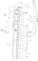
- FIG. 1 1 shows a sliding leaf 2 with a sliding leaf frame 3, on which a sliding leaf driving rail 4 in a U-profile 5 of the sliding leaf frame 3, a ventilation profile 6 and a rosette 8 of a drive device 9 (FIG. Figures 3 . 4 and 5 ) are arranged with a handle 10.
- the fixed frame is 1, its front vertical spar is 1a, see.
- FIGS. 6 The sash 3 has an upright vertical spar 3a. At him the ventilation device is to be arranged.
- the ventilation device has a vertical ventilation profile 6, which is provided with a plurality of ventilation openings, eg many parallel ventilation slots.
- the U-profile 5 and guided therein sliding sash drive rail 4 of the ventilation device can be assigned functionally, but not if the ventilation profile is a retrofit component. It then uses the components 5/4 already present on the sliding sash.
- the ventilation profile 6 of the ventilation device is designed as a separate component and has a ventilation profile-drive rail 7, which is bolted to the sliding leaf drive rail 4 via bolted 12 'stud bolts 12 (in the sense of spacers). Both drive rails 4/7 are displaceable together in the longitudinal direction. Each is guided in the assigned her profile, drive rail 4 the U-profile 5 of the movable wing, drive rail 7 the ventilation profile. 6
- the profiles 6/5 are connected by screws 11. These engage through screw openings 11a, 11b. These are in pairs adjacent to openings 16, 16a for locking pin.
- Corresponding longitudinal slots 6a, 5a are provided in the profiles, along which the stud bolts 12 (with their screw 12 ') are movable, while the drive rails 4, 7, which are coupled by means of these bolts, move in the longitudinal direction (controlled from the drive 9).
- the ventilation profile 6 has as side vents, e.g. Ventilation slots 14 which extend parallel and horizontally on the side webs of the ventilation profile 6 and allow air exchange between the outside and inside of the sash (and the window) when the ventilation device is open.
- side vents e.g. Ventilation slots 14 which extend parallel and horizontally on the side webs of the ventilation profile 6 and allow air exchange between the outside and inside of the sash (and the window) when the ventilation device is open.
- FIG. 1 an opening 16 is shown, through which a locking pin 18 engages, which engages on a bottom 30 of a fixed frame groove 20 (cf. FIGS. 4 ) is to be attached.
- a bolt shoulder (a 18a or one of two lugs 18a, 18b) of the locking pin 18.
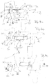
- FIG. 2 shows the embodiment of FIG. 1 in the open (fully released) position of the sliding leaf, wherein the locking pin 18 has come out of the opening 16 after the sliding panel has been moved from the ventilation position to the "open position", which can be seen in the position of the handle 10 (the Screws 11 are present but not shown).
- FIG. 3 shows an exploded view of the U-section 5 and the ventilation profile 6, wherein the drive rails 4.7 are to be connected to each other via the stud bolts 12. This ensures that during a movement of the sliding leaf drive rail. 4 is carried along by the drive device 9, the ventilation profile-drive rail 7, guided in the ventilation profile 6 (at the front, facing the frame bottom).
- the permanently held distance of the drive rails 4/5 corresponds approximately to the height of the long legs of the ventilation profile 6. He is certainly greater than the legs of the U-profile. 5
- FIGS. 4a to 4c each show sections through the fixed frame 22 with a fixed frame leg 23 (corresponds to 1a), in which a Festrahmennut 20 is provided, and the sliding sash frame 3 with the rosette 8 and the handle 10 (the latter in plan view).
- FIG. 4A shows the position of the fixed frame 22 with respect to the sliding sash frame 3 in the position in which the drive rail 7 engages the ventilation profile 6 behind a locking lug 26 of a locking pin 28 (corresponds to 18).
- One or more (short) locking pins 28 are respectively fixed to the bottom 30 of the fixed frame groove 20 and have in the embodiment of FIGS. 4a to 4c only one respective bolt shoulder 26, which is arranged at a distance from the bottom 30 of the fixed frame groove 20, that, as in FIG. 4a is shown, the sliding leaf in the closed position, when the drive rail 7 engages the ventilation profile 6 behind the locking lug 26 of the locking pin 28. An edge of a window is then close to the edge of the vertical spar 1a of the fixed frame.
- the further outboard latches 34 have such a distance from the bottom 30 of the Festrahmennut 20 that, as in FIG. 4b shown, the sliding sash frame 3 is locked in a position in which the ventilation profile 6 between the fixed frame 22 and the sliding sash frame 3 and thus allows an exchange of air through the ventilation openings 14 when the ventilation profile-driving rail 7 engages behind the locking lug 34 of the locking pin 32.
- FIGS. 4 Although in the embodiment of FIGS. 4 two different length locking pins 28 and 32 are shown, and uniform locking pins can be used in which the locking lugs 26 and 34 are combined on a locking pin.
- FIGS. 5a to 5c show a further embodiment, wherein uniform locking pins 36 are each provided with two locking lugs 38, 40 on the same locking pin.
- the locking lug 40 has such a distance from the bottom 30 of the fixed frame groove 20, that the sliding sash frame 3 is in the closed position when the drive rail 4 (of the U-profile) engages behind the locking projection 40.
- the distance between the locking projection 38 and the bottom 30 of the fixed frame groove 20 is dimensioned accordingly.
- FIG. 5c again shows the state in which the fixed frame 20 and the sliding sash frame 3 are completely separated from each other, wherein the ventilation profile 6 protrudes from the sliding sash frame 3 and the pin 36 projects slightly beyond the Festrahmennut 20.
Landscapes
- Engineering & Computer Science (AREA)
- Mechanical Engineering (AREA)
- Civil Engineering (AREA)
- Structural Engineering (AREA)
- Specific Sealing Or Ventilating Devices For Doors And Windows (AREA)
Claims (12)
- Porte coulissante ou fenêtre coulissante équipée d'un vantail coulissant (2) et d'un châssis dormant (22), le vantail coulissant (2) coopérant avec un montant (23) du châssis dormant orienté verticalement sur lequel il s'applique dans sa position de fermeture, un dispositif d'aération comprenant un profilé d'aération (6) réalisé et monté :- de façon à fermer dans une position d'aération du vantail coulissant (2) un espace intermédiaire compris entre ce vantail coulissant (2) et le châssis dormant (22) et pouvant être introduit dans le châssis dormant (22) dans la position de fermeture du vantail coulissant (2),- relié au vantail coulissant (2) et mobile avec celui-ci, le dispositif d'aération comprenant au moins une broche de verrouillage (18, 28, 32, 36) adaptée pour être susceptible de verrouiller le vantail coulissant (2) avec le châssis dormant (22) dans la position d'aération ainsi que dans la position de fermeture du vantail coulissant (2).
- Porte coulissante ou fenêtre coulissante conforme à la revendication 1, comprenant un rail d'entraînement (4) du vantail coulissant (2) pour permettre de verrouiller et de déverrouiller le vantail coulissant (2), le profilé d'aération (6) comprenant un rail d'entraînement (7) qui peut être vissé avec le rail d'entraînement (4) du vantail coulissant en maintenant un écartement (12).
- Porte coulissante ou fenêtre coulissante conforme à la revendication 2, dans laquelle pour permettre de verrouiller le vantail coulissant (2) dans la position d'aération le rail d'entraînement (7) du profilé d'aération est monté, dans la zone avant du profilé d'aération (6).
- Porte coulissante ou fenêtre coulissante conforme à la revendication 1, dans laquelle la broche de verrouillage (18, 28, 32, 36) a une longueur lui permettant d'être ou bord à bord de fermer une rainure (20) prévue sur le châssis dormant (22, 23) pour permettre la réception du profilé d'aération (6) dans la position de fermeture du vantail coulissant (2).
- Porte coulissante ou fenêtre coulissante conforme à la revendication 1, dans laquelle au moins deux broches de verrouillage (28, 32) ont une longueur différente de sorte que des pattes de verrouillage (26, 34) situées sur les broches de verrouillage (28, 32) puissent être à différentes distances d'emplacements de montage au fond (30) de la rainure du châssis dormant (20), en particulier au moins une broche de verrouillage (28) est adaptée pour permettre de bloquer le vantail coulissant (2) avec le châssis dormant (22) dans la position de fermeture de ce vantail coulissant (2) et au moins une broche de verrouillage (32) est adaptée pour permettre de bloquer le vantail coulissant (2) avec le châssis dormant (22) dans la position d'aération de ce vantail coulissant (2).
- Porte coulissante ou fenêtre coulissante conforme à la revendication 1, dans laquelle au moins deux broches de verrouillage (36) ont la même longueur, mais comportent cependant chacune deux pattes de verrouillage (38, 40) et les broches de verrouillage (36) sont adaptés aussi bien pour bloquer le vantail coulissant (2) avec le châssis dormant (22) dans la position de fermeture de ce vantail coulissant (2) et également pour bloquer le vantail coulissant (2) avec le châssis dormant (22) dans la position d'aération de ce vantail coulissant (2).
- Porte coulissante ou fenêtre coulissante conforme à l'une des revendications 1 à 6, dans laquelle le vantail coulissant (2) comporte une garniture qui comporte un dispositif d'entraînement (9) pour un rail d'entraînement (4) du vantail coulissant du dispositif d'aération.
- Porte coulissante ou fenêtre coulissante conforme à l'une des revendications précédentes, dans laquelle le dispositif d'aération qui s'étend longitudinalement comporte un profilé d'aération (6) et un profilé en U (5) pour le vantail coulissant ainsi que deux rails d'entraînement (4, 7) situés à distance ou maintenus à une distance définie (12) et s'étendant parallèlement dans les profilés (5, 6),
le profilé d'aération (6) comprend des ouvertures d'aération (14) le dispositif d'aération comporte au moins une broche de verrouillage (18, 28, 32, 36) adaptée et apte à assurer un blocage avec l'un ou l'autre des rails d'entraînement (4, 7) dans une position d'aération ou dans une position de fermeture (du dispositif d'aération). - Porte coulissante ou fenêtre coulissante conforme à l'une des revendications précédentes, dans laquelle le dispositif d'aération qui s'étend longitudinalement comprend un profilé d'aération (6) et un rail d'entraînement (7) s'étendant dans celui-ci,- ce profilé d'aération (6) comprenant des ouvertures d'aération latérales (14),- le rail d'entraînement mobile (7) étant adapté pour pouvoir être relié en étant écarté par des éléments d'écartement (12) avec un autre rail d'entraînement (4) situé sur le vantail coulissant pour pouvoir être déplacé conjointement dans la direction longitudinale, et le rail d'entraînement mobile (7) étant également conçu et adapté pour pouvoir coopérer avec au moins une broche de verrouillage (18, 28, 32, 36) pour permettre de bloquer le dispositif de verrouillage dans une position d'aération ou dans une position de fermeture.
- Procédé destiné à une porte coulissante ou à une fenêtre coulissante équipée d'un vantail coulissant (2) qui coopère avec un châssis dormant (22) comprenant un montant de châssis dormant (23) orienté verticalement sur lequel le vantail coulissant (2) s'applique dans sa position de fermeture, un dispositif d'aération comprenant un profilé d'aération (6) et au moins une broche de verrouillage,
ce profilé de verrouillage (6) fermant, dans une position d'aération du vantail coulissant un espace intermédiaire situé entre ce vantail coulissant (2) et le montant vertical (23) du châssis dormant (22), et étant introduit dans le montant vertical (23) du châssis dormant (22) dans la position de fermeture du vantail coulissant,
étant relié au vantail coulissant (2) et déplacé avec ce vantail (2), les broches de verrouillage (18, 28, 32, 36) du dispositif d'aération bloquant le vantail coulissant (2) avec le châssis dormant (22) sur son montant vertical (23) dans la position d'aération et également dans la position de fermeture du vantail coulissant. - Procédé conforme à la revendication 10,
caractérisé en ce que
les broches de verrouillage (36) ont la même longueur ne comportent chacune deux pattes de verrouillage (38, 40) et les broches de verrouillage (36) sont adaptées pour bloquer le vantail coulissant (2) avec le châssis dormant (22) dans la position de fermeture du vantail coulissant (2) et également pour bloquer le vantail coulissant (2) avec le châssis dormant (22) dans la position d'aération du vantail coulissant (2). - Procédé conforme à la revendication 10,
selon lequel
lors de la fermeture du vantail coulissant (2) le profilé d'aération (6)- maintenu dans le vantail coulissant - se déplace dans une rainure (20) du montant vertical (23) du châssis dormant (22), de sorte que le profilé (6) ne soit pas visible à l'état fermé du vantail coulissant.
Priority Applications (1)
| Application Number | Priority Date | Filing Date | Title |
|---|---|---|---|
| PL12186905T PL2574716T3 (pl) | 2011-10-01 | 2012-10-01 | Drzwi lub okno przesuwne z urządzeniem wentylacyjnym i sposób pracy |
Applications Claiming Priority (1)
| Application Number | Priority Date | Filing Date | Title |
|---|---|---|---|
| DE102011054130A DE102011054130A1 (de) | 2011-10-01 | 2011-10-01 | Schmale Lüftungsvorrichtung für einen Schiebeflügel |
Publications (3)
| Publication Number | Publication Date |
|---|---|
| EP2574716A2 EP2574716A2 (fr) | 2013-04-03 |
| EP2574716A3 EP2574716A3 (fr) | 2015-02-25 |
| EP2574716B1 true EP2574716B1 (fr) | 2016-03-09 |
Family
ID=47172273
Family Applications (1)
| Application Number | Title | Priority Date | Filing Date |
|---|---|---|---|
| EP12186905.1A Active EP2574716B1 (fr) | 2011-10-01 | 2012-10-01 | Porte ou fenêtre coulissante avec un dispositif d'aération et procédé de travail |
Country Status (3)
| Country | Link |
|---|---|
| EP (1) | EP2574716B1 (fr) |
| DE (1) | DE102011054130A1 (fr) |
| PL (1) | PL2574716T3 (fr) |
Families Citing this family (1)
| Publication number | Priority date | Publication date | Assignee | Title |
|---|---|---|---|---|
| EP2876235A1 (fr) * | 2013-11-21 | 2015-05-27 | Lock Industry Domus Security S.A. | Ensemble de verrouillage pour portes et fenêtres coulissantes |
Family Cites Families (4)
| Publication number | Priority date | Publication date | Assignee | Title |
|---|---|---|---|---|
| DE2061790C3 (de) * | 1970-12-15 | 1979-12-13 | N.V. Metaalindustrie Heycop, Utrecht (Niederlande) | Lüftungsvorrichtung für Fenster, Türen oder dgl |
| GB8507074D0 (en) * | 1985-03-19 | 1985-04-24 | Parkes Josiah & Sons Ltd | Fastening mechanism |
| FR2729177B1 (fr) * | 1995-01-10 | 1997-03-28 | Mandojana Jean Claude | Dispositif de securite a la fermeture pour fenetres, portes et portes-fenetres coulissantes |
| DE202007011762U1 (de) | 2007-08-16 | 2008-12-24 | Gretsch-Unitas GmbH Baubeschläge | Lüftungsvorrichtung |
-
2011
- 2011-10-01 DE DE102011054130A patent/DE102011054130A1/de not_active Withdrawn
-
2012
- 2012-10-01 EP EP12186905.1A patent/EP2574716B1/fr active Active
- 2012-10-01 PL PL12186905T patent/PL2574716T3/pl unknown
Also Published As
| Publication number | Publication date |
|---|---|
| EP2574716A2 (fr) | 2013-04-03 |
| DE102011054130A1 (de) | 2013-04-04 |
| EP2574716A3 (fr) | 2015-02-25 |
| PL2574716T3 (pl) | 2016-08-31 |
Similar Documents
| Publication | Publication Date | Title |
|---|---|---|
| DE69705662T2 (de) | Rollvorrichtung für Schiebetüren, Fenster oder ähnliches | |
| DE102012017948B3 (de) | Verfahren und Anordnung zum Befestigen eines Pfostens an einer Rahmenleiste eines Fensters oder einer Türe mittels eines Pfostenverbinders | |
| DE102017110286A1 (de) | Zarge für einen Schubkasten | |
| DE102016119515A1 (de) | Beschlag für eine Schiebetür, Schiebetüreinheit, Verfahren zum Öffnen einer Schiebetür und Verfahren zum Schließen einer Schiebetür | |
| DE102011011113B4 (de) | Rahmensystem eines Partikelschutzgitters | |
| EP3798390B1 (fr) | Installation de pliage | |
| EP0718456A1 (fr) | Système de fermeture pour fenêtre, porte etc. | |
| EP3859107B1 (fr) | Porte coulissante | |
| EP3045638A1 (fr) | Système de battant coulissant et rotatif | |
| DE102016216835B4 (de) | Aushebesicherung für einen verschiebbaren und zum Verschieben anhebbaren Flügel | |
| EP2574716B1 (fr) | Porte ou fenêtre coulissante avec un dispositif d'aération et procédé de travail | |
| DE29907856U1 (de) | Führungsvorrichtung zur Aufnahme von Gleit- und Schiebeelementen an Möbeln | |
| DE202015100014U1 (de) | Verriegelungsvorrichtung eines beidseitig ausziehbaren Schubladenschrankes | |
| EP3715578B1 (fr) | Porte de protection contre les insectes | |
| DE202007011076U1 (de) | Bandanordnung mit Führungsprofil | |
| DE29917513U1 (de) | Vorrichtung | |
| DE102013017770A1 (de) | Möbel, mit mindestens einem schubladenartigen Ausziehteil | |
| DE102012200430B4 (de) | Schiebetüren- oder -fensteranlage mit mindestens zwei als Tür oder Fenster ausgebildeten Schiebeelementen sowie Verriegelungseinrichtung hierfür | |
| EP3192951B1 (fr) | Ferrure de porte coulissante, porte coulissante, procédé d'ouverture d'une porte coulissante et procédé de fermeture d'une porte coulissante | |
| DE9114374U1 (de) | Treibstangenbeschlag für Fenster, Türen o.dgl. | |
| EP3327228B1 (fr) | Dispositif de verrouillage destiné à verrouiller et à emmener au moins deux éléments en forme de plaque montés en coulissement le long d'une première direction de coulissement et d'une seconde direction de coulissement opposée et système de paroi comprenant au moins deux éléments en forme de plaque | |
| EP3444417B1 (fr) | Système de stockage pour ouvertures de bâtiment | |
| EP2791443B1 (fr) | Meuble avec un dispositif de blocage de sortie pour tiroirs | |
| EP2669462A1 (fr) | Dispositif de retenue pour stores à lamelles contractées | |
| DE202013004939U1 (de) | Vorrichtung zur Positionierung und Fixierung eines beweglichen Möbelteils |
Legal Events
| Date | Code | Title | Description |
|---|---|---|---|
| PUAI | Public reference made under article 153(3) epc to a published international application that has entered the european phase |
Free format text: ORIGINAL CODE: 0009012 |
|
| AK | Designated contracting states |
Kind code of ref document: A2 Designated state(s): AL AT BE BG CH CY CZ DE DK EE ES FI FR GB GR HR HU IE IS IT LI LT LU LV MC MK MT NL NO PL PT RO RS SE SI SK SM TR |
|
| AX | Request for extension of the european patent |
Extension state: BA ME |
|
| PUAL | Search report despatched |
Free format text: ORIGINAL CODE: 0009013 |
|
| AK | Designated contracting states |
Kind code of ref document: A3 Designated state(s): AL AT BE BG CH CY CZ DE DK EE ES FI FR GB GR HR HU IE IS IT LI LT LU LV MC MK MT NL NO PL PT RO RS SE SI SK SM TR |
|
| AX | Request for extension of the european patent |
Extension state: BA ME |
|
| RIC1 | Information provided on ipc code assigned before grant |
Ipc: E05B 65/08 20060101ALI20150116BHEP Ipc: E06B 7/02 20060101AFI20150116BHEP |
|
| 17P | Request for examination filed |
Effective date: 20150428 |
|
| RBV | Designated contracting states (corrected) |
Designated state(s): AL AT BE BG CH CY CZ DE DK EE ES FI FR GB GR HR HU IE IS IT LI LT LU LV MC MK MT NL NO PL PT RO RS SE SI SK SM TR |
|
| GRAP | Despatch of communication of intention to grant a patent |
Free format text: ORIGINAL CODE: EPIDOSNIGR1 |
|
| INTG | Intention to grant announced |
Effective date: 20151022 |
|
| GRAS | Grant fee paid |
Free format text: ORIGINAL CODE: EPIDOSNIGR3 |
|
| GRAA | (expected) grant |
Free format text: ORIGINAL CODE: 0009210 |
|
| AK | Designated contracting states |
Kind code of ref document: B1 Designated state(s): AL AT BE BG CH CY CZ DE DK EE ES FI FR GB GR HR HU IE IS IT LI LT LU LV MC MK MT NL NO PL PT RO RS SE SI SK SM TR |
|
| REG | Reference to a national code |
Ref country code: GB Ref legal event code: FG4D Free format text: NOT ENGLISH |
|
| REG | Reference to a national code |
Ref country code: AT Ref legal event code: REF Ref document number: 779685 Country of ref document: AT Kind code of ref document: T Effective date: 20160315 Ref country code: CH Ref legal event code: EP |
|
| REG | Reference to a national code |
Ref country code: IE Ref legal event code: FG4D Free format text: LANGUAGE OF EP DOCUMENT: GERMAN |
|
| REG | Reference to a national code |
Ref country code: CH Ref legal event code: NV Representative=s name: ISLER AND PEDRAZZINI AG, CH |
|
| REG | Reference to a national code |
Ref country code: DE Ref legal event code: R096 Ref document number: 502012006209 Country of ref document: DE |
|
| REG | Reference to a national code |
Ref country code: NL Ref legal event code: FP |
|
| REG | Reference to a national code |
Ref country code: LT Ref legal event code: MG4D |
|
| PG25 | Lapsed in a contracting state [announced via postgrant information from national office to epo] |
Ref country code: FI Free format text: LAPSE BECAUSE OF FAILURE TO SUBMIT A TRANSLATION OF THE DESCRIPTION OR TO PAY THE FEE WITHIN THE PRESCRIBED TIME-LIMIT Effective date: 20160309 Ref country code: NO Free format text: LAPSE BECAUSE OF FAILURE TO SUBMIT A TRANSLATION OF THE DESCRIPTION OR TO PAY THE FEE WITHIN THE PRESCRIBED TIME-LIMIT Effective date: 20160609 Ref country code: HR Free format text: LAPSE BECAUSE OF FAILURE TO SUBMIT A TRANSLATION OF THE DESCRIPTION OR TO PAY THE FEE WITHIN THE PRESCRIBED TIME-LIMIT Effective date: 20160309 Ref country code: ES Free format text: LAPSE BECAUSE OF FAILURE TO SUBMIT A TRANSLATION OF THE DESCRIPTION OR TO PAY THE FEE WITHIN THE PRESCRIBED TIME-LIMIT Effective date: 20160309 Ref country code: GR Free format text: LAPSE BECAUSE OF FAILURE TO SUBMIT A TRANSLATION OF THE DESCRIPTION OR TO PAY THE FEE WITHIN THE PRESCRIBED TIME-LIMIT Effective date: 20160610 |
|
| PG25 | Lapsed in a contracting state [announced via postgrant information from national office to epo] |
Ref country code: RS Free format text: LAPSE BECAUSE OF FAILURE TO SUBMIT A TRANSLATION OF THE DESCRIPTION OR TO PAY THE FEE WITHIN THE PRESCRIBED TIME-LIMIT Effective date: 20160309 Ref country code: SE Free format text: LAPSE BECAUSE OF FAILURE TO SUBMIT A TRANSLATION OF THE DESCRIPTION OR TO PAY THE FEE WITHIN THE PRESCRIBED TIME-LIMIT Effective date: 20160309 Ref country code: LT Free format text: LAPSE BECAUSE OF FAILURE TO SUBMIT A TRANSLATION OF THE DESCRIPTION OR TO PAY THE FEE WITHIN THE PRESCRIBED TIME-LIMIT Effective date: 20160309 Ref country code: LV Free format text: LAPSE BECAUSE OF FAILURE TO SUBMIT A TRANSLATION OF THE DESCRIPTION OR TO PAY THE FEE WITHIN THE PRESCRIBED TIME-LIMIT Effective date: 20160309 |
|
| PG25 | Lapsed in a contracting state [announced via postgrant information from national office to epo] |
Ref country code: IS Free format text: LAPSE BECAUSE OF FAILURE TO SUBMIT A TRANSLATION OF THE DESCRIPTION OR TO PAY THE FEE WITHIN THE PRESCRIBED TIME-LIMIT Effective date: 20160709 Ref country code: EE Free format text: LAPSE BECAUSE OF FAILURE TO SUBMIT A TRANSLATION OF THE DESCRIPTION OR TO PAY THE FEE WITHIN THE PRESCRIBED TIME-LIMIT Effective date: 20160309 |
|
| PG25 | Lapsed in a contracting state [announced via postgrant information from national office to epo] |
Ref country code: SK Free format text: LAPSE BECAUSE OF FAILURE TO SUBMIT A TRANSLATION OF THE DESCRIPTION OR TO PAY THE FEE WITHIN THE PRESCRIBED TIME-LIMIT Effective date: 20160309 Ref country code: CZ Free format text: LAPSE BECAUSE OF FAILURE TO SUBMIT A TRANSLATION OF THE DESCRIPTION OR TO PAY THE FEE WITHIN THE PRESCRIBED TIME-LIMIT Effective date: 20160309 Ref country code: RO Free format text: LAPSE BECAUSE OF FAILURE TO SUBMIT A TRANSLATION OF THE DESCRIPTION OR TO PAY THE FEE WITHIN THE PRESCRIBED TIME-LIMIT Effective date: 20160309 Ref country code: SM Free format text: LAPSE BECAUSE OF FAILURE TO SUBMIT A TRANSLATION OF THE DESCRIPTION OR TO PAY THE FEE WITHIN THE PRESCRIBED TIME-LIMIT Effective date: 20160309 Ref country code: PT Free format text: LAPSE BECAUSE OF FAILURE TO SUBMIT A TRANSLATION OF THE DESCRIPTION OR TO PAY THE FEE WITHIN THE PRESCRIBED TIME-LIMIT Effective date: 20160711 |
|
| REG | Reference to a national code |
Ref country code: DE Ref legal event code: R097 Ref document number: 502012006209 Country of ref document: DE |
|
| PLBE | No opposition filed within time limit |
Free format text: ORIGINAL CODE: 0009261 |
|
| STAA | Information on the status of an ep patent application or granted ep patent |
Free format text: STATUS: NO OPPOSITION FILED WITHIN TIME LIMIT |
|
| PG25 | Lapsed in a contracting state [announced via postgrant information from national office to epo] |
Ref country code: DK Free format text: LAPSE BECAUSE OF FAILURE TO SUBMIT A TRANSLATION OF THE DESCRIPTION OR TO PAY THE FEE WITHIN THE PRESCRIBED TIME-LIMIT Effective date: 20160309 |
|
| 26N | No opposition filed |
Effective date: 20161212 |
|
| PG25 | Lapsed in a contracting state [announced via postgrant information from national office to epo] |
Ref country code: BG Free format text: LAPSE BECAUSE OF FAILURE TO SUBMIT A TRANSLATION OF THE DESCRIPTION OR TO PAY THE FEE WITHIN THE PRESCRIBED TIME-LIMIT Effective date: 20160609 |
|
| PG25 | Lapsed in a contracting state [announced via postgrant information from national office to epo] |
Ref country code: SI Free format text: LAPSE BECAUSE OF FAILURE TO SUBMIT A TRANSLATION OF THE DESCRIPTION OR TO PAY THE FEE WITHIN THE PRESCRIBED TIME-LIMIT Effective date: 20160309 |
|
| GBPC | Gb: european patent ceased through non-payment of renewal fee |
Effective date: 20161001 |
|
| REG | Reference to a national code |
Ref country code: IE Ref legal event code: MM4A |
|
| REG | Reference to a national code |
Ref country code: FR Ref legal event code: ST Effective date: 20170630 |
|
| PG25 | Lapsed in a contracting state [announced via postgrant information from national office to epo] |
Ref country code: FR Free format text: LAPSE BECAUSE OF NON-PAYMENT OF DUE FEES Effective date: 20161102 Ref country code: GB Free format text: LAPSE BECAUSE OF NON-PAYMENT OF DUE FEES Effective date: 20161001 |
|
| PG25 | Lapsed in a contracting state [announced via postgrant information from national office to epo] |
Ref country code: LU Free format text: LAPSE BECAUSE OF NON-PAYMENT OF DUE FEES Effective date: 20161001 |
|
| PG25 | Lapsed in a contracting state [announced via postgrant information from national office to epo] |
Ref country code: IE Free format text: LAPSE BECAUSE OF NON-PAYMENT OF DUE FEES Effective date: 20161001 |
|
| PGFP | Annual fee paid to national office [announced via postgrant information from national office to epo] |
Ref country code: BE Payment date: 20171023 Year of fee payment: 6 Ref country code: NL Payment date: 20171023 Year of fee payment: 6 Ref country code: CH Payment date: 20171023 Year of fee payment: 6 Ref country code: AT Payment date: 20171018 Year of fee payment: 6 |
|
| PG25 | Lapsed in a contracting state [announced via postgrant information from national office to epo] |
Ref country code: CY Free format text: LAPSE BECAUSE OF FAILURE TO SUBMIT A TRANSLATION OF THE DESCRIPTION OR TO PAY THE FEE WITHIN THE PRESCRIBED TIME-LIMIT Effective date: 20160309 Ref country code: HU Free format text: LAPSE BECAUSE OF FAILURE TO SUBMIT A TRANSLATION OF THE DESCRIPTION OR TO PAY THE FEE WITHIN THE PRESCRIBED TIME-LIMIT; INVALID AB INITIO Effective date: 20121001 |
|
| PG25 | Lapsed in a contracting state [announced via postgrant information from national office to epo] |
Ref country code: MT Free format text: LAPSE BECAUSE OF FAILURE TO SUBMIT A TRANSLATION OF THE DESCRIPTION OR TO PAY THE FEE WITHIN THE PRESCRIBED TIME-LIMIT Effective date: 20160309 Ref country code: TR Free format text: LAPSE BECAUSE OF FAILURE TO SUBMIT A TRANSLATION OF THE DESCRIPTION OR TO PAY THE FEE WITHIN THE PRESCRIBED TIME-LIMIT Effective date: 20160309 Ref country code: MC Free format text: LAPSE BECAUSE OF FAILURE TO SUBMIT A TRANSLATION OF THE DESCRIPTION OR TO PAY THE FEE WITHIN THE PRESCRIBED TIME-LIMIT Effective date: 20160309 Ref country code: MK Free format text: LAPSE BECAUSE OF FAILURE TO SUBMIT A TRANSLATION OF THE DESCRIPTION OR TO PAY THE FEE WITHIN THE PRESCRIBED TIME-LIMIT Effective date: 20160309 |
|
| PG25 | Lapsed in a contracting state [announced via postgrant information from national office to epo] |
Ref country code: AL Free format text: LAPSE BECAUSE OF FAILURE TO SUBMIT A TRANSLATION OF THE DESCRIPTION OR TO PAY THE FEE WITHIN THE PRESCRIBED TIME-LIMIT Effective date: 20160309 |
|
| PGFP | Annual fee paid to national office [announced via postgrant information from national office to epo] |
Ref country code: PL Payment date: 20180913 Year of fee payment: 7 |
|
| PGFP | Annual fee paid to national office [announced via postgrant information from national office to epo] |
Ref country code: IT Payment date: 20181022 Year of fee payment: 7 |
|
| REG | Reference to a national code |
Ref country code: CH Ref legal event code: PL |
|
| REG | Reference to a national code |
Ref country code: NL Ref legal event code: MM Effective date: 20181101 |
|
| REG | Reference to a national code |
Ref country code: AT Ref legal event code: MM01 Ref document number: 779685 Country of ref document: AT Kind code of ref document: T Effective date: 20181001 |
|
| REG | Reference to a national code |
Ref country code: BE Ref legal event code: MM Effective date: 20181031 |
|
| PG25 | Lapsed in a contracting state [announced via postgrant information from national office to epo] |
Ref country code: NL Free format text: LAPSE BECAUSE OF NON-PAYMENT OF DUE FEES Effective date: 20181101 |
|
| PG25 | Lapsed in a contracting state [announced via postgrant information from national office to epo] |
Ref country code: LI Free format text: LAPSE BECAUSE OF NON-PAYMENT OF DUE FEES Effective date: 20181031 Ref country code: BE Free format text: LAPSE BECAUSE OF NON-PAYMENT OF DUE FEES Effective date: 20181031 Ref country code: CH Free format text: LAPSE BECAUSE OF NON-PAYMENT OF DUE FEES Effective date: 20181031 |
|
| PG25 | Lapsed in a contracting state [announced via postgrant information from national office to epo] |
Ref country code: AT Free format text: LAPSE BECAUSE OF NON-PAYMENT OF DUE FEES Effective date: 20181001 |
|
| PG25 | Lapsed in a contracting state [announced via postgrant information from national office to epo] |
Ref country code: IT Free format text: LAPSE BECAUSE OF NON-PAYMENT OF DUE FEES Effective date: 20191001 |
|
| PG25 | Lapsed in a contracting state [announced via postgrant information from national office to epo] |
Ref country code: PL Free format text: LAPSE BECAUSE OF NON-PAYMENT OF DUE FEES Effective date: 20191001 |
|
| PGFP | Annual fee paid to national office [announced via postgrant information from national office to epo] |
Ref country code: DE Payment date: 20240126 Year of fee payment: 13 |