EP2574724A2 - Ensemble empilé de rotor de moteur à turbine à gaz, moteur à turbine à gaz et procédé de fabrication associés - Google Patents
Ensemble empilé de rotor de moteur à turbine à gaz, moteur à turbine à gaz et procédé de fabrication associés Download PDFInfo
- Publication number
- EP2574724A2 EP2574724A2 EP12186435A EP12186435A EP2574724A2 EP 2574724 A2 EP2574724 A2 EP 2574724A2 EP 12186435 A EP12186435 A EP 12186435A EP 12186435 A EP12186435 A EP 12186435A EP 2574724 A2 EP2574724 A2 EP 2574724A2
- Authority
- EP
- European Patent Office
- Prior art keywords
- rotor assembly
- rotor
- assembly
- rim
- load path
- Prior art date
- Legal status (The legal status is an assumption and is not a legal conclusion. Google has not performed a legal analysis and makes no representation as to the accuracy of the status listed.)
- Granted
Links
- 238000004519 manufacturing process Methods 0.000 title 1
- 238000000034 method Methods 0.000 claims abstract description 6
- 125000006850 spacer group Chemical group 0.000 claims description 5
- 238000011144 upstream manufacturing Methods 0.000 claims 1
- 239000007789 gas Substances 0.000 description 34
- 230000000712 assembly Effects 0.000 description 15
- 238000000429 assembly Methods 0.000 description 15
- 239000000567 combustion gas Substances 0.000 description 4
- 230000006835 compression Effects 0.000 description 2
- 238000007906 compression Methods 0.000 description 2
- 239000000446 fuel Substances 0.000 description 2
- 230000007246 mechanism Effects 0.000 description 2
- 238000004891 communication Methods 0.000 description 1
- 230000001143 conditioned effect Effects 0.000 description 1
- 238000010276 construction Methods 0.000 description 1
- 239000000284 extract Substances 0.000 description 1
- 238000012986 modification Methods 0.000 description 1
- 230000004048 modification Effects 0.000 description 1
- 238000007789 sealing Methods 0.000 description 1
- 230000003068 static effect Effects 0.000 description 1
Images


Classifications
-
- F—MECHANICAL ENGINEERING; LIGHTING; HEATING; WEAPONS; BLASTING
- F01—MACHINES OR ENGINES IN GENERAL; ENGINE PLANTS IN GENERAL; STEAM ENGINES
- F01D—NON-POSITIVE DISPLACEMENT MACHINES OR ENGINES, e.g. STEAM TURBINES
- F01D5/00—Blades; Blade-carrying members; Heating, heat-insulating, cooling or antivibration means on the blades or the members
- F01D5/02—Blade-carrying members, e.g. rotors
- F01D5/06—Rotors for more than one axial stage, e.g. of drum or multiple disc type; Details thereof, e.g. shafts, shaft connections
- F01D5/066—Connecting means for joining rotor-discs or rotor-elements together, e.g. by a central bolt, by clamps
-
- F—MECHANICAL ENGINEERING; LIGHTING; HEATING; WEAPONS; BLASTING
- F01—MACHINES OR ENGINES IN GENERAL; ENGINE PLANTS IN GENERAL; STEAM ENGINES
- F01D—NON-POSITIVE DISPLACEMENT MACHINES OR ENGINES, e.g. STEAM TURBINES
- F01D11/00—Preventing or minimising internal leakage of working-fluid, e.g. between stages
- F01D11/001—Preventing or minimising internal leakage of working-fluid, e.g. between stages for sealing space between stator blade and rotor
-
- Y—GENERAL TAGGING OF NEW TECHNOLOGICAL DEVELOPMENTS; GENERAL TAGGING OF CROSS-SECTIONAL TECHNOLOGIES SPANNING OVER SEVERAL SECTIONS OF THE IPC; TECHNICAL SUBJECTS COVERED BY FORMER USPC CROSS-REFERENCE ART COLLECTIONS [XRACs] AND DIGESTS
- Y10—TECHNICAL SUBJECTS COVERED BY FORMER USPC
- Y10T—TECHNICAL SUBJECTS COVERED BY FORMER US CLASSIFICATION
- Y10T29/00—Metal working
- Y10T29/49—Method of mechanical manufacture
- Y10T29/49316—Impeller making
- Y10T29/4932—Turbomachine making
Definitions
- This disclosure relates to a gas turbine engine, and more particularly to a rotor stack assembly for a gas turbine engine.
- Gas turbine engines typically include at least a compressor section, a combustor section and a turbine section. During operation, air is pressurized in the compressor section and mixed with fuel and burned in the combustor section to generate hot combustion gases. The hot combustion gases are communicated through the turbine section which extracts energy from the hot combustion gases to power the compressor section and other gas turbine engine loads.
- One or more sections of the gas turbine engine may include a rotor stack assembly having a plurality of rotor assemblies that carry the airfoils or blades of successive stages of the section.
- a stator assembly is interspersed between each rotor assembly.
- the rotor assemblies of the rotor stack assembly can be held in compression in a variety of ways, including by using a tie shaft.
- a rotor stack assembly for a gas turbine engine includes a first rotor assembly and a second rotor assembly axially downstream from the first rotor assembly.
- the first rotor assembly includes a first rim, a first bore and a first web that extends between the first rim and the first bore.
- the second rotor assembly includes a second rim, a second bore and a second web that extends between the second rim and the second bore.
- a tie shaft is positioned radially inward of the first bore and the second bore. The tie shaft maintains a compressive load on the first rotor assembly and the second rotor assembly. The compressive load is communicated through a first load path of the first rotor assembly and a second load path of the second rotor assembly. At least one of the first load path and the second load path is radially inboard of the first rim and the second rim.
- a gas turbine engine in another exemplary embodiment, includes a compressor section, a combustor section and a turbine section each disposed about an engine centerline axis.
- a rotor stack assembly is disposed within at least one of the compressor section and the turbine section.
- the rotor stack assembly includes at least a first rotor assembly and a second rotor assembly downstream from the first rotor assembly.
- a tie shaft is positioned radially inward of the first rotor assembly and the second rotor assembly and maintains a compressive load on the first rotor assembly and the second rotor assembly.
- the compressive load is communicated through the first rotor assembly along a first load path and through the second rotor assembly along a second load path.
- the first rotor assembly includes a first radial gap establishing a first distance between a first rim and the first load path of the first rotor assembly and the second rotor assembly includes a second radial gap establishing a second distance between a second rim and the second load path of the second rotor assembly.
- the second distance is greater than the first distance.
- a method for providing a rotor stack assembly for a gas turbine engine includes lowering a load path of a rotor assembly of the rotor stack assembly. A rim of the rotor assembly is isolated from a primary gas path of the gas turbine engine.
- FIG. 1 schematically illustrates a gas turbine engine 10.
- the example gas turbine engine 10 is a two spool turbofan engine that generally incorporates a fan section 14, a compressor section 16, a combustor section 18 and a turbine section 20.
- Alternative engines might include fewer or additional sections such as an augmenter section (not shown) among other systems or features.
- the fan section 14 drives air along a bypass flow path
- the compressor section 16 drives air along a core flow path for compression and communication into the combustor section 18.
- the hot combustion gases generated in the combustor section 18 are expanded through the turbine section 20.
- This view is highly schematic and is included to provide a basic understanding of the gas turbine engine 10 and not to limit the disclosure. This disclosure extends to all types of gas turbine engines and to all types of applications.
- the gas turbine engine 10 generally includes at least a low speed spool 22 and a high speed spool 24 mounted for rotation about an engine centerline axis 12 relative to an engine static structure 27 via several bearing systems 29.
- the low speed spool 22 generally includes an inner shaft 31 that interconnects a fan 33, a low pressure compressor 17, and a low pressure turbine 21.
- the inner shaft 31 can connect to the fan 33 through a geared architecture 35 to drive the fan 33 at a lower speed than the low speed spool 22.
- the high speed spool 24 includes an outer shaft 37 that interconnects a high pressure compressor 19 and a high pressure turbine 23.
- a combustor 15 is arranged between the high pressure compressor 19 and the high pressure turbine 23.
- the inner shaft 31 and the outer shaft 37 are concentric and rotate about the engine centerline axis 12.
- a core airflow is compressed by the low pressure compressor 17 and the high pressure compressor 19, is mixed with fuel and burned within the combustor 15, and is then expanded over the high pressure turbine 23 and the low pressure turbine 21.
- the turbines 21, 23 rotationally drive the low speed spool 22 and the high speed spool 24 in response to the expansion.
- Figure 2 illustrates a portion 100 of a gas turbine engine 10.
- the illustrated portion is the high pressure compressor 19 of the gas turbine engine 10.
- this disclosure is not limited to the high pressure compressor 19, and could extend to other sections of the gas turbine engine 10.
- the portion 100 of the gas turbine engine 10 includes a rotor stack assembly 25.
- the rotor stack assembly 25 is composed of a plurality of rotor assemblies 26 that are circumferentially disposed about the engine centerline axis 12. Vane assemblies 30 having at least one stator vane 32 are interspersed axially between the rotor assemblies 26.
- the portion 100 could include fewer or additional stages.
- Each rotor assembly 26 includes one or more rotor airfoils (or blades) 28 and a rotor disk 36.
- the rotor disks 36 carry the rotor airfoils 28 and are rotatable about the engine centerline axis 12 to rotate the rotor airfoils 28.
- Each rotor disk 36 includes a rim 38, a bore 40 and a web 42 that extends between the rim 38 and the bore 40.
- a plurality of cavities 44 extend between adjacent rotor disks 36. The cavities 44 are radially inward from the airfoils 28 and the stator vanes 32.
- a plurality of spacers 45 can extend between adjacent rotor disks 36. The plurality of spacers 45 can include sealing mechanisms 55 that seal the cavities 44 as well as the inner diameters of the stator vanes 32.
- a primary gas path 46 for directing a stream of core airflow axially in an annular flow is generally defined by the multiples stages of rotor assemblies 26 and the vane assemblies 30. Each stage of the portion 100 includes one rotor assembly 26 and one vane assembly 30.
- the primary gas path 46 extends radially between an inner wall 48 of an engine casing 53 and the rims 38 of the rotor disks 36, as well as inner platforms 51 of the vane assemblies 30.
- the temperature of the primary gas path 46 generally increases as the primary gas path is communicated downstream (i.e., the temperature increases in each successive stage of the portion 100).
- the rotor stack assembly 25 can also define a secondary gas path that is generally radially inward from the primary gas path 46.
- a conditioned airflow such as a cooled, heated or pressurized airflow, can be communicated through the secondary gas path to condition specific areas of the rotor stack assembly 25, such as the rotor assemblies 26.
- a tie shaft 47 extends through the rotor stack assembly 25 on a radially inner side of the bores 40.
- the tie shaft 47 can be preloaded to maintain a compressive load on the rotor assemblies 26 of the rotor stack assembly 25.
- the tie shaft 47 extends between a forward hub 49 and an aft hub 50.
- the tie shaft 47 can be threaded through the forward hub 49 and snapped into the rotor disk 36 of the final stage of the portion 100. Once connected between the forward hub 49 and the aft hub 50, the preloaded tension on the tie shaft 47 can be maintained by a nut or other mechanisms.
- the tie shaft 47 maintains a compressive load on the rotor stack assembly 25.
- the compressive load is communicated along a load path that extends through the "backbone" of the rotor stack assembly 25.
- the load path is indicated by the solid line LP of Figure 2 , and can be communicated through the spacers 45 that extend between adjacent rotor disks 36.
- a radial gap 60 extends between the rims 38 and the load path LP of each rotor disk 36.
- the load paths of at least a portion of the rotor disks 36 of the rotor stack assembly 25 are radially inboard from the rims 38 of the rotor assemblies 26, as is further discussed below. That is, the load path is generally lowered through at least a portion of the rotor stack assembly 25.
- the rotor assemblies 26 positioned in at least an aft portion 102 of the rotor stack assembly 25 can be bladed rotor assemblies, as is also discussed in greater detail below.
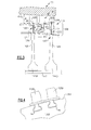
- Figure 3 illustrates an exemplary rotor stack assembly 125 having a first rotor assembly 126A and a second rotor assembly 126B that is positioned axially downstream (i.e., aft) from the first rotor assembly 126A.
- aft axially downstream
- the first rotor assembly 126A includes a first rotor airfoil 128A and a first rotor disk 136A including a first rim 138A, a first bore 140A and a first web 142A that extends between the first rim 138A and the first bore 140A.
- the second rotor assembly 126B includes a first rotor airfoil 128B and a second rotor disk 136B that includes a second rim 138B, a second bore 140B and a second web 142B that extends between the second rim 138B and the second bore 140B.
- the first rotor assembly 126A includes integrally bladed airfoils 128A of a single-piece construction (i.e., monolithic structures) and the second rotor assembly 126B includes airfoils 128B that are bladed (i.e., the airfoils 128B are separate structures from the second rotor disk 136B).
- the airfoils 128B of the second rotor assembly 126B can be received and carried by a plurality of slots 90 that extend through the rim 138B of the second rotor assembly 126B (See Figure 4 ).
- the second rim 138B of the second rotor assembly 126B is substantially isolated from the primary gas path 46, i.e., the second rim 138B is positioned below, or radially inward, relative to the interface between the slots 90 and the airfoils 128B.
- a tie shaft 147 maintains a compressive load through the first rotor assembly 126A and the second rotors assembly 126B.
- This compressive load is communicated through a first load path LP 1 of the first rotor assembly 126A and a second load path LP2 of the second rotor assembly 126B.
- the first load path LP1 and second load path LP2 are radially inboard from the rims 138A and 138B, respectively.
- the load paths LP1 and LP2 extend through a portion of the webs 142A, 142B, in this example.
- a first radial gap 160A establishes a first distance D1 between the first rim 138A and the first load path LP1.
- a second radial gap 160B similarly establishes a second distance D2 between the second rim 138B and the second load path LP2.
- the second distance D2 is a greater distance than the first distance D1. Therefore, the second load path LP2 of the second rotor assembly 126B extends radially inboard from the first load path LP1 of the first rotor assembly 126A.
- the rim 138B of the second rotor assembly 126B is therefore substantially thermally isolated from the primary gas path 46, thereby improving thermal mechanical fatigue characteristics of the rotor assembly 126B.
- the second rotor assembly 126B of this example is illustrated as rotor assembly of the final stage of the portion 100 of the gas turbine engine 10.
- a rotor assembly having a lowered load path such as illustrated by the rotor assembly 126B can be provided in additional stages of the portion 100.
- the final two stages (or additional stages) of the high pressure compressor 19 of the gas turbine engine 10 can include a rotor assembly having a reduced load path (see Figure 2 ).
- the radial gap associated with each rotor assembly 126A, 126B (in at least the portion 100 of the gas turbine engine 10) can increase as the temperature increases with each successive stage of the rotor stack assembly 125 in the primary gas path 46.
Landscapes
- Engineering & Computer Science (AREA)
- Mechanical Engineering (AREA)
- General Engineering & Computer Science (AREA)
- Structures Of Non-Positive Displacement Pumps (AREA)
- Turbine Rotor Nozzle Sealing (AREA)
Applications Claiming Priority (1)
| Application Number | Priority Date | Filing Date | Title |
|---|---|---|---|
| US13/248,350 US10077663B2 (en) | 2011-09-29 | 2011-09-29 | Gas turbine engine rotor stack assembly |
Publications (3)
| Publication Number | Publication Date |
|---|---|
| EP2574724A2 true EP2574724A2 (fr) | 2013-04-03 |
| EP2574724A3 EP2574724A3 (fr) | 2015-09-02 |
| EP2574724B1 EP2574724B1 (fr) | 2018-04-25 |
Family
ID=46940403
Family Applications (1)
| Application Number | Title | Priority Date | Filing Date |
|---|---|---|---|
| EP12186435.9A Active EP2574724B1 (fr) | 2011-09-29 | 2012-09-27 | Ensemble de rotor de moteur à turbine à gaz |
Country Status (2)
| Country | Link |
|---|---|
| US (1) | US10077663B2 (fr) |
| EP (1) | EP2574724B1 (fr) |
Cited By (1)
| Publication number | Priority date | Publication date | Assignee | Title |
|---|---|---|---|---|
| FR3002586A1 (fr) * | 2013-02-28 | 2014-08-29 | Snecma | Reduction des echanges convectifs entre l'air et le rotor dans une turbine |
Families Citing this family (10)
| Publication number | Priority date | Publication date | Assignee | Title |
|---|---|---|---|---|
| US8784062B2 (en) * | 2011-10-28 | 2014-07-22 | United Technologies Corporation | Asymmetrically slotted rotor for a gas turbine engine |
| EP3004564A4 (fr) * | 2013-06-07 | 2016-11-23 | Ge Aviat Systems Llc | Réacteur à double flux équipé d'un générateur |
| US9896938B2 (en) | 2015-02-05 | 2018-02-20 | Honeywell International Inc. | Gas turbine engines with internally stretched tie shafts |
| US10584599B2 (en) * | 2017-07-14 | 2020-03-10 | United Technologies Corporation | Compressor rotor stack assembly for gas turbine engine |
| ES2828719T3 (es) * | 2017-11-09 | 2021-05-27 | MTU Aero Engines AG | Disposición de sellado para una turbomáquina, método para la fabricación de una disposición de sellado y turbomáquina |
| US10644630B2 (en) | 2017-11-28 | 2020-05-05 | General Electric Company | Turbomachine with an electric machine assembly and method for operation |
| US10876429B2 (en) | 2019-03-21 | 2020-12-29 | Pratt & Whitney Canada Corp. | Shroud segment assembly intersegment end gaps control |
| US11525400B2 (en) | 2020-07-08 | 2022-12-13 | General Electric Company | System for rotor assembly thermal gradient reduction |
| US12480449B2 (en) | 2022-08-22 | 2025-11-25 | General Electric Company | Propulsion system including an electric machine for starting a gas turbine engine |
| US12247580B2 (en) * | 2023-05-03 | 2025-03-11 | General Electric Company | Forward load reduction structures for aft-most stages of high pressure compressors |
Family Cites Families (17)
| Publication number | Priority date | Publication date | Assignee | Title |
|---|---|---|---|---|
| US2213940A (en) | 1937-07-07 | 1940-09-03 | Jendrassik George | Rotor for gas turbines and rotary compressors |
| US2458149A (en) | 1944-08-23 | 1949-01-04 | United Aircraft Corp | Rotor construction for turbines |
| US2452782A (en) | 1945-01-16 | 1948-11-02 | Power Jets Res & Dev Ltd | Construction of rotors for compressors and like machines |
| US2675174A (en) * | 1950-05-11 | 1954-04-13 | Gen Motors Corp | Turbine or compressor rotor |
| GB1349170A (en) | 1970-07-09 | 1974-03-27 | Kraftwerk Union Ag | Rotor for a gas turbine engine |
| US5232339A (en) | 1992-01-28 | 1993-08-03 | General Electric Company | Finned structural disk spacer arm |
| US5537814A (en) * | 1994-09-28 | 1996-07-23 | General Electric Company | High pressure gas generator rotor tie rod system for gas turbine engine |
| US6267553B1 (en) | 1999-06-01 | 2001-07-31 | Joseph C. Burge | Gas turbine compressor spool with structural and thermal upgrades |
| US6511294B1 (en) | 1999-09-23 | 2003-01-28 | General Electric Company | Reduced-stress compressor blisk flowpath |
| US6471474B1 (en) * | 2000-10-20 | 2002-10-29 | General Electric Company | Method and apparatus for reducing rotor assembly circumferential rim stress |
| US6588317B2 (en) * | 2001-11-09 | 2003-07-08 | Delphi Technologies, Inc. | Power booster sealing mechanism |
| US7059831B2 (en) * | 2004-04-15 | 2006-06-13 | United Technologies Corporation | Turbine engine disk spacers |
| US7448221B2 (en) | 2004-12-17 | 2008-11-11 | United Technologies Corporation | Turbine engine rotor stack |
| DE102008008887A1 (de) * | 2008-02-13 | 2009-08-27 | Man Turbo Ag | Mehrteiliger beschaufelter Rotor für eine Strömungsmaschine |
| US8287242B2 (en) * | 2008-11-17 | 2012-10-16 | United Technologies Corporation | Turbine engine rotor hub |
| US8517687B2 (en) | 2010-03-10 | 2013-08-27 | United Technologies Corporation | Gas turbine engine compressor and turbine section assembly utilizing tie shaft |
| US8550784B2 (en) * | 2011-05-04 | 2013-10-08 | United Technologies Corporation | Gas turbine engine rotor construction |
-
2011
- 2011-09-29 US US13/248,350 patent/US10077663B2/en active Active
-
2012
- 2012-09-27 EP EP12186435.9A patent/EP2574724B1/fr active Active
Non-Patent Citations (1)
| Title |
|---|
| None |
Cited By (2)
| Publication number | Priority date | Publication date | Assignee | Title |
|---|---|---|---|---|
| FR3002586A1 (fr) * | 2013-02-28 | 2014-08-29 | Snecma | Reduction des echanges convectifs entre l'air et le rotor dans une turbine |
| WO2014132001A1 (fr) | 2013-02-28 | 2014-09-04 | Snecma | Réduction des échanges convectifs entre l'air et le rotor dans une turbine |
Also Published As
| Publication number | Publication date |
|---|---|
| EP2574724B1 (fr) | 2018-04-25 |
| EP2574724A3 (fr) | 2015-09-02 |
| US20130081406A1 (en) | 2013-04-04 |
| US10077663B2 (en) | 2018-09-18 |
Similar Documents
| Publication | Publication Date | Title |
|---|---|---|
| EP2574724B1 (fr) | Ensemble de rotor de moteur à turbine à gaz | |
| EP2369139B1 (fr) | Segment de buse doté d'une bride de poids réduit | |
| EP2412924B1 (fr) | Espaceur de disque de rotor pour moteur à turbine à gaz et procédé de montage de l'agencement de ce rotor | |
| US10648362B2 (en) | Spline for a turbine engine | |
| EP2820254B1 (fr) | Moteur à turbine à gaz | |
| US11293304B2 (en) | Gas turbine engines including channel-cooled hooks for retaining a part relative to an engine casing structure | |
| US10605168B2 (en) | Interdigitated turbine engine air bearing cooling structure and method of thermal management | |
| US10718265B2 (en) | Interdigitated turbine engine air bearing and method of operation | |
| EP2952689B1 (fr) | Espaceur de joint de bordure segmentée pour un moteur à turbine à gaz | |
| US20180355753A1 (en) | Spline for a turbine engine | |
| US9784133B2 (en) | Turbine frame and airfoil for turbine frame | |
| US10787931B2 (en) | Method and structure of interdigitated turbine engine thermal management | |
| EP2820253B1 (fr) | Moteur à turbine à gaz | |
| US20180340437A1 (en) | Spline for a turbine engine | |
| EP3159480B1 (fr) | Joint d'étanchéité de rotor et commande d'équilibrage de poussée de rotor | |
| US20180355754A1 (en) | Spline for a turbine engine | |
| US11338461B2 (en) | System for machining the abradable material of a turbofan engine | |
| US20180355741A1 (en) | Spline for a turbine engine | |
| EP2855892A2 (fr) | Portée de joint d'étanchéité pour structure statique d'un moteur à turbine à gaz | |
| EP3693541B1 (fr) | Disque de rotor de turbine à gaz doté d'une fonctionnalité de protection de grille | |
| EP3225785A2 (fr) | Joint de cannelure pour moteur de turbine à gaz | |
| EP3287605B1 (fr) | Joint de bordure pour moteur à turbine à gaz |
Legal Events
| Date | Code | Title | Description |
|---|---|---|---|
| PUAI | Public reference made under article 153(3) epc to a published international application that has entered the european phase |
Free format text: ORIGINAL CODE: 0009012 |
|
| AK | Designated contracting states |
Kind code of ref document: A2 Designated state(s): AL AT BE BG CH CY CZ DE DK EE ES FI FR GB GR HR HU IE IS IT LI LT LU LV MC MK MT NL NO PL PT RO RS SE SI SK SM TR |
|
| AX | Request for extension of the european patent |
Extension state: BA ME |
|
| PUAL | Search report despatched |
Free format text: ORIGINAL CODE: 0009013 |
|
| AK | Designated contracting states |
Kind code of ref document: A3 Designated state(s): AL AT BE BG CH CY CZ DE DK EE ES FI FR GB GR HR HU IE IS IT LI LT LU LV MC MK MT NL NO PL PT RO RS SE SI SK SM TR |
|
| AX | Request for extension of the european patent |
Extension state: BA ME |
|
| RIC1 | Information provided on ipc code assigned before grant |
Ipc: F01D 5/30 20060101ALI20150728BHEP Ipc: F01D 11/00 20060101ALI20150728BHEP Ipc: F01D 5/06 20060101AFI20150728BHEP |
|
| 17P | Request for examination filed |
Effective date: 20160302 |
|
| RBV | Designated contracting states (corrected) |
Designated state(s): AL AT BE BG CH CY CZ DE DK EE ES FI FR GB GR HR HU IE IS IT LI LT LU LV MC MK MT NL NO PL PT RO RS SE SI SK SM TR |
|
| RAP1 | Party data changed (applicant data changed or rights of an application transferred) |
Owner name: UNITED TECHNOLOGIES CORPORATION |
|
| STAA | Information on the status of an ep patent application or granted ep patent |
Free format text: STATUS: EXAMINATION IS IN PROGRESS |
|
| 17Q | First examination report despatched |
Effective date: 20170526 |
|
| GRAP | Despatch of communication of intention to grant a patent |
Free format text: ORIGINAL CODE: EPIDOSNIGR1 |
|
| STAA | Information on the status of an ep patent application or granted ep patent |
Free format text: STATUS: GRANT OF PATENT IS INTENDED |
|
| INTG | Intention to grant announced |
Effective date: 20171110 |
|
| GRAA | (expected) grant |
Free format text: ORIGINAL CODE: 0009210 |
|
| GRAS | Grant fee paid |
Free format text: ORIGINAL CODE: EPIDOSNIGR3 |
|
| STAA | Information on the status of an ep patent application or granted ep patent |
Free format text: STATUS: THE PATENT HAS BEEN GRANTED |
|
| AK | Designated contracting states |
Kind code of ref document: B1 Designated state(s): AL AT BE BG CH CY CZ DE DK EE ES FI FR GB GR HR HU IE IS IT LI LT LU LV MC MK MT NL NO PL PT RO RS SE SI SK SM TR |
|
| REG | Reference to a national code |
Ref country code: GB Ref legal event code: FG4D |
|
| REG | Reference to a national code |
Ref country code: CH Ref legal event code: EP |
|
| REG | Reference to a national code |
Ref country code: AT Ref legal event code: REF Ref document number: 993143 Country of ref document: AT Kind code of ref document: T Effective date: 20180515 |
|
| REG | Reference to a national code |
Ref country code: IE Ref legal event code: FG4D |
|
| REG | Reference to a national code |
Ref country code: DE Ref legal event code: R096 Ref document number: 602012045554 Country of ref document: DE |
|
| REG | Reference to a national code |
Ref country code: NL Ref legal event code: MP Effective date: 20180425 |
|
| REG | Reference to a national code |
Ref country code: LT Ref legal event code: MG4D |
|
| PG25 | Lapsed in a contracting state [announced via postgrant information from national office to epo] |
Ref country code: NL Free format text: LAPSE BECAUSE OF FAILURE TO SUBMIT A TRANSLATION OF THE DESCRIPTION OR TO PAY THE FEE WITHIN THE PRESCRIBED TIME-LIMIT Effective date: 20180425 |
|
| PG25 | Lapsed in a contracting state [announced via postgrant information from national office to epo] |
Ref country code: NO Free format text: LAPSE BECAUSE OF FAILURE TO SUBMIT A TRANSLATION OF THE DESCRIPTION OR TO PAY THE FEE WITHIN THE PRESCRIBED TIME-LIMIT Effective date: 20180725 Ref country code: FI Free format text: LAPSE BECAUSE OF FAILURE TO SUBMIT A TRANSLATION OF THE DESCRIPTION OR TO PAY THE FEE WITHIN THE PRESCRIBED TIME-LIMIT Effective date: 20180425 Ref country code: BG Free format text: LAPSE BECAUSE OF FAILURE TO SUBMIT A TRANSLATION OF THE DESCRIPTION OR TO PAY THE FEE WITHIN THE PRESCRIBED TIME-LIMIT Effective date: 20180725 Ref country code: SE Free format text: LAPSE BECAUSE OF FAILURE TO SUBMIT A TRANSLATION OF THE DESCRIPTION OR TO PAY THE FEE WITHIN THE PRESCRIBED TIME-LIMIT Effective date: 20180425 Ref country code: PL Free format text: LAPSE BECAUSE OF FAILURE TO SUBMIT A TRANSLATION OF THE DESCRIPTION OR TO PAY THE FEE WITHIN THE PRESCRIBED TIME-LIMIT Effective date: 20180425 Ref country code: ES Free format text: LAPSE BECAUSE OF FAILURE TO SUBMIT A TRANSLATION OF THE DESCRIPTION OR TO PAY THE FEE WITHIN THE PRESCRIBED TIME-LIMIT Effective date: 20180425 Ref country code: LT Free format text: LAPSE BECAUSE OF FAILURE TO SUBMIT A TRANSLATION OF THE DESCRIPTION OR TO PAY THE FEE WITHIN THE PRESCRIBED TIME-LIMIT Effective date: 20180425 |
|
| PG25 | Lapsed in a contracting state [announced via postgrant information from national office to epo] |
Ref country code: RS Free format text: LAPSE BECAUSE OF FAILURE TO SUBMIT A TRANSLATION OF THE DESCRIPTION OR TO PAY THE FEE WITHIN THE PRESCRIBED TIME-LIMIT Effective date: 20180425 Ref country code: GR Free format text: LAPSE BECAUSE OF FAILURE TO SUBMIT A TRANSLATION OF THE DESCRIPTION OR TO PAY THE FEE WITHIN THE PRESCRIBED TIME-LIMIT Effective date: 20180726 Ref country code: HR Free format text: LAPSE BECAUSE OF FAILURE TO SUBMIT A TRANSLATION OF THE DESCRIPTION OR TO PAY THE FEE WITHIN THE PRESCRIBED TIME-LIMIT Effective date: 20180425 Ref country code: LV Free format text: LAPSE BECAUSE OF FAILURE TO SUBMIT A TRANSLATION OF THE DESCRIPTION OR TO PAY THE FEE WITHIN THE PRESCRIBED TIME-LIMIT Effective date: 20180425 |
|
| REG | Reference to a national code |
Ref country code: AT Ref legal event code: MK05 Ref document number: 993143 Country of ref document: AT Kind code of ref document: T Effective date: 20180425 |
|
| PG25 | Lapsed in a contracting state [announced via postgrant information from national office to epo] |
Ref country code: PT Free format text: LAPSE BECAUSE OF FAILURE TO SUBMIT A TRANSLATION OF THE DESCRIPTION OR TO PAY THE FEE WITHIN THE PRESCRIBED TIME-LIMIT Effective date: 20180827 |
|
| REG | Reference to a national code |
Ref country code: DE Ref legal event code: R097 Ref document number: 602012045554 Country of ref document: DE |
|
| PG25 | Lapsed in a contracting state [announced via postgrant information from national office to epo] |
Ref country code: SK Free format text: LAPSE BECAUSE OF FAILURE TO SUBMIT A TRANSLATION OF THE DESCRIPTION OR TO PAY THE FEE WITHIN THE PRESCRIBED TIME-LIMIT Effective date: 20180425 Ref country code: RO Free format text: LAPSE BECAUSE OF FAILURE TO SUBMIT A TRANSLATION OF THE DESCRIPTION OR TO PAY THE FEE WITHIN THE PRESCRIBED TIME-LIMIT Effective date: 20180425 Ref country code: CZ Free format text: LAPSE BECAUSE OF FAILURE TO SUBMIT A TRANSLATION OF THE DESCRIPTION OR TO PAY THE FEE WITHIN THE PRESCRIBED TIME-LIMIT Effective date: 20180425 Ref country code: DK Free format text: LAPSE BECAUSE OF FAILURE TO SUBMIT A TRANSLATION OF THE DESCRIPTION OR TO PAY THE FEE WITHIN THE PRESCRIBED TIME-LIMIT Effective date: 20180425 Ref country code: EE Free format text: LAPSE BECAUSE OF FAILURE TO SUBMIT A TRANSLATION OF THE DESCRIPTION OR TO PAY THE FEE WITHIN THE PRESCRIBED TIME-LIMIT Effective date: 20180425 Ref country code: AT Free format text: LAPSE BECAUSE OF FAILURE TO SUBMIT A TRANSLATION OF THE DESCRIPTION OR TO PAY THE FEE WITHIN THE PRESCRIBED TIME-LIMIT Effective date: 20180425 |
|
| PG25 | Lapsed in a contracting state [announced via postgrant information from national office to epo] |
Ref country code: SM Free format text: LAPSE BECAUSE OF FAILURE TO SUBMIT A TRANSLATION OF THE DESCRIPTION OR TO PAY THE FEE WITHIN THE PRESCRIBED TIME-LIMIT Effective date: 20180425 Ref country code: IT Free format text: LAPSE BECAUSE OF FAILURE TO SUBMIT A TRANSLATION OF THE DESCRIPTION OR TO PAY THE FEE WITHIN THE PRESCRIBED TIME-LIMIT Effective date: 20180425 |
|
| PLBE | No opposition filed within time limit |
Free format text: ORIGINAL CODE: 0009261 |
|
| STAA | Information on the status of an ep patent application or granted ep patent |
Free format text: STATUS: NO OPPOSITION FILED WITHIN TIME LIMIT |
|
| 26N | No opposition filed |
Effective date: 20190128 |
|
| PG25 | Lapsed in a contracting state [announced via postgrant information from national office to epo] |
Ref country code: MC Free format text: LAPSE BECAUSE OF FAILURE TO SUBMIT A TRANSLATION OF THE DESCRIPTION OR TO PAY THE FEE WITHIN THE PRESCRIBED TIME-LIMIT Effective date: 20180425 |
|
| REG | Reference to a national code |
Ref country code: CH Ref legal event code: PL |
|
| PG25 | Lapsed in a contracting state [announced via postgrant information from national office to epo] |
Ref country code: SI Free format text: LAPSE BECAUSE OF FAILURE TO SUBMIT A TRANSLATION OF THE DESCRIPTION OR TO PAY THE FEE WITHIN THE PRESCRIBED TIME-LIMIT Effective date: 20180425 |
|
| REG | Reference to a national code |
Ref country code: BE Ref legal event code: MM Effective date: 20180930 |
|
| REG | Reference to a national code |
Ref country code: IE Ref legal event code: MM4A |
|
| PG25 | Lapsed in a contracting state [announced via postgrant information from national office to epo] |
Ref country code: LU Free format text: LAPSE BECAUSE OF NON-PAYMENT OF DUE FEES Effective date: 20180927 |
|
| PG25 | Lapsed in a contracting state [announced via postgrant information from national office to epo] |
Ref country code: IE Free format text: LAPSE BECAUSE OF NON-PAYMENT OF DUE FEES Effective date: 20180927 |
|
| PG25 | Lapsed in a contracting state [announced via postgrant information from national office to epo] |
Ref country code: FR Free format text: LAPSE BECAUSE OF NON-PAYMENT OF DUE FEES Effective date: 20180930 Ref country code: LI Free format text: LAPSE BECAUSE OF NON-PAYMENT OF DUE FEES Effective date: 20180930 Ref country code: CH Free format text: LAPSE BECAUSE OF NON-PAYMENT OF DUE FEES Effective date: 20180930 Ref country code: BE Free format text: LAPSE BECAUSE OF NON-PAYMENT OF DUE FEES Effective date: 20180930 |
|
| PG25 | Lapsed in a contracting state [announced via postgrant information from national office to epo] |
Ref country code: AL Free format text: LAPSE BECAUSE OF FAILURE TO SUBMIT A TRANSLATION OF THE DESCRIPTION OR TO PAY THE FEE WITHIN THE PRESCRIBED TIME-LIMIT Effective date: 20180425 |
|
| PG25 | Lapsed in a contracting state [announced via postgrant information from national office to epo] |
Ref country code: MT Free format text: LAPSE BECAUSE OF NON-PAYMENT OF DUE FEES Effective date: 20180927 |
|
| PG25 | Lapsed in a contracting state [announced via postgrant information from national office to epo] |
Ref country code: TR Free format text: LAPSE BECAUSE OF FAILURE TO SUBMIT A TRANSLATION OF THE DESCRIPTION OR TO PAY THE FEE WITHIN THE PRESCRIBED TIME-LIMIT Effective date: 20180425 |
|
| PG25 | Lapsed in a contracting state [announced via postgrant information from national office to epo] |
Ref country code: HU Free format text: LAPSE BECAUSE OF FAILURE TO SUBMIT A TRANSLATION OF THE DESCRIPTION OR TO PAY THE FEE WITHIN THE PRESCRIBED TIME-LIMIT; INVALID AB INITIO Effective date: 20120927 |
|
| PG25 | Lapsed in a contracting state [announced via postgrant information from national office to epo] |
Ref country code: CY Free format text: LAPSE BECAUSE OF FAILURE TO SUBMIT A TRANSLATION OF THE DESCRIPTION OR TO PAY THE FEE WITHIN THE PRESCRIBED TIME-LIMIT Effective date: 20180425 Ref country code: MK Free format text: LAPSE BECAUSE OF NON-PAYMENT OF DUE FEES Effective date: 20180425 |
|
| PG25 | Lapsed in a contracting state [announced via postgrant information from national office to epo] |
Ref country code: IS Free format text: LAPSE BECAUSE OF FAILURE TO SUBMIT A TRANSLATION OF THE DESCRIPTION OR TO PAY THE FEE WITHIN THE PRESCRIBED TIME-LIMIT Effective date: 20180825 |
|
| REG | Reference to a national code |
Ref country code: DE Ref legal event code: R081 Ref document number: 602012045554 Country of ref document: DE Owner name: RAYTHEON TECHNOLOGIES CORPORATION (N.D.GES.D.S, US Free format text: FORMER OWNER: UNITED TECHNOLOGIES CORPORATION, FARMINGTON, CONN., US |
|
| P01 | Opt-out of the competence of the unified patent court (upc) registered |
Effective date: 20230520 |
|
| PGFP | Annual fee paid to national office [announced via postgrant information from national office to epo] |
Ref country code: DE Payment date: 20240820 Year of fee payment: 13 |
|
| PGFP | Annual fee paid to national office [announced via postgrant information from national office to epo] |
Ref country code: GB Payment date: 20240821 Year of fee payment: 13 |