EP2574743B1 - Module de moteur comprenant un support de palier ainsi que son procédé de montage - Google Patents
Module de moteur comprenant un support de palier ainsi que son procédé de montage Download PDFInfo
- Publication number
- EP2574743B1 EP2574743B1 EP12005834.2A EP12005834A EP2574743B1 EP 2574743 B1 EP2574743 B1 EP 2574743B1 EP 12005834 A EP12005834 A EP 12005834A EP 2574743 B1 EP2574743 B1 EP 2574743B1
- Authority
- EP
- European Patent Office
- Prior art keywords
- bearing block
- counter
- basic body
- region
- shaft
- Prior art date
- Legal status (The legal status is an assumption and is not a legal conclusion. Google has not performed a legal analysis and makes no representation as to the accuracy of the status listed.)
- Active
Links
Images




Classifications
-
- F—MECHANICAL ENGINEERING; LIGHTING; HEATING; WEAPONS; BLASTING
- F01—MACHINES OR ENGINES IN GENERAL; ENGINE PLANTS IN GENERAL; STEAM ENGINES
- F01L—CYCLICALLY OPERATING VALVES FOR MACHINES OR ENGINES
- F01L1/00—Valve-gear or valve arrangements, e.g. lift-valve gear
- F01L1/02—Valve drive
- F01L1/04—Valve drive by means of cams, camshafts, cam discs, eccentrics or the like
- F01L1/047—Camshafts
-
- F—MECHANICAL ENGINEERING; LIGHTING; HEATING; WEAPONS; BLASTING
- F01—MACHINES OR ENGINES IN GENERAL; ENGINE PLANTS IN GENERAL; STEAM ENGINES
- F01L—CYCLICALLY OPERATING VALVES FOR MACHINES OR ENGINES
- F01L1/00—Valve-gear or valve arrangements, e.g. lift-valve gear
- F01L1/02—Valve drive
- F01L1/04—Valve drive by means of cams, camshafts, cam discs, eccentrics or the like
- F01L1/047—Camshafts
- F01L1/053—Camshafts overhead type
-
- F—MECHANICAL ENGINEERING; LIGHTING; HEATING; WEAPONS; BLASTING
- F16—ENGINEERING ELEMENTS AND UNITS; GENERAL MEASURES FOR PRODUCING AND MAINTAINING EFFECTIVE FUNCTIONING OF MACHINES OR INSTALLATIONS; THERMAL INSULATION IN GENERAL
- F16C—SHAFTS; FLEXIBLE SHAFTS; ELEMENTS OR CRANKSHAFT MECHANISMS; ROTARY BODIES OTHER THAN GEARING ELEMENTS; BEARINGS
- F16C35/00—Rigid support of bearing units; Housings, e.g. caps, covers
-
- F—MECHANICAL ENGINEERING; LIGHTING; HEATING; WEAPONS; BLASTING
- F01—MACHINES OR ENGINES IN GENERAL; ENGINE PLANTS IN GENERAL; STEAM ENGINES
- F01L—CYCLICALLY OPERATING VALVES FOR MACHINES OR ENGINES
- F01L1/00—Valve-gear or valve arrangements, e.g. lift-valve gear
- F01L1/02—Valve drive
- F01L1/04—Valve drive by means of cams, camshafts, cam discs, eccentrics or the like
- F01L1/047—Camshafts
- F01L2001/0471—Assembled camshafts
-
- F—MECHANICAL ENGINEERING; LIGHTING; HEATING; WEAPONS; BLASTING
- F01—MACHINES OR ENGINES IN GENERAL; ENGINE PLANTS IN GENERAL; STEAM ENGINES
- F01L—CYCLICALLY OPERATING VALVES FOR MACHINES OR ENGINES
- F01L1/00—Valve-gear or valve arrangements, e.g. lift-valve gear
- F01L1/02—Valve drive
- F01L1/04—Valve drive by means of cams, camshafts, cam discs, eccentrics or the like
- F01L1/047—Camshafts
- F01L2001/0475—Hollow camshafts
-
- F—MECHANICAL ENGINEERING; LIGHTING; HEATING; WEAPONS; BLASTING
- F01—MACHINES OR ENGINES IN GENERAL; ENGINE PLANTS IN GENERAL; STEAM ENGINES
- F01L—CYCLICALLY OPERATING VALVES FOR MACHINES OR ENGINES
- F01L1/00—Valve-gear or valve arrangements, e.g. lift-valve gear
- F01L1/02—Valve drive
- F01L1/04—Valve drive by means of cams, camshafts, cam discs, eccentrics or the like
- F01L1/047—Camshafts
- F01L2001/0476—Camshaft bearings
-
- F—MECHANICAL ENGINEERING; LIGHTING; HEATING; WEAPONS; BLASTING
- F16—ENGINEERING ELEMENTS AND UNITS; GENERAL MEASURES FOR PRODUCING AND MAINTAINING EFFECTIVE FUNCTIONING OF MACHINES OR INSTALLATIONS; THERMAL INSULATION IN GENERAL
- F16C—SHAFTS; FLEXIBLE SHAFTS; ELEMENTS OR CRANKSHAFT MECHANISMS; ROTARY BODIES OTHER THAN GEARING ELEMENTS; BEARINGS
- F16C2360/00—Engines or pumps
- F16C2360/18—Camshafts
Definitions
- the invention relates to a motor assembly consisting of a base body, a shaft and at least one bearing block wherein the bearing block has an opening for receiving and rotatable mounting of the shaft and the bearing block is attached via at least one fixing means on the base body and rotatably supported in the final assembly state of the base body is in the contact region of bearing block and Grundgroper engages at least one engagement element in a mating element region.
- FR 2 815 092 describes a two-part bearing block for a camshaft, wherein both halves of the camshaft enclose and fixable via fixing both to each other and on a base body.
- EP 1 956 222 A1 teaches a camshaft assembly and a method for assembling such, wherein the bearing blocks form a first planar support surface for supporting and fixing the bearing block on a support surface of a base body. Further, a further surface is provided, which is flat and formed as a contact surface, said contact surface is not in the same plane as the support surface. The contact surface is aligned substantially parallel to the axis of the bore of the bearing support.
- dowel pins can be arranged, which engage in corresponding holes in the cylinder head and thus the orientation of the bearing block to the cylinder head and the one bearing block defined further bearing blocks on the cylinder head in their longitudinal, transverse and angular orientation and perform positively guided.
- the invention has the object of providing an engine assembly with the features of the preamble of claim 1 and a method according to the features of the preamble of claim 13 such that the motor assembly is easier, faster and cheaper to manufacture. It is another object of the invention, the extent of the necessary tolerances necessary for the connection of bearing block and body surfaces and / or auxiliary parts to reduce as much as possible and to facilitate assembly of a once assembled and disassembled motor assembly.
- the counter-element region has at least one edge formed as a line of a recess or a line within a surface of a recess, preferably a groove-like recess, and the counter-element region and the at least one engagement element are formed such that the bearing block and the base body in the assembled state and without mounting the fixing means, at least in one direction along the line at least over a distance or partial section forms no positive connection.
- the distance is thus the possible, preferably in the wavelength direction permitted displacement path.
- the bearing block can preferably be displaced in its transverse direction (parallel to the wavelength direction). This can be in contact with each other during the movement of bearing block and body.
- the tolerance design for at least this degree of freedom is dispensable and / or reduced for the manufacturing accuracy.
- the engagement element on the bearing block and the counter-element region are arranged on the base body, wherein the engagement element is preferably formed integrally with the bearing block.
- the engagement element thus the highlighted part of the positive connection, should thus be arranged on the bearing block and the mating element region, preferably the corresponding recess, on the base body.
- the base body is in the rule is the larger component and it allows a simplified production, when the contact surfaces of the positive connection for the highlighted engagement element on the bearing block and the contact surfaces of the recess are introduced on the base body.
- both bearing block and base body may be provided with at least one recess, wherein a separate component is inserted into these recesses, so that the separate component forms the engagement element and thus forms the positive connection between bearing block and counter element area in the inserted state.
- a precisely produced recess region in the bearing block and base body can thus be introduced by, for example, a machining process. Where the emphasis and their tolerances only in the manufacture of the other component is taken into account.
- both the bearing block and the base body each have highlighting and recesses to form, for example, a "toothed" connection.
- the counter element region is formed in a straight line and the bearing block and the base body in the assembled state and prior to assembly of the fixing means relative to each other linearly displaceable.
- a rectilinear course of the counter-element region allows a simple and rapid production of the counter-element region.
- the longitudinal axis of the rectilinear counter element region with the longitudinal axis or the axis of rotation of the shaft in the final assembly state an angle ⁇ of 0 to 5 ° or preferably an angle of 0 ° and thus a parallel alignment of the longitudinal axis of the rectilinear counter element region with the Includes longitudinal or rotational axis of the shaft in the final assembly state.
- a parallel alignment means a parallelism to the usual tolerances for this application.
- the parallelism of the longitudinal groove in the cylinder head is a maximum of -0.1 to 0.1 mm, preferably -0.05 to 0.05 mm to the cylinder head center and / or to the shaft longitudinal axis or the shaft bearing of the bearing block.
- the special case of the parallel alignment of the longitudinal axis of the straight line with the longitudinal axis of the shaft is advantageous because for the storage of the shaft, especially when it is mounted on a plurality of bearing blocks, the transverse direction and the angular orientation of the bearing block relative to the shaft critical and accurate to be manufactured dimensions
- the longitudinal position of the bearing block relative to the longitudinal axis of the shaft is classified as rather uncritical, so that the lack of manufacturing tolerance for the one degree of freedom and in this case is lacking for the longitudinal position of the bearing block, with the result that simplifies the manufacture of the motor assembly
- negative influences between bearing block and shaft are avoided by dimensional inaccuracies.
- the transverse and angular alignment must meet high requirements to safely avoid constraints, clamps, edge beams at the bearings.
- the cross-sectional contour runs continuously over the length of the engagement element and / or over the length of the counter-element region in constant cross-sectional geometry and cross-sectional dimension. At least this is advantageous for the mating element area.
- the counter-element region can be formed as a straight-line trapezoidal or semi-oval recess and the engagement element consists of two preferably spaced, lying in a straight line pins which can be used when assembled in the trapezoidal counter element region and thus aligns the bearing block relative to the main body in its transverse positioning and angular position or fixed.
- the recess should have a line as an abutment and alignment aid
- the emphasis engaging in the recess may be designed as point, line and / or area-like highlighting, which defines at least one line, preferably a plane corresponding to the line recess corresponds, so that a defined alignment of bearing block and body is made possible.
- the line or area containing the line can be layered.
- the engagement element is designed as a highlight, which has a tapered region towards its free end.
- the engagement element may preferably be formed as a trapezoid, which facilitates self-centering and guiding the joining of bearing block and body through the tapered region - used in a trapezoidal mating element area.
- the counter-element region has an area which enlarges toward its free end, wherein the tapering region of the engagement element and the enlarging region of the counter-element region are preferably formed corresponding to one another.
- the engagement element and / or the counter-element region is plastically deformed in the final assembly state, preferably the engagement element and the counter-element region form a frictional connection in addition to the positive connection, so that the engagement element is clamped or press-fitted in the counter-element region.
- This can be achieved, in particular, by using a material of lower hardness for the engagement element than for the counter element area and / or for the engagement element having a "certain" compliance by means of corresponding geometric measures.
- one of the two connection partners may have been subjected to a superficial mechanical, chemical or thermal treatment to change the strength and / or hardness
- the coating of at least one of the two connection partners may lead to a change of the strength and / or hardness to lead.
- a region of the contour of the mating element region and / or at least a region of the contour of the mating element is formed by a primary shaping element and / or separating manufacturing process formed.
- the emphasis or the engagement element can be generated by an original molding process.
- a bearing block can be made of the material aluminum, and can also absorb the shaft directly.
- the bearing block can be made by sintering or casting. All functional surfaces with the exception of the bearing surface itself are preferably tool falling and executed without mechanical processing, so that a quickly and inexpensively to be produced bracket is feasible.
- a casting method a die-casting or a precision casting method is particularly preferably used.
- the base body is provided with at least one substantially flat contact surface having Ansetz Scheme on which the engagement member or the counter element portion is arranged, wherein the bearing block is formed with a substantially corresponding contact surface and the contact surface of the bearing block to the contact surface the approach area is attachable.
- the two contact surfaces are formed corresponding to each other.
- the base body comprises at least two mutually spaced neck portions, wherein the preferably rectilinear mating member areas or engaging portions of the at least two neck portions of a straight line and / or aligned parallel to each other, a simple and fast production of the mating member areas or engaging portions on the at least two neck portions of the body allow.
- the engagement elements and / or counter-element regions are made possible by introducing at least two groove-like counter-element at least two contact surfaces of a body by a rectilinear feed movement of a cutting tool, preferably by a side milling cutter or a saw blade, the groove-like mating element areas of the body minimal effort can be produced.
- the basic body described above is preferably designed as a cylinder head or crankcase and the shaft as a cam or balance shaft.
- the majority of the bearing blocks are preferably connected in the final assembly state only by the base body (with fixing elements) and the shaft supported by them, so that the transverse and angular orientation of the individual bearing blocks are fixed to each other by the engagement and mating element area with the body and this compound the Transverse and angular position of the bearing blocks fixed to each other during the operating phase of the shaft.
- the longitudinal alignment is effected by the attached and optionally tightened fixing elements (for example screws).
- the bearing block is formed at least in two parts and comprises a lower part and a lid, wherein the recess for receiving the shaft is formed by the lower part and the lid and the at least one fixing means, the lid of the lower part and the base body interconnects ,
- a tongue and groove connection zwischem the lower part and the lid is given, this positive engagement in the direction of the line, or in the direction of the free positive connection of the lower part with the body is also free.
- the positive connection of the lower part and the lid in the same direction as the positive connection of the lower part and the base body is thus not present in the longitudinal direction and the fixing in the longitudinal direction of the lower part, lid and base body takes place in each case relative to each other by the fixing means.
- a bearing element such as bearing sleeves can be arranged between the bearing block and the shaft.
- This indirect storage is particularly advantageous in multi-part bearing blocks, as they can be inserted by the possibility of temporarily lifting the lid in the opening.
- the invention comprises a method for mounting a rotatably mounted in a bearing block and a rotatably mounted shaft on a base body wherein the bearing block and the base body having an engagement element and a counter element region and the bearing block is connected via fixing with the base body, the method following Performing steps: providing a bearing block, providing one having at least one contact surface provided base body, attaching the bearing block to the contact surface of the base body during engagement of bearing block and body engagement elements and mating element area interlock and align bearing block and body with respect to their position in the transverse direction to the shaft and with respect to the angular orientation to each other.
- the bearing block Before the bearing block is fastened to the base body by attaching and tightening fixing means, preferably screws, it is possible to align the bearing block longitudinally to the shaft axis on the base body by displacing the bearing block along the longitudinal axis of the shaft. By fixing the fixing the position in the longitudinal direction of the base body and bearing block is fixed.
- the introduction of the at least one fixing agent and its tightening preferably takes place an elastic or plastic deformation of the engagement element and / or the counter-element region.
- the plastic deformation of the engagement member and / or the mating member portion may facilitate re-assembly after its initial assembly and disassembly. Due to the plastic deformation an exact, reproducible and positionally accurate assembly of bearing block and body is possible because after the initial tightening and the initial plastic deformation of the engaging element and / or counter element area, the structure of the opposite elements this is impressed.
- the plastic deformation is usually preceded by an elastic deformation. Strictly speaking, a plastic deformation is to be seen as an elastic-plastic deformation.
- the advantage for better reassembly circumstance lies in the plastic deformation.
- the plastic deformation results in a memory effect, which "saves" the orientation of the two connection partners and uses this information during reassembly and ensures repeatable reassembly.
- the at least one engagement element arranged on the bearing block or the at least one counter element region arranged on the bearing block can coincide with a recess for receiving the fixing means.
- the bore for receiving the screw for securing the bearing block on the body could extend through a serving as an engagement element emphasis of the bearing block.
- the plurality of bearing blocks to be mounted on a base body are designed as equal parts, so that a fitter no specific assembly of individual bearing blocks must be made to the respective Ansetz Gebe.
- arranged on the bearing block engaging elements and / or counter-element areas of the individual bearing blocks may be designed differently so that they allow only an at least obviously matching assignment of individual bearing blocks to defined Ansetz Gebe. This could easily be done by a mutually parallel, but offset in their arrangement on the bearing blocks positioning.
- the engagement elements and / or counter element areas receive a further function, namely the defined assignment of individual bearing blocks to respective Ansetz Schemee within a body.
- the subject invention is illustrated by way of example with reference to a camshaft mounted on a cylinder head.
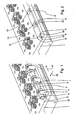
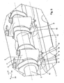
- the base body 1 is designed as a cylinder head and the shaft 2 as a camshaft and fastened on the bearing block 3 on the base body 1.
- the bearing block 3 is provided with an opening 4, in which the shaft 2 is rotatably mounted. Furthermore, the bearing block 3 is attached via fixing elements 5 to the base body 1.
- an engagement element 7 is provided at the contact portion 6 of the bearing block 3 and the base body 1, which engages in a counter-element region 8.
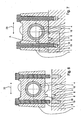
- the formed as a recess 9 counter-element region 8 has a line 10 within a surface in the groove-like Recess 9.
- the counter-element region 8 and the engagement element 7 are formed such that the bearing block 3 and the base body 1 in the assembled state and before assembly or without the attachment of fixing 5 form at least in one direction R along the line 10 no positive connection.
- at least the direction R of the line 10 forms a degree of freedom for the connection of the bearing block 3 on the base body 1.
- the degree of freedom takes place here without consideration of any frictional connection portions, for example. A press fit.
- the counter-element region 8 is formed in a straight line and thus the bearing block 3 relative to the base body 1 in the assembled state and without mounting the fixing means 5 along the straight line 10 form-fitting.
- the engagement element 7 is arranged as a prismatic emphasis on the bearing block 3 and the counter-element region 8 is formed on the base body 1 as a corresponding groove-like recess 9 wherein the engagement element 7 is integrally formed with the bearing block 3.
- the engagement element 7 is used as a separate component 11 on the one hand in the recess 9 of the base body 1 and on the other hand in the material recess 12 of the bearing block 3 and thereby also in one degree of freedom along the line 10 (here : vertically from the plane of the drawing) displaceable or this degree of freedom open holding connection forms.
- the separate component 11 does not necessarily have the cross-sectional contour shown, it may also have the shape of a triangle, a quadrangle, a rectangle, an n-corner, a semicircle, a semi-ellipse, a semi-oval curve or a trapezoid.
- the separate component 11 may be formed as a round rod, which rests in a correspondingly rounded recess 9 and / or material recess 12 (not shown).
- the base body 1 is provided with a plurality of spaced attachment portions 13, 13 ', 13 ", each having a recess 9.
- the respective recesses 9, 9', 9" lie in alignment with the straight line 10.
- a parallel or defined in their angular position, preferably the same orientation of the plurality of bearing blocks 3 is achieved.
- the alignment of the recess 9, 9 ', 9 "in alignment, preferably congruent, is recognizable to each other in particular from the drawing figures 2 and 4.
- the longitudinal axis 15 of the shaft 2 is aligned parallel to the line 10 and to the longitudinal axis 14 of the recess 9.
- the separate component 11 as generally described above for the engagement element, be provided with a tapered towards the free end (not shown).
- FIGS. 6 and 7 In drawing figure 8 is a detailed representation of the bearing block 3 with the base body 1 according to the dotted detail A from FIG. 7 shown. It can be seen that the fixing means 5 designed as a screw is provided within the bearing block 3 with a play 17, 17 'and engages in a provided with an internal thread 18 blind hole 19 in the base body 1.
- the engagement member 7 is designed as a rectangular to slightly prismatic in cross-section shaped pin, which engages in a similarly sized and geometrically similar shaped recess 9.
- the engaging element 7 is on a first side surface with a contact and alignment surface 21 and on one of the first opposite Side surface provided with a pressing surface or pressing line 22.
Landscapes
- Engineering & Computer Science (AREA)
- General Engineering & Computer Science (AREA)
- Mechanical Engineering (AREA)
- Mounting Of Bearings Or Others (AREA)
- Snaps, Bayonet Connections, Set Pins, And Snap Rings (AREA)
- Cylinder Crankcases Of Internal Combustion Engines (AREA)
Claims (14)
- Module de moteur constitué d'un corps de base (1), d'un arbre (2) ainsi que d'au moins un support de palier (3), le support de palier (3) comprenant une ouverture (4) pour la réception et le montage à rotation de l'arbre (2), le support de palier (3) étant fixé au corps de base (1) par le biais d'au moins un moyen de fixation (5) et l'arbre étant monté à rotation sur le corps de base à l'état de montage final, au moins un élément d'engagement (7) s'engageant dans une région d'élément conjugué (8) dans la région de contact (6) du support de palier (3) et du corps de base (1), la région d'élément conjugué (8) comprenant au moins une arête, réalisée en tant que ligne (10), d'un évidement (9) ou une ligne (10) à l'intérieur d'une surface d'un évidement (9), de préférence dans un évidement (9) de type rainure et la région d'élément conjugué (8) et l'au moins un élément d'engagement (7) étant réalisés de telle sorte que le support de palier (3) et le corps de base (1), à l'état assemblé et sans montage du moyen de fixation (5), ne forment aucune liaison par engagement par complémentarité de formes au moins dans une direction le long de la ligne (10), caractérisé en ce que l'élément d'engagement (7) et/ou la région d'élément conjugué (8) est/sont déformable(s) élastiquement et/ou plastiquement pendant le premier montage.
- Module de moteur selon la revendication précédente, caractérisé en ce que l'élément d'engagement (7) est disposé sur le support de palier (3) et la région d'élément conjugué (8) est disposée sur le corps de base (1), l'élément d'engagement (7) étant réalisé de préférence d'un seul tenant avec le support de palier (3) ou l'élément d'engagement (7) pouvant être inséré, en tant que composant séparé (11), dans un évidement de matériau (12) du support de palier (3).
- Module de moteur selon la revendication 1 ou 2, caractérisé en ce que la région d'élément conjugué (8) est réalisée de manière rectiligne, et en ce qu'il n'existe aucun engagement par complémentarité de formes le long de la ligne droite (10) entre le support de palier (3) et le corps de base (1) à l'état assemblé et sans montage du moyen de fixation (5).
- Module de moteur selon la revendication 3, caractérisé en ce que l'axe longitudinal (14) de la région d'élément conjugué rectiligne (8) forme avec l'axe longitudinal (15) de l'arbre (2) à l'état de montage final un angle α de 0° à 5°, de manière particulièrement préférée un angle de 0°, et s'étend par conséquent parallèlement à celui-ci.
- Module de moteur selon l'une quelconque des revendications précédentes, caractérisé en ce que l'élément d'engagement (7) et/ou la région d'élément conjugué (8) présente(nt) en section transversale la forme d'un triangle, d'un quadrilatère, d'un rectangle, d'un demi-cercle, d'une demi-ellipse, d'une courbe semi-ovale ou de manière particulièrement préférée la forme d'un trapèze.
- Module de moteur selon l'une quelconque des revendications précédentes, caractérisé en ce que l'élément d'engagement (7) est réalisé sous forme de relief et comprend une région se rétrécissant en direction de la région d'élément conjugué (8) et orientée vers la région d'élément conjugué (8) à l'état de montage final.
- Module de moteur selon l'une quelconque des revendications précédentes, caractérisé en ce que l'élément d'engagement (7) et la région d'élément conjugué (8) réalisent une liaison par force et/ou par serrage, et l'élément d'engagement (7) et la région d'élément conjugué (8) comprennent en l'occurrence, de manière particulièrement préférée, des matériaux de dureté et/ou de résistance différentes.
- Module de moteur selon l'une quelconque des revendications précédentes, caractérisé en ce qu'au moins une région du contour de la région d'élément conjugué (8) et/ou au moins une région du contour de l'élément d'engagement (7) est/sont formée(s) au moyen d'un procédé de fabrication par formage primaire et/ou par séparation.
- Module de moteur selon l'une quelconque des revendications précédentes, caractérisé en ce que le corps de base (1) comporte au moins une région d'application (13, 13', 13'') comprenant essentiellement une surface de contact plane, sur laquelle région d'application est disposé(e) l'élément d'engagement (7) ou la région d'élément conjugué (8), le support de palier (3) étant réalisé avec une surface de contact essentiellement correspondante et la surface de contact du support de palier (3) pouvant être appliquée contre la surface de contact de la région d'application (13, 13', 13'').
- Module de moteur selon la revendication 9, caractérisé en ce que le corps de base (1) comporte au moins deux régions d'application (13, 13', 13'') espacées l'une de l'autre, les régions d'élément conjugué rectilignes ou les éléments d'engagement des au moins deux régions d'application (13, 13', 13") étant disposé(e)s sur une ligne droite (10) et/ou parallèlement les un(e)s aux autres.
- Module de moteur selon l'une quelconque des revendications précédentes, caractérisé en ce que le corps de base (1) est réalisé sous forme de tête de cylindre et l'arbre (2) est réalisé sous forme d'arbre à cames ou d'équilibrage et/ou le corps de base (1) est réalisé sous forme de tête de cylindre et l'arbre (2) est réalisé sous forme d'axe de culbuteur.
- Module de moteur selon l'une quelconque des revendications précédentes, caractérisé en ce que le support de palier (3) est réalisé au moins en deux parties et comprend une partie inférieure ainsi qu'un couvercle, l'ouverture (4) pour la réception de l'arbre étant formée par la partie inférieure et le couvercle, et l'au moins un moyen de fixation (5) reliant les uns aux autres le couvercle, la partie inférieure ainsi que le corps de base (1),
les surfaces de contact du couvercle et de la partie inférieure réalisant de préférence un engagement par complémentarité de formes avec une liaison à rainure et languette et l'engagement par complémentarité de formes le long de la ligne (10) ne formant aucune liaison par engagement par complémentarité de formes. - Procédé de montage d'un arbre (2) pouvant être reçu et monté à rotation dans un support de palier (3) sur un corps de base (1), le support de palier (3) et le corps de base (1) comprenant un élément d'engagement (7) et une région d'élément conjugué (8) et le support de palier (3) étant relié au corps de base (1) par le biais de moyens de fixation (5), le procédé comportant les étapes suivantes :- fourniture d'un support de palier (3),- fourniture d'un corps de base (1) pourvu d'au moins une surface de contact,- application du support de palier (3) contre la surface de contact (6) du corps de base (1) et, lorsque le support de palier (3) et le corps de base (1) sont réunis, l'élément d'engagement (7) et la région d'élément conjugué (8) venant en prise l'un dans l'autre et le support de palier (3) et le corps de base (1) s'alignant l'un par rapport à l'autre de manière définie en ce qui concerne leur position dans la direction transversale (20) par rapport à l'arbre (2) et en ce qui concerne l'alignement angulaire,- alignement du support de palier (3) le long de l'axe longitudinal (15) de l'arbre (2) sur le corps de base (1) par déplacement du support de palier (3),- fixation du support de palier (3) sur le corps de base (1) et fixation de la position dans l'alignement longitudinal (15) du corps de base (1) et du support de palier (3) par insertion d'au moins un moyen de fixation (5),
caractérisé par
la déformation élastique et/ou plastique de l'élément d'engagement (7) et/ou de la région d'élément conjugué (8) pendant le premier serrage à fond de l'au moins un moyen de fixation (5). - Procédé de fabrication d'un corps de base selon l'une quelconque des revendications 1 à 13, caractérisé par l'insertion d'au moins deux régions d'élément conjugué (8) de type rainure dans au moins deux surfaces de contact (6) et/ou régions d'application (13, 13', 13'') différentes d'un corps de base (1) par un déplacement d'avance rectiligne d'un outil d'enlèvement de copeaux, l'outil d'enlèvement de copeaux étant de préférence une fraise à disque, une lame de scie ou un outil similaire à celle-ci.
Applications Claiming Priority (1)
| Application Number | Priority Date | Filing Date | Title |
|---|---|---|---|
| DE102011114786A DE102011114786A1 (de) | 2011-10-01 | 2011-10-01 | Motorbaugruppe umfassend einen Lagerbock sowie Verfahren zu deren Montage |
Publications (2)
| Publication Number | Publication Date |
|---|---|
| EP2574743A1 EP2574743A1 (fr) | 2013-04-03 |
| EP2574743B1 true EP2574743B1 (fr) | 2015-03-04 |
Family
ID=46762807
Family Applications (1)
| Application Number | Title | Priority Date | Filing Date |
|---|---|---|---|
| EP12005834.2A Active EP2574743B1 (fr) | 2011-10-01 | 2012-08-11 | Module de moteur comprenant un support de palier ainsi que son procédé de montage |
Country Status (5)
| Country | Link |
|---|---|
| EP (1) | EP2574743B1 (fr) |
| CN (1) | CN103089474B (fr) |
| BR (1) | BR102012024993B1 (fr) |
| DE (1) | DE102011114786A1 (fr) |
| RU (1) | RU2607570C2 (fr) |
Families Citing this family (6)
| Publication number | Priority date | Publication date | Assignee | Title |
|---|---|---|---|---|
| CN104653245A (zh) * | 2015-01-30 | 2015-05-27 | 奇瑞汽车股份有限公司 | 一种汽车发动机用凸轮轴 |
| AT517169B1 (de) * | 2015-04-28 | 2017-03-15 | Miba Sinter Austria Gmbh | Lageranordnung |
| GB2538975B (en) * | 2015-06-01 | 2018-04-04 | Jaguar Land Rover Ltd | Bearing cap having positioning projections. |
| AT518673B1 (de) | 2016-06-03 | 2018-03-15 | Miba Sinter Austria Gmbh | Lageranordnung |
| AT522877B1 (de) * | 2019-10-04 | 2021-03-15 | Miba Sinter Austria Gmbh | Lagerbock |
| CN114198407B (zh) * | 2021-12-15 | 2022-09-16 | 奇瑞汽车股份有限公司 | 发动机的轴承下盖和加工工艺方法、发动机 |
Family Cites Families (9)
| Publication number | Priority date | Publication date | Assignee | Title |
|---|---|---|---|---|
| DE1263394B (de) | 1964-04-09 | 1968-03-14 | Kloeckner Humboldt Deutz Ag | Brennkraftmaschine mit Betaetigung der Ventile mittels Kipphebel |
| US5387472A (en) * | 1992-05-20 | 1995-02-07 | Nelson Metal Products Corporation | Mated molded parts assembly and method for making same |
| CN1185521A (zh) * | 1996-12-19 | 1998-06-24 | 日野汽车工业株式会社 | 汽缸体 |
| JPH11107850A (ja) * | 1997-10-03 | 1999-04-20 | Honda Motor Co Ltd | 回転軸の支持構造及びエンジンにおけるクランク軸の支持構造 |
| AT3758U1 (de) * | 1999-08-30 | 2000-07-25 | Avl List Gmbh | Zylinderkopfstruktur für eine brennkraftmaschine |
| FR2815092B1 (fr) * | 2000-10-06 | 2003-02-14 | Renault | Ensemble de palier d'arbre a cames |
| JP4365373B2 (ja) * | 2006-01-19 | 2009-11-18 | トヨタ自動車株式会社 | 内燃機関のカムシャフト支持構造 |
| ES2326555T3 (es) * | 2007-02-09 | 2009-10-14 | Thyssenkrupp Presta Teccenter Ag | Procedimiento para el montaje de un conjunto constructivo premontado de arbol de levas. |
| JP2008215532A (ja) * | 2007-03-06 | 2008-09-18 | Toyota Motor Corp | クランクシャフトの軸受構造 |
-
2011
- 2011-10-01 DE DE102011114786A patent/DE102011114786A1/de not_active Withdrawn
-
2012
- 2012-08-11 EP EP12005834.2A patent/EP2574743B1/fr active Active
- 2012-09-18 RU RU2012139968A patent/RU2607570C2/ru active
- 2012-09-29 CN CN201210460438.9A patent/CN103089474B/zh not_active Expired - Fee Related
- 2012-10-01 BR BR102012024993-6A patent/BR102012024993B1/pt not_active IP Right Cessation
Also Published As
| Publication number | Publication date |
|---|---|
| CN103089474A (zh) | 2013-05-08 |
| BR102012024993A2 (pt) | 2013-11-05 |
| DE102011114786A1 (de) | 2013-04-04 |
| EP2574743A1 (fr) | 2013-04-03 |
| CN103089474B (zh) | 2017-08-04 |
| BR102012024993B1 (pt) | 2021-04-27 |
| RU2012139968A (ru) | 2014-03-27 |
| RU2607570C2 (ru) | 2017-01-10 |
Similar Documents
| Publication | Publication Date | Title |
|---|---|---|
| EP2861873B1 (fr) | Support pour rail profilé | |
| EP1320690B1 (fr) | Palier a collet pourvu d'un dispositif de centrage | |
| EP2574743A1 (fr) | Module de moteur comprenant un support de palier ainsi que son procédé de montage | |
| EP2613901B1 (fr) | Dispositif de fixation | |
| DE112013002230T5 (de) | Hauptlagerkappe mit Positionierungsmerkmal | |
| EP1554068B1 (fr) | Dispositif d'arrachage | |
| DE102008015154A1 (de) | Führungs- oder Spannschiene in einem Zugmitteltrieb | |
| EP1956222A1 (fr) | Bloc d'arbre à cames et son procédé de montage | |
| EP2745980B1 (fr) | Procédé d'assemblage thermique d'éléments fonctionnels non circulaires sur un arbre | |
| EP1044760A2 (fr) | Dispositif de serrage | |
| DE69215493T2 (de) | Haltevorrichtung mit entfernbarer Zentrierbüchse | |
| EP3964332A1 (fr) | Dispositif de serrage | |
| EP3536456B1 (fr) | Système de serrage | |
| DE102012011563A1 (de) | Halter für eine Profilschiene | |
| EP1607183B1 (fr) | Étau | |
| EP2978564B1 (fr) | Cage de serrage pourvue d'éléments de fixation | |
| DE202022104415U1 (de) | Schieberanordnung | |
| EP2213410B1 (fr) | Guidage linéaire avec dispositif de serrage | |
| WO2017215906A1 (fr) | Corps creux à symétrie de rotation et procédé pour sa fabrication | |
| DE2557248C3 (de) | Vorrichtung zum Feststellen von Maschinenteilen zueinander | |
| EP2626173B1 (fr) | Griffe de serrage pour un dispositif de serrage | |
| EP4476057B1 (fr) | Agencement à coulisseau | |
| EP1790862B1 (fr) | Support pour la broche de l'organe de manoeuvre du réglage d'un siège de véhicule à moteur | |
| DE102013106628A1 (de) | Verfahren zur Herstellung eines Presswerkzeuges | |
| DE102015225569A1 (de) | Werkzeug zum Schneiden eines Bauteils |
Legal Events
| Date | Code | Title | Description |
|---|---|---|---|
| PUAI | Public reference made under article 153(3) epc to a published international application that has entered the european phase |
Free format text: ORIGINAL CODE: 0009012 |
|
| AK | Designated contracting states |
Kind code of ref document: A1 Designated state(s): AL AT BE BG CH CY CZ DE DK EE ES FI FR GB GR HR HU IE IS IT LI LT LU LV MC MK MT NL NO PL PT RO RS SE SI SK SM TR |
|
| AX | Request for extension of the european patent |
Extension state: BA ME |
|
| 17P | Request for examination filed |
Effective date: 20130914 |
|
| RIC1 | Information provided on ipc code assigned before grant |
Ipc: F01L 1/047 20060101AFI20140716BHEP Ipc: F01L 1/053 20060101ALI20140716BHEP |
|
| GRAP | Despatch of communication of intention to grant a patent |
Free format text: ORIGINAL CODE: EPIDOSNIGR1 |
|
| INTG | Intention to grant announced |
Effective date: 20141205 |
|
| GRAS | Grant fee paid |
Free format text: ORIGINAL CODE: EPIDOSNIGR3 |
|
| GRAA | (expected) grant |
Free format text: ORIGINAL CODE: 0009210 |
|
| AK | Designated contracting states |
Kind code of ref document: B1 Designated state(s): AL AT BE BG CH CY CZ DE DK EE ES FI FR GB GR HR HU IE IS IT LI LT LU LV MC MK MT NL NO PL PT RO RS SE SI SK SM TR |
|
| REG | Reference to a national code |
Ref country code: GB Ref legal event code: FG4D Free format text: NOT ENGLISH |
|
| REG | Reference to a national code |
Ref country code: CH Ref legal event code: EP |
|
| REG | Reference to a national code |
Ref country code: IE Ref legal event code: FG4D Free format text: LANGUAGE OF EP DOCUMENT: GERMAN |
|
| REG | Reference to a national code |
Ref country code: AT Ref legal event code: REF Ref document number: 714095 Country of ref document: AT Kind code of ref document: T Effective date: 20150415 |
|
| REG | Reference to a national code |
Ref country code: DE Ref legal event code: R096 Ref document number: 502012002371 Country of ref document: DE Effective date: 20150416 |
|
| REG | Reference to a national code |
Ref country code: SE Ref legal event code: TRGR |
|
| REG | Reference to a national code |
Ref country code: NL Ref legal event code: T3 |
|
| PG25 | Lapsed in a contracting state [announced via postgrant information from national office to epo] |
Ref country code: ES Free format text: LAPSE BECAUSE OF FAILURE TO SUBMIT A TRANSLATION OF THE DESCRIPTION OR TO PAY THE FEE WITHIN THE PRESCRIBED TIME-LIMIT Effective date: 20150304 Ref country code: NO Free format text: LAPSE BECAUSE OF FAILURE TO SUBMIT A TRANSLATION OF THE DESCRIPTION OR TO PAY THE FEE WITHIN THE PRESCRIBED TIME-LIMIT Effective date: 20150604 Ref country code: LT Free format text: LAPSE BECAUSE OF FAILURE TO SUBMIT A TRANSLATION OF THE DESCRIPTION OR TO PAY THE FEE WITHIN THE PRESCRIBED TIME-LIMIT Effective date: 20150304 Ref country code: FI Free format text: LAPSE BECAUSE OF FAILURE TO SUBMIT A TRANSLATION OF THE DESCRIPTION OR TO PAY THE FEE WITHIN THE PRESCRIBED TIME-LIMIT Effective date: 20150304 Ref country code: HR Free format text: LAPSE BECAUSE OF FAILURE TO SUBMIT A TRANSLATION OF THE DESCRIPTION OR TO PAY THE FEE WITHIN THE PRESCRIBED TIME-LIMIT Effective date: 20150304 |
|
| REG | Reference to a national code |
Ref country code: LT Ref legal event code: MG4D |
|
| PG25 | Lapsed in a contracting state [announced via postgrant information from national office to epo] |
Ref country code: LV Free format text: LAPSE BECAUSE OF FAILURE TO SUBMIT A TRANSLATION OF THE DESCRIPTION OR TO PAY THE FEE WITHIN THE PRESCRIBED TIME-LIMIT Effective date: 20150304 Ref country code: RS Free format text: LAPSE BECAUSE OF FAILURE TO SUBMIT A TRANSLATION OF THE DESCRIPTION OR TO PAY THE FEE WITHIN THE PRESCRIBED TIME-LIMIT Effective date: 20150304 Ref country code: GR Free format text: LAPSE BECAUSE OF FAILURE TO SUBMIT A TRANSLATION OF THE DESCRIPTION OR TO PAY THE FEE WITHIN THE PRESCRIBED TIME-LIMIT Effective date: 20150605 |
|
| PG25 | Lapsed in a contracting state [announced via postgrant information from national office to epo] |
Ref country code: SK Free format text: LAPSE BECAUSE OF FAILURE TO SUBMIT A TRANSLATION OF THE DESCRIPTION OR TO PAY THE FEE WITHIN THE PRESCRIBED TIME-LIMIT Effective date: 20150304 Ref country code: CZ Free format text: LAPSE BECAUSE OF FAILURE TO SUBMIT A TRANSLATION OF THE DESCRIPTION OR TO PAY THE FEE WITHIN THE PRESCRIBED TIME-LIMIT Effective date: 20150304 Ref country code: RO Free format text: LAPSE BECAUSE OF FAILURE TO SUBMIT A TRANSLATION OF THE DESCRIPTION OR TO PAY THE FEE WITHIN THE PRESCRIBED TIME-LIMIT Effective date: 20150304 Ref country code: PT Free format text: LAPSE BECAUSE OF FAILURE TO SUBMIT A TRANSLATION OF THE DESCRIPTION OR TO PAY THE FEE WITHIN THE PRESCRIBED TIME-LIMIT Effective date: 20150706 Ref country code: EE Free format text: LAPSE BECAUSE OF FAILURE TO SUBMIT A TRANSLATION OF THE DESCRIPTION OR TO PAY THE FEE WITHIN THE PRESCRIBED TIME-LIMIT Effective date: 20150304 |
|
| PG25 | Lapsed in a contracting state [announced via postgrant information from national office to epo] |
Ref country code: IS Free format text: LAPSE BECAUSE OF FAILURE TO SUBMIT A TRANSLATION OF THE DESCRIPTION OR TO PAY THE FEE WITHIN THE PRESCRIBED TIME-LIMIT Effective date: 20150704 Ref country code: PL Free format text: LAPSE BECAUSE OF FAILURE TO SUBMIT A TRANSLATION OF THE DESCRIPTION OR TO PAY THE FEE WITHIN THE PRESCRIBED TIME-LIMIT Effective date: 20150304 |
|
| REG | Reference to a national code |
Ref country code: DE Ref legal event code: R097 Ref document number: 502012002371 Country of ref document: DE |
|
| PLBE | No opposition filed within time limit |
Free format text: ORIGINAL CODE: 0009261 |
|
| STAA | Information on the status of an ep patent application or granted ep patent |
Free format text: STATUS: NO OPPOSITION FILED WITHIN TIME LIMIT |
|
| PG25 | Lapsed in a contracting state [announced via postgrant information from national office to epo] |
Ref country code: DK Free format text: LAPSE BECAUSE OF FAILURE TO SUBMIT A TRANSLATION OF THE DESCRIPTION OR TO PAY THE FEE WITHIN THE PRESCRIBED TIME-LIMIT Effective date: 20150304 |
|
| 26N | No opposition filed |
Effective date: 20151207 |
|
| PG25 | Lapsed in a contracting state [announced via postgrant information from national office to epo] |
Ref country code: SI Free format text: LAPSE BECAUSE OF FAILURE TO SUBMIT A TRANSLATION OF THE DESCRIPTION OR TO PAY THE FEE WITHIN THE PRESCRIBED TIME-LIMIT Effective date: 20150304 |
|
| PG25 | Lapsed in a contracting state [announced via postgrant information from national office to epo] |
Ref country code: MC Free format text: LAPSE BECAUSE OF FAILURE TO SUBMIT A TRANSLATION OF THE DESCRIPTION OR TO PAY THE FEE WITHIN THE PRESCRIBED TIME-LIMIT Effective date: 20150304 Ref country code: LU Free format text: LAPSE BECAUSE OF FAILURE TO SUBMIT A TRANSLATION OF THE DESCRIPTION OR TO PAY THE FEE WITHIN THE PRESCRIBED TIME-LIMIT Effective date: 20150811 |
|
| REG | Reference to a national code |
Ref country code: CH Ref legal event code: PL |
|
| PG25 | Lapsed in a contracting state [announced via postgrant information from national office to epo] |
Ref country code: LI Free format text: LAPSE BECAUSE OF NON-PAYMENT OF DUE FEES Effective date: 20150831 Ref country code: CH Free format text: LAPSE BECAUSE OF NON-PAYMENT OF DUE FEES Effective date: 20150831 |
|
| REG | Reference to a national code |
Ref country code: IE Ref legal event code: MM4A |
|
| PG25 | Lapsed in a contracting state [announced via postgrant information from national office to epo] |
Ref country code: IE Free format text: LAPSE BECAUSE OF NON-PAYMENT OF DUE FEES Effective date: 20150811 |
|
| REG | Reference to a national code |
Ref country code: FR Ref legal event code: PLFP Year of fee payment: 5 |
|
| PG25 | Lapsed in a contracting state [announced via postgrant information from national office to epo] |
Ref country code: MT Free format text: LAPSE BECAUSE OF FAILURE TO SUBMIT A TRANSLATION OF THE DESCRIPTION OR TO PAY THE FEE WITHIN THE PRESCRIBED TIME-LIMIT Effective date: 20150304 |
|
| GBPC | Gb: european patent ceased through non-payment of renewal fee |
Effective date: 20160811 |
|
| PG25 | Lapsed in a contracting state [announced via postgrant information from national office to epo] |
Ref country code: SM Free format text: LAPSE BECAUSE OF FAILURE TO SUBMIT A TRANSLATION OF THE DESCRIPTION OR TO PAY THE FEE WITHIN THE PRESCRIBED TIME-LIMIT Effective date: 20150304 Ref country code: HU Free format text: LAPSE BECAUSE OF FAILURE TO SUBMIT A TRANSLATION OF THE DESCRIPTION OR TO PAY THE FEE WITHIN THE PRESCRIBED TIME-LIMIT; INVALID AB INITIO Effective date: 20120811 Ref country code: BG Free format text: LAPSE BECAUSE OF FAILURE TO SUBMIT A TRANSLATION OF THE DESCRIPTION OR TO PAY THE FEE WITHIN THE PRESCRIBED TIME-LIMIT Effective date: 20150304 |
|
| PG25 | Lapsed in a contracting state [announced via postgrant information from national office to epo] |
Ref country code: CY Free format text: LAPSE BECAUSE OF FAILURE TO SUBMIT A TRANSLATION OF THE DESCRIPTION OR TO PAY THE FEE WITHIN THE PRESCRIBED TIME-LIMIT Effective date: 20150304 |
|
| PG25 | Lapsed in a contracting state [announced via postgrant information from national office to epo] |
Ref country code: GB Free format text: LAPSE BECAUSE OF NON-PAYMENT OF DUE FEES Effective date: 20160811 Ref country code: BE Free format text: LAPSE BECAUSE OF NON-PAYMENT OF DUE FEES Effective date: 20150831 |
|
| REG | Reference to a national code |
Ref country code: FR Ref legal event code: PLFP Year of fee payment: 6 |
|
| PG25 | Lapsed in a contracting state [announced via postgrant information from national office to epo] |
Ref country code: TR Free format text: LAPSE BECAUSE OF FAILURE TO SUBMIT A TRANSLATION OF THE DESCRIPTION OR TO PAY THE FEE WITHIN THE PRESCRIBED TIME-LIMIT Effective date: 20150304 |
|
| PG25 | Lapsed in a contracting state [announced via postgrant information from national office to epo] |
Ref country code: MK Free format text: LAPSE BECAUSE OF FAILURE TO SUBMIT A TRANSLATION OF THE DESCRIPTION OR TO PAY THE FEE WITHIN THE PRESCRIBED TIME-LIMIT Effective date: 20150304 |
|
| REG | Reference to a national code |
Ref country code: FR Ref legal event code: PLFP Year of fee payment: 7 |
|
| REG | Reference to a national code |
Ref country code: AT Ref legal event code: MM01 Ref document number: 714095 Country of ref document: AT Kind code of ref document: T Effective date: 20170811 |
|
| PG25 | Lapsed in a contracting state [announced via postgrant information from national office to epo] |
Ref country code: AL Free format text: LAPSE BECAUSE OF FAILURE TO SUBMIT A TRANSLATION OF THE DESCRIPTION OR TO PAY THE FEE WITHIN THE PRESCRIBED TIME-LIMIT Effective date: 20150304 |
|
| PG25 | Lapsed in a contracting state [announced via postgrant information from national office to epo] |
Ref country code: AT Free format text: LAPSE BECAUSE OF NON-PAYMENT OF DUE FEES Effective date: 20170811 |
|
| REG | Reference to a national code |
Ref country code: DE Ref legal event code: R081 Ref document number: 502012002371 Country of ref document: DE Owner name: MAN TRUCK & BUS SE, DE Free format text: FORMER OWNER: MAN TRUCK & BUS AG, 80995 MUENCHEN, DE |
|
| PGFP | Annual fee paid to national office [announced via postgrant information from national office to epo] |
Ref country code: NL Payment date: 20250825 Year of fee payment: 14 |
|
| PGFP | Annual fee paid to national office [announced via postgrant information from national office to epo] |
Ref country code: DE Payment date: 20250827 Year of fee payment: 14 |
|
| PGFP | Annual fee paid to national office [announced via postgrant information from national office to epo] |
Ref country code: IT Payment date: 20250825 Year of fee payment: 14 |
|
| PGFP | Annual fee paid to national office [announced via postgrant information from national office to epo] |
Ref country code: FR Payment date: 20250825 Year of fee payment: 14 |
|
| PGFP | Annual fee paid to national office [announced via postgrant information from national office to epo] |
Ref country code: SE Payment date: 20250825 Year of fee payment: 14 |