EP2574747A1 - Verbindungsvorrichtung zur Verbindung von zwei Gehäuseteilen einer Brennkraftmaschine - Google Patents
Verbindungsvorrichtung zur Verbindung von zwei Gehäuseteilen einer Brennkraftmaschine Download PDFInfo
- Publication number
- EP2574747A1 EP2574747A1 EP12185772A EP12185772A EP2574747A1 EP 2574747 A1 EP2574747 A1 EP 2574747A1 EP 12185772 A EP12185772 A EP 12185772A EP 12185772 A EP12185772 A EP 12185772A EP 2574747 A1 EP2574747 A1 EP 2574747A1
- Authority
- EP
- European Patent Office
- Prior art keywords
- connecting flange
- adapter frame
- oil pan
- seal
- crankcase
- Prior art date
- Legal status (The legal status is an assumption and is not a legal conclusion. Google has not performed a legal analysis and makes no representation as to the accuracy of the status listed.)
- Granted
Links
Images


Classifications
-
- F—MECHANICAL ENGINEERING; LIGHTING; HEATING; WEAPONS; BLASTING
- F01—MACHINES OR ENGINES IN GENERAL; ENGINE PLANTS IN GENERAL; STEAM ENGINES
- F01M—LUBRICATING OF MACHINES OR ENGINES IN GENERAL; LUBRICATING INTERNAL COMBUSTION ENGINES; CRANKCASE VENTILATING
- F01M11/00—Component parts, details or accessories, not provided for in, or of interest apart from, groups F01M1/00 - F01M9/00
- F01M11/0004—Oilsumps
- F01M2011/0054—Fastening to the cylinder block
-
- F—MECHANICAL ENGINEERING; LIGHTING; HEATING; WEAPONS; BLASTING
- F01—MACHINES OR ENGINES IN GENERAL; ENGINE PLANTS IN GENERAL; STEAM ENGINES
- F01M—LUBRICATING OF MACHINES OR ENGINES IN GENERAL; LUBRICATING INTERNAL COMBUSTION ENGINES; CRANKCASE VENTILATING
- F01M11/00—Component parts, details or accessories, not provided for in, or of interest apart from, groups F01M1/00 - F01M9/00
- F01M11/0004—Oilsumps
- F01M2011/0062—Gaskets
Definitions
- the invention relates to a connecting device for connecting two housing parts of an internal combustion engine, having a first connecting flange, which is arranged on a first of the two housing parts, and a second connecting flange, which is arranged on a second of the two housing parts, and with a fastening device, with the the two connecting flanges are releasably sealed together.
- an oil pan for an internal combustion engine is made of a plastic material.
- the oil pan has a flange formed on its upper edge, on which a plurality of bores is arranged, are screwed by the screws in the engine block to fix the oil pan to this.
- the holes for receiving the screws can be formed by metallic press-fit bushes in the flange.
- the invention has for its object to design a connecting device of the type mentioned, in which the tightness of the connection between the first connecting flange and the second connecting flange is improved.
- a connecting device of the type mentioned, in which the tightness of the connection between the first connecting flange and the second connecting flange is improved.
- first connecting flange has a first sealing portion and the second connecting flange has a second sealing portion, which do not overlap in sealing gaps, and between the first connecting flange and the second connecting flange, an adapter frame is arranged, the first sealing portion and each fully overlaps the second sealing portion and which cooperates in the connecting state of the two housing parts directly or indirectly respectively with the first sealing portion and with the second sealing portion sealingly.
- the first connecting flange and the second connecting flange differ in their extent such that they do not completely overlap. Where the sealing portions of the connecting flanges do not completely overlap, this leads to sealing gaps in the seal between the two connecting flanges.
- an adapter frame is provided which completely covers the sealing portions of the two connecting flanges. In this way, both the first sealing portion, and the second sealing portion are each sealed from the adapter frame.
- the adapter frame thus enables a combination of housing parts, the connecting flanges have different dimensions. In this way, housing parts from a modular system with different connecting flanges can be tightly interconnected. Furthermore, manufacturing tolerances in the region of the connecting flanges can be easily compensated with the adapter frame.
- the adapter frame may advantageously have such a high dimensional stability that it can rest stably and tightly against the sealing portion of one of the connecting flanges, even if it is free on the opposite side of the sealing portion, that is no mechanical support by the other connecting flange experiences.
- the adapter frame can thus form an abutment for one-sided sealing sections in order to close the sealing gaps.
- one of the housing parts may be a crankcase and the other housing part may be an oil sump.
- the connecting flange on the side of the crankcase may be formed as a lead frame.
- one of the housing parts may be a cylinder head and the other housing part may be a cylinder head cover.
- the attachment means in the first connection flange may have a plurality of holes for screws and holes corresponding in the second connection flange, which are aligned with the holes in the first connection flange, and the two connection flanges may be screwed together with the screws.
- a screw connection can be easily realized.
- the two connecting flanges can be screwed together evenly. In this way it can be prevented that the connecting flanges warp during fixing, whereby leaks between connecting flanges can arise.
- the bolting force, which on the Both connecting flanges acts can be varied. A screw connection can be easily solved.
- a spacer bushing can be arranged.
- the spacer bushes can be easily prevented that the screws compress the material of the corresponding connecting flange.
- the material of the connecting flange can be protected against the screws. In this way, the requirement for the hardness of the material of the corresponding connecting flange may be lower.
- the connecting flange may be made of a softer material, in particular plastic.
- one of the connecting flanges, in particular the connecting flange, in which any distance bushes are arranged, for realizing the corresponding sealing portion have at least one sealing groove with a seal and the sealing groove and / or the seal may extend beyond the sealing portion of the other connecting flange.
- a seal in particular an elastic seal, can be stably accommodated.
- the seal can be easily pre-assembled in the seal groove.
- the seal is held in the seal groove.
- the sealing groove can act in the manner of a spacer, such that the seal can be compressed in the fixation of the two connecting flanges by means of the fastening device only to a limited extent.
- the sealing groove can advantageously rotate around the holes for the screws and the spacers from the inside of the housing parts inside, so that the seal can also seal the holes and the spacers to the interior of the housing parts.
- a seal made of liquid for mounting, later solid silicone can be easily applied to the corresponding connecting flange and / or the adapter frame.
- the liquid silicone can easily distribute along the corresponding sealing portion.
- the use of a liquid silicone seal simplifies assembly. Component tolerances can be easily compensated with a liquid silicone seal.
- the adapter frame and the connecting flange, between which the silicone gasket is arranged have a similar thermal expansion.
- At least the connecting flange of one of the housing parts in particular a crankcase or a cylinder head, be made of metal and at least the connecting flange of the other housing part, in particular an oil pan or a cylinder head cover, may be made of plastic.
- the one connecting flange, in particular the entire housing part can be easily formed and machined from metal. Metal may be stable, particularly with regard to high pressures and temperatures which may occur during operation of the internal combustion engine.
- the other connecting flange, in particular the entire housing part may be made of plastic with a low weight. Plastic parts can be easily manufactured. Furthermore, plastic parts can be easily recycled.
- the adapter frame may be made of a material having a similar coefficient of thermal expansion as the material from which at least the connecting flange of the housing part, in particular a crankcase or a cylinder head, which is closest to a combustion chamber of the internal combustion engine, preferably, the adapter frame and at least the connecting flange made of the same material, in particular the same metal, be.
- This has the advantage that movements of the adapter frame relative to the connecting flange with temperature changes, in particular heating of the housing part during operation of the internal combustion engine, can be avoided. In this way, the requirements for the mechanical properties of the seal between the adapter frame and the housing part, in particular their flexibility, may be lower.
- a seal made of liquid silicone can be used there.
- one of the housing parts in particular the housing part, which is furthest away to a combustion chamber of the internal combustion engine, preferably an oil pan or a cylinder head cover, a particular releasable holding device, in particular locking elements, have for holding the adapter frame with separate housing parts, especially before the assembly of the two housing parts.
- the adapter frame With the holding device, the adapter frame can be preassembled on the corresponding housing part. With the holding device, the adapter frame can be preferably held in the correct position on the housing part.
- the holding device can serve as a transport lock and / or as an assembly aid. By positioning the adapter frame with the holding device on the housing part, the mounting on the other housing part can be simplified.
- a releasable holding device also has the advantage that the adapter frame can be easily replaced.
- a locking element can also be easily opened and closed.
- a so-called crankcase lower part can form a first connecting flange.
- the first connection flange may be bounded by substantially straight-line connections.
- the first connecting flange may have a substantially rectangular shape.
- the first connecting flange may have bores.
- an adapter frame is arranged at the first connecting flange.
- the adapter frame is sealed to the first connecting flange, for example by a so-called liquid silicone seal in which a silicone is applied liquid, which can solidify, for example by crosslinking.
- the liquid silicone gasket may form a seal which lies as a closed curve between the adapter frame and the first connecting flange.
- the adapter frame points, especially in the area of the holes, a greater width than the first connecting flange.
- a second connecting flange of an oil pan is arranged on the adapter frame. Due to the greater width of the adapter frame, in particular in the region of the bores, a profile seal, for example a seal with a rectangular profile, which can be located in a groove of the oil pan, can be guided around the bores. As a result, the profile seal can be pressed against areas of the adapter frame, which are not covered by the first connecting flange.
- the bores in the first connecting flange may be used to fasten the oil pan by means of screws, for example, the screws being guided through openings in the oil pan and the groove being guided with the profile seal around the openings of the oil pan.
- the oil pan can be made essentially of plastic.
- the seals through the seal between the adapter frame and the crankcase lower part and the seal between the oil pan and adapter frame may preferably be guided around the holes on the inside of the oil pan so that the holes are outside the sealed volume of the crankcase bottom and sump.
- crankcase 10 of an otherwise not shown with internal combustion engine in isometric view.
- the crankcase 10 is made of a metal.
- an oil pan 12 made of plastic is attached by means of a total of 11 designated connecting device.
- the crankcase 10 On its underside facing the oil pan 12, the crankcase 10 has a circumferentially closed housing connecting flange 14 of the connecting device 11 in the manner of a leadframe.
- the housing connecting flange 14 has a plurality of threaded bores 16, which in the Figures 2 and 4 to 7 are shown. Axes of the threaded holes 16 are parallel to each other.
- the underside of the housing connecting flange 14 facing the oil pan 12 has a circumferentially closed housing sealing section 18. The threaded bores 16 are located within the housing sealing portion 18th
- a tank connection flange 20 of the connecting device 11 is formed at the upper edge of the oil pan 12 facing the crankcase 10.
- a tank connection flange 20 of the connecting device 11 is formed in the tub connection flange 20, a plurality of through holes 22 are arranged, which are accessible from outside the oil pan 12.
- the through-holes 22 are each aligned with one of the threaded bores 16 in the housing connecting flange 14.
- the through-holes 22 extend coaxially with the threaded bores 16.
- a spacer sleeve 24 is coaxially arranged in each through hole 22.
- the spacers 24 are preferably made of metal.
- the tub connecting flange 20 is widened on the inside facing the interior of the oil pan 12 and the outside facing away from the interior of the oil pan 12.
- a circumferential sealing groove 26 is arranged on the housing connecting flange 14 side facing in the tub connecting flange 20, a circumferential sealing groove 26 is arranged.
- the seal groove 26 forms a sealing portion of the tub connecting flange 20 of the oil pan 12.
- the seal groove 26 is open to the Gezzausverbinditatisflansch 14.
- the seal groove 26 bypasses the through holes 22 on the inside of the oil pan 12 facing side.
- the through holes 22 are each open on a peripheral side to the seal groove 26.
- the profile ring seal 28 may preferably be an elastomeric seal.
- the course of the profile ring seal 28 is adapted to the course of the sealing groove 26.
- the profile ring seal 28 seals in each case in the region of the through holes 22 against the peripheral sides of the spacers 24 there.
- the sealing groove 26 and the profile ring seal 28 project beyond the housing connecting flange 14 of the crankcase 10 and the housing sealing section 18. In the region of the through holes 22, the sealing groove 26 and the profile ring seal 28 do not overlap with the housing sealing section 18, so that sealing gaps 29 are realized there ,
- an adapter frame 30 of the connecting device 11 is arranged between the Gezzausverbinditatisflansch 14 and the tub connecting flange 20.
- the adapter frame 30 is flat on the side facing the tub connecting flange 20.
- the adapter frame 30 is made of a metal having a coefficient of thermal expansion similar to that of the housing connecting flange 14. Preferably, it is off the same metal. In this way, the Gezzausungsbinding flange 14 and the adapter frame 30 at a heating or cooling of the crankcase 10 has a similar extent.
- the adapter frame 30 has a plurality of through holes 32 which are aligned with the through holes 22 of the Tannenitatisflansches 20 and the threaded holes 16 of the Gesimousverbinditatisflansches 14 with mounted sump 12.
- the adapter frame 30 is widened on its inside facing the interior of the oil pan 12 inside and on the inside of the oil pan 12 facing away from the outside corresponding to the tub connecting flange 20.
- the side facing the Wanneneducationsflansch 20 of the adapter frame 30 covers the Wanneneducationsflansch 20, so also the seal groove 26 with the profile ring seal 28 and the through holes 22 with the spacer sleeves 24 completely.
- the adapter frame 30 is circumferentially close to the sealing ring seal 28, so indirectly to the realized by the sealing groove 26 sealing portion of the tub connecting flange 20 at.
- the slope 34 is located outside of the through holes 32 on the side facing the interior of the oil pan 12 side.
- the thinner region of the adapter frame 30 is located on the side facing the interior of the oil pan 12.
- the thicker region is located on the side facing away from the interior of the oil pan 12 side. In the thicker region and the through holes 32 are arranged.
- the edge of the slope 34 facing the thicker region of the adapter frame 30 is overlapped by the surface of the housing connecting flange 14 facing the tub connecting flange 20.
- a seal 36 is disposed of liquid silicone, which is cured after assembly.
- each latching element 40 comprises a U-shaped frame part 42, which projects beyond the tub connecting flange 20 with its open side facing the crankcase 10. Between the legs of the frame part 42 a parallel to the legs latch hook 44 is arranged, which also projects beyond the tub connecting flange 20. At its free end, the latching hook 44 is provided with a detent 46, which is located on the interior of the oil pan 12 facing side. The latching nose 46 tapers towards the free end of the latching hook 44 in a wedge-like manner.
- a distance between the housing connecting flange 14 facing side of Wanneneducationsflansches 20 and a stop 48 of the locking lug 46 is greater than the thickness of the thicker portion of the adapter frame 30.
- the latching hooks 44 can be bent from the interior of the oil pan 12 away to the outside elastically. When mounted adapter frame 30, the locking hooks 44 surround the adapter frame 30 from the outside and hold it so on the tub connecting flange 20 in the mounting position. By means of the latching elements 40, the adapter frame 30 can be preassembled on the oil pan 12.
- the crankcase 10 made of metal and the oil pan 12 are made of plastic separately from each other.
- the profile ring seal 28 is inserted into the sealing groove 26 of the tub connecting flange 20.
- the adapter frame 30 is placed with the slope 34 away from the side facing the tub connecting flange 20.
- the latching hooks 44 initially elastically spring outwards. As soon as the adapter frame 30 has passed the stops 48 of the latching noses 46, the latching hooks 44 spring back. The adapter frame 30 is held in place with the latching hooks 44.
- the liquid silicone is brought to realize the seal 36 circumferentially on the thicker portion of the adapter frame 30.
- the liquid silicone can also be applied to the housing sealing portion 18 of the Gezzausverbinditatisflansches 14.
- the oil pan 12 with the tub connecting flange 20 is positioned in advance on the housing connecting flange 14 so that the through holes 22, the through holes 32 of the adapter frame 30 and the threaded holes 16 are aligned.
- the screws 38 are inserted from the bottom of the oil pan 12 in the spacers 24, pushed through the through holes 32 and screwed into the threaded holes 16.
- the spacers 24 prevent it that the plastic material of the tub connecting flange 20 is compressed or damaged.
- the adapter frame 30 When tightening the screws 38, the still liquid liquid silicone between the adapter frame 30 and the housing sealing portion 18 is pressed and distributed. In this way, a tight connection between the adapter frame 30 and the housing sealing portion 18 by means of the slope 34 and the inner portion of the adapter frame 30, the distribution of the liquid silicone for the realization of the seal 36 between the housing sealing portion 18 and the adapter frame 30 can be improved.
- the adapter frame 30 is now located with one side close to the profile ring seal 28 of the tub connecting flange 20. On the other side, the adapter frame 30 is sealed against the housing sealing portion 18 by means of the seal 36.
- the adapter frame 30 forms on the side of the Georesuseitatisflansches 14 in the areas of the sealing gaps 29 an abutment for the profile ring seal 38th
- the two different types of seals namely the cured liquid silicone gasket 36 and the elastic profile ring gasket 28, allow the crankcase 10, at least the housing connection flange 14, and the sump 12, at least the tub connection flange 20, to be made of different materials.
- the different materials may also have different thermal expansion. Any displacements of the housing connection flange 14 relative to the tub connection flange 20 can be compensated by the seal 36 and the profile ring seal 28.
- the invention is not limited to a crankcase 10 to which an oil pan 12 is attached. Rather, it can also be used to connect different types of housing parts of an internal combustion engine, for example, a cylinder head with a cylinder head cover.
- the sealing groove 26 with the profile ring seal 28 may be arranged in the housing connecting flange 14 instead of in the tub connecting flange 20.
- the seal 36 of post-cure, cured silicone may be disposed between the adapter frame 30 and the tub connection flange 20 instead of between the adapter frame 30 and the housing connection flange 14.
- the housing connection flange 14 may alternatively or additionally also project beyond the tub connection flange 20.
- the adapter frame 30 forms an abutment for the protruding portions of the Gesimousverbinditatisflansches 14th
- the housing connection flange 14 and the tub connection flange 20 can also be connected to one another by means of a different fastening device, for example by means of a latching connection or a clamp connection.
- the material of the tub connecting flange 20 may be reinforced in the region of the through holes 22.
- the sump 12, preferably the tub connecting flange 20, and the crankcase 10, preferably the housing connecting flange 14, may also be of a material similar, for example, to their respective thermal expansion.
- only the housing connecting flange 14 may be made of metal.
- only the tub connecting flange 20 may be made of plastic.
- latching elements 40 instead of the latching elements 40, other types of holding devices for holding the adapter frame 30 may be provided.
- the latching elements 40 may be disposed on the housing connection flange 14 instead of the tub connection flange 20 in order to hold the adapter frame 30 against the housing connection flange 14. On the locking elements 40 can also be omitted.
Landscapes
- Engineering & Computer Science (AREA)
- Mechanical Engineering (AREA)
- General Engineering & Computer Science (AREA)
- Lubrication Details And Ventilation Of Internal Combustion Engines (AREA)
- Cylinder Crankcases Of Internal Combustion Engines (AREA)
Description
- Die Erfindung betrifft eine Verbindungsvorrichtung zur Verbindung von zwei Gehäuseteilen einer Brennkraftmaschine, mit einem ersten Verbindungsflansch, der an einem ersten der zwei Gehäuseteile angeordnet ist, und einem zweiten Verbindungsflansch, der an einem zweiten der zwei Gehäuseteile angeordnet ist, und mit einer Befestigungseinrichtung, mit der die zwei Verbindungsflansche lösbar dicht miteinander verbunden sind.
- Aus der
DE 10 2010 004 493 A1 ist eine Ölwanne für einen Verbrennungsmotor bekannt. Die Ölwanne besteht aus einem Kunststoffmaterial. Die Ölwanne besitzt einen an ihrem oberen Rand ausgebildeten Flansch, an dem eine Vielzahl von Bohrungen angeordnet ist, durch die Schrauben in den Motorblock geschraubt werden, um die Ölwanne an diesem zu fixieren. Die Bohrungen zur Aufnahme der Schrauben können durch metallische Einpressbuchsen im Flansch gebildet sein. - Der Erfindung liegt die Aufgabe zugrunde, eine Verbindungsvorrichtung der eingangs genannten Art auszugestalten, bei der die Dichtigkeit der Verbindung zwischen dem ersten Verbindungsflansch und dem zweiten Verbindungsflansch verbessert wird. Vorzugsweise sollen auch Verbindungsflansche, die nicht vollständig überlappen, gegeneinander abgedichtet werden.
- Diese Aufgabe wird erfindungsgemäß dadurch gelöst, dass der erste Verbindungsflansch einen ersten Dichtabschnitt aufweist und der zweite Verbindungsflansch einen zweiten Dichtabschnitt aufweist, die sich in Dichtlücken nicht überlappen, und zwischen dem ersten Verbindungsflansch und dem zweiten Verbindungsflansch ein Adapterrahmen angeordnet ist, der den ersten Dichtabschnitt und den zweiten Dichtabschnitt jeweils vollständig überlappt und der im Verbindungszustand der zwei Gehäuseteile mittelbar oder unmittelbar jeweils mit dem ersten Dichtabschnitt und mit dem zweiten Dichtabschnitt dichtend zusammenwirkt.
- Erfindungsgemäß unterscheiden sich der erste Verbindungsflansch und der zweite Verbindungsflansch in ihrer Ausdehnung derart, dass sie sich nicht vollständig überlappen. Dort, wo die Dichtabschnitte der Verbindungsflansche sich nicht vollständig überlappen, führt dies zu Dichtlücken in der Abdichtung zwischen den beiden Verbindungsflanschen. Um diese Dichtlücken zu schließen, ist ein Adapterrahmen vorgesehen, welcher die Dichtabschnitte der beiden Verbindungsflansche jeweils vollständig abdeckt. Auf diese Weise sind sowohl der erste Dichtabschnitt, als auch der zweite Dichtabschnitt jeweils gegenüber dem Adapterrahmen abgedichtet. Der Adapterrahmen ermöglicht so eine Kombination von Gehäuseteilen, deren Verbindungsflansche unterschiedliche Ausdehnungen haben. Auf diese Weise können Gehäuseteile aus einem Baukastensystem mit unterschiedlichen Verbindungsflanschen dicht miteinander verbunden werden. Ferner können mit dem Adapterrahmen Fertigungstoleranzen im Bereich der Verbindungsflansche einfach ausgeglichen werden. Der Adapterrahmen kann vorteilhafterweise eine so große Formstabilität aufweisen, dass er stabil und dicht an dem Dichtabschnitt eines der Verbindungsflansche anliegen kann, auch wenn er auf der dem Dichtabschnitt gegenüberliegenden Seite frei ist, das heißt keine mechanische Unterstützung durch den anderen Verbindungsflansch erfährt. Der Adapterrahmen kann so ein Gegenlager für einseitige Dichtabschnitte bilden, um die Dichtlücken zu schließen. Vorteilhafterweise kann eines der Gehäuseteile ein Kurbelgehäuse sein und das andere Gehäuseteil kann eine Ölwanne sein. Der Verbindungsflansch auf der Seite des Kurbelgehäuses kann als Leiterrahmen ausgebildet sein. Alternativ kann eines der Gehäuseteile ein Zylinderkopf sein und das andere Gehäuseteil kann eine Zylinderkopfhaube sein.
- Bei einer vorteilhaften Ausführungsform kann die Befestigungseinrichtung in dem ersten Verbindungsflansch eine Vielzahl von Löchern für Schrauben und in dem zweiten Verbindungsflansch entsprechende Löcher aufweisen, die mit den Löchern im ersten Verbindungsflansch fluchten, und die beiden Verbindungsflansche können mit den Schrauben miteinander verschraubt sein. Eine derartige Schraubverbindung kann einfach realisiert werden. Mittels der entlang der Verbindungsflansche angeordneten Schrauben können die beiden Verbindungsflansche gleichmäßig miteinander verschraubt werden. Auf diese Weise kann verhindert werden, dass sich die Verbindungsflansche beim Fixieren verziehen, wodurch Undichtigkeiten zwischen Verbindungsflanschen entstehen können. Bei einer Schraubverbindung kann die Verschraubungskraft, welche auf die beiden Verbindungsflansche wirkt, variiert werden. Eine Schraubverbindung kann einfach gelöst werden.
- Vorteilhafterweise kann wenigstens in einem Teil der Löcher, die den Köpfen der Schrauben zugewandt sind, jeweils eine Distanzbuchse angeordnet sein. Mit den Distanzbuchsen kann einfach verhindert werden, dass die Schrauben das Material des entsprechenden Verbindungsflansches verpressen. Somit kann das Material des Verbindungsflansches gegen die Schrauben geschützt werden. Auf diese Weise kann die Anforderung an die Härte des Materials des entsprechenden Verbindungsflansches geringer sein. Der Verbindungsflansch kann aus einem weicheren Material, insbesondere Kunststoff, sein.
- Bei einer weiteren vorteilhaften Ausführungsform kann einer der Verbindungsflansche, insbesondere der Verbindungsflansch, in dem etwaige Distanzbuchsen angeordnet sind, zur Realisierung des entsprechenden Dichtabschnitts wenigstens eine Dichtungsnut mit einer Dichtung aufweisen und die Dichtungsnut und/oder die Dichtung kann den Dichtabschnitt des anderen Verbindungsflansches überragen. In einer Dichtungsnut kann eine Dichtung, insbesondere eine elastische Dichtung, stabil untergebracht werden. Die Dichtung kann so einfach in der Dichtungsnut vormontiert werden. Beim Zusammenbau der Gehäuseteile wird die Dichtung in der Dichtungsnut gehalten. Ferner kann die Dichtungsnut in Art eines Abstandhalters wirken, derart, dass die Dichtung bei der Fixierung der beiden Verbindungsflansche mittels der Befestigungseinrichtung nur in einem begrenzten Maß komprimiert werden kann. Auf diese Weise kann einer Beschädigung der Dichtung insbesondere durch zu starke Verpressung entgegengewirkt werden. Durch den Adapterrahmen kann unabhängig von der Ausdehnung des Dichtabschnitts des anderen Verbindungsflansches auch für den Bereich der Dichtungsnut ein Gegenlager realisiert werden, an dem die Dichtung dicht anliegen kann. Die Dichtungsnut kann vorteilhafterweise die Löcher für die Schrauben und die Distanzbuchsen von der Innenseite der Gehäuseteile aus betrachtet innen umlaufen, so dass die Dichtung auch die Löcher und die Distanzbuchsen zum Inneren der Gehäuseteile hin abdichten kann.
- Vorteilhafterweise kann zwischen dem Adapterrahmen und einem der Dichtabschnitte insbesondere des Verbindungsflansches, welcher eine ähnliche Wärmeausdehnung wie der Adapterrahmen hat, eine Dichtung aus zur Montage flüssigem, später festem Silikon angeordnet sein. Eine Dichtung aus Flüssigsilikon, welche nach der Montage aushärtet, kann einfach auf den entsprechenden Verbindungsflansch und/oder den Adapterrahmen aufgebracht werden. Beim Aneinanderfügen des Verbindungsflansches und des Adapterrahmens und der Fixierung durch die Befestigungseinrichtung kann sich das Flüssigsilikon einfach entlang dem entsprechenden Dichtabschnitt verteilen. Die Verwendung einer Flüssigsilikondichtung vereinfacht die Montage. Mit einer Flüssigsilikondichtung können Bauteiltoleranzen einfach kompensiert werden. Vorteilhafterweise können der Adapterrahmen und der Verbindungsflansch, zwischen denen die Silikondichtung angeordnet ist, eine ähnliche Wärmeausdehnung aufweisen. Auf diese Weise kann die mechanische Belastung der Silikondichtung, insbesondere eine Dehnung oder Verformung, bei einer Temperaturveränderung, insbesondere einer Erwärmung eines der Verbindungsflansche, verringert werden. Auf diese Weise wird die Zuverlässigkeit der Dichtung verbessert. Auch kann so bei geringen Temperaturen, bei denen die Silikondichtung sich weiter verhärten kann, die Dichtheit verbessert werden.
- Bei einer weiteren vorteilhaften Ausführungsform kann wenigstens der Verbindungsflansch eines der Gehäuseteile, insbesondere eines Kurbelgehäuses oder eine Zylinderkopfs, aus Metall sein und wenigstens der Verbindungsflansch des anderen Gehäuseteils, insbesondere einer Ölwanne oder einer Zylinderkopfhaube, kann aus Kunststoff sein. Der eine Verbindungsflansch, insbesondere das ganze Gehäuseteil, kann aus Metall einfach geformt und bearbeitet werden. Metall kann insbesondere in Bezug auf hohe Drücke und Temperaturen, die beim Betrieb der Brennkraftmaschine auftreten können, stabil sein. Der andere Verbindungsflansch, insbesondere das ganze Gehäuseteil, kann aus Kunststoff mit einem geringen Gewicht ausgestaltet sein. Kunststoffteile können einfach hergestellt werden. Ferner können Kunststoffteile einfach recycelt werden.
- Vorteilhafterweise kann der Adapterrahmen aus einem Material sein, das einen ähnlichen Wärmeausdehnungskoeffizienten hat, wie das Material, aus dem wenigstens der Verbindungsflansch des Gehäuseteils, insbesondere eines Kurbelgehäuses oder eines Zylinderkopfs, ist, welches einem Brennraum der Brennkraftmaschine wärmeleittechnisch am nächsten ist, vorzugsweise können der Adapterrahmen und wenigstens der Verbindungsflansch aus dem gleichen Material, insbesondere dem gleichen Metall, sein. Dies hat den Vorteil, dass Bewegungen des Adapterrahmens relativ zu dem Verbindungsflansch bei Temperaturveränderungen, insbesondere Erwärmung des Gehäuseteils beim Betrieb der Brennkraftmaschine, vermieden werden können. Auf diese Weise können die Anforderungen an die mechanischen Eigenschaften der Dichtung zwischen dem Adapterrahmen und dem Gehäuseteil, insbesondere deren Flexibilität, geringer sein. So kann dort insbesondere eine Dichtung aus Flüssigsilikon verwendet werden.
- Bei einer weiteren vorteilhaften Ausführungsform kann eines der Gehäuseteile, insbesondere das Gehäuseteil, welches zu einem Brennraum der Brennkraftmaschine wärmeleittechnisch am weitesten entfernt ist, vorzugsweise eine Ölwanne oder eine Zylinderkopfhaube, eine insbesondere lösbare Halteeinrichtung, insbesondere Rastelemente, aufweisen zum Halten des Adapterrahmens bei getrennten Gehäuseteilen, insbesondere vor dem Zusammenbau der beiden Gehäuseteile. Mit der Halteeinrichtung kann der Adapterrahmen an dem entsprechenden Gehäuseteil vormontiert werden. Mit der Halteeinrichtung kann der Adapterrahmen vorzugsweise in der korrekten Position an dem Gehäuseteil gehalten werden. Die Halteeinrichtung kann als Transportsicherung und/oder als Montagehilfe dienen. Durch die Positionierung des Adapterrahmens mit der Halteeinrichtung an dem Gehäuseteil kann die Montage an dem anderen Gehäuseteil vereinfacht werden. Eine lösbare Halteeinrichtung hat darüber hinaus den Vorteil, dass der Adapterrahmen einfach ausgetauscht werden kann. Ein Rastelement kann darüber hinaus einfach geöffnet und geschlossen werden.
- Bei einer Ausführungsform, deren Merkmale mit den bereits dargestellten Merkmalen kombiniert werden können, kann ein sogenanntes Kurbelgehäuseunterteil einen ersten Verbindungsflansch bilden. Der erste Verbindungsflansch kann durch im Wesentlichen geradlinige Verbindungen begrenzt sein. Bevorzugt kann der erste Verbindungsflansch eine im Wesentlichen rechteckige Gestalt aufweisen. Zur Befestigung einer Ölwanne kann der erste Verbindungsflansch Bohrungen aufweisen. An dem ersten Verbindungsflansch ist ein Adapterrahmen angeordnet. Der Adapterrahmen ist mit dem ersten Verbindungsflansch abgedichtet, z.B. durch eine sogenannte Flüssigsilikondichtung, bei der ein Silikon flüssig aufgebracht wird, das sich z.B. durch Vernetzen verfestigen kann. Die Flüssigsilikondichtung kann eine Dichtung bilden, die als geschlossene Kurve zwischen Adapterrahmen und erstem Verbindungsflansch liegt. Der Adapterrahmen weist, insbesondere im Bereich der Bohrungen, einen größere Breite auf, als der erste Verbindungsflansch. An den Adapterrahmen ist ein zweiter Verbindungsflansch einer Ölwanne angeordnet. Durch die größere Breite des Adapterrahmens, insbesondere im Bereich der Bohrungen, kann eine Profildichtung, z.B. eine Dichtung mit Rechteckprofil, die sich in einer Nut der Ölwanne befinden kann, um die Bohrungen herumgeführt werden. Hierdurch kann die Profildichtung an Bereiche des Adapterrahmens angepresst werden, die nicht durch den ersten Verbindungsflansch abgedeckt sind. Hierdurch kann es z.B. ermöglicht werden, dass die Bohrungen im ersten Verbindungsflansch zur Befestigung der Ölwanne mittels z.B. Schrauben dienen können, wobei die Schrauben durch Öffnungen in der Ölwanne geführt werden und um die Öffnungen der Ölwanne herum die Nut mit der Profildichtung geführt ist. Die Ölwanne kann im Wesentlichen aus Kunststoff gefertigt sein. Die Abdichtungen durch die Dichtung zwischen Adapterrahmen und Kurbelgehäuseunterteil und die Dichtung zwischen Ölwanne und Adapterrahmen können bevorzugt auf der Innenseite der Ölwanne um die Bohrungen herum geführt sein, sodass sich die Bohrungen außerhalb des abgedichteten Volumens von Kurbelgehäuseunterteil und Ölwanne befinden.
- Weitere Vorteile, Merkmale und Einzelheiten der Erfindung ergeben sich aus der nachfolgenden Beschreibung, in der ein Ausführungsbeispiel der Erfindung anhand der Zeichnung näher erläutert wird. Der Fachmann wird die in der Zeichnung, der Beschreibung und den Ansprüchen in Kombination offenbarten Merkmale zweckmäßigerweise auch einzeln betrachten und zu sinnvollen weiteren Kombinationen zusammenfassen. Es zeigen schematisch
- Figur 1
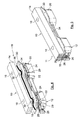
- eine isometrische Darstellung eines Kurbelgehäuses einer Brennkraftmaschine im Teilschnitt mit einer Ölwanne aus Kunststoff und einem Adapterrahmen, der zwischen Verbindungsflanschen des Kurbelgehäuses und der Ölwanne angeordnet ist;
- Figur 2
- einen Detailschnitt durch die Verbindungsflansche und den Adapterrahmen aus der
Figur 1 im Bereich einer Schraubverbindung; - Figur 3
- eine Draufsicht des Adapterrahmens aus den
Figuren 1 und2 ; - Figur 4
- einen Ausschnitt der Verbindungsflansche und des Adapterrahmens aus den
Figuren 1 und2 in einer Explosionsdarstellung von der Innenseite des Kurbelgehäuses aus betrachtet; - Figur 5
- den Ausschnitt der Verbindungsflansche des Adapterrahmens aus der
Figur 4 in montiertem Zustand; - Figur 6
- den Ausschnitt aus den
Figuren 4 und 5 in einer Explosionsdarstellung von der Außenseite des Kurbelgehäuses aus betrachtet; - Figur 7
- den Ausschnitt aus der
Figur 6 in montiertem Zustand; - Figur 8
- einen Detailschnitt des Verbindungsflansches der Ölwanne und des Adapterrahmens aus den
Figuren 1 bis 7 im Bereich eines Rastelements zum Halten des Adapterrahmens; - Figur 9
- eine isometrische Darstellung des Verbindungsflansches mit dem Rastelement aus der
Figur 8 . - In den Figuren sind gleiche Bauteile mit gleichen Bezugszeichen versehen.
- In der
Figur 1 ist ein Kurbelgehäuse 10 einer ansonsten nicht mit gezeigten Brennkraftmaschine in isometrischer Darstellung dargestellt. Das Kurbelgehäuse 10 besteht aus einem Metall. An der Unterseite des Kurbelgehäuses 10 ist mittels einer insgesamt mit 11 bezeichneten Verbindungsvorrichtung eine Ölwanne 12 aus Kunststoff befestigt. - An seiner der Ölwanne 12 zugewandten Unterseite weist das Kurbelgehäuse 10 einen umfangsmäßig geschlossenen Gehäuseverbindungsflansch 14 der Verbindungsvorrichtung 11 in Art eines Leiterrahmens auf. Der Gehäuseverbindungsflansch 14 weist eine Vielzahl von Gewindebohrungen 16 auf, welche in den
Figuren 2 und4 bis 7 gezeigt sind. Achsen der Gewindebohrungen 16 verlaufen parallel zueinander. Die der Ölwanne 12 zugewandte Unterseite des Gehäuseverbindungsflansches 14 weist einen umfangsmäßig geschlossenen Gehäusedichtabschnitt 18 auf. Die Gewindebohrungen 16 befinden sich innerhalb des Gehäusedichtabschnitts 18. - An dem dem Kurbelgehäuse 10 zugewandten oberen Rand der Ölwanne 12 ist ein Wannenverbindungsflansch 20 der Verbindungsvorrichtung 11 ausgebildet. In dem Wannenverbindungsflansch 20 ist eine Vielzahl von Durchgangslöchern 22 angeordnet, welche von außerhalb der Ölwanne 12 aus zugänglich sind. Bei montierter Ölwanne 12 fluchten die Durchgangslöcher 22 jeweils mit einer der Gewindebohrungen 16 im Gehäuseverbindungsflansch 14. Die Durchgangslöcher 22 verlaufen koaxial zu den Gewindebohrungen 16.
- In jedem Durchgangsloch 22 ist koaxial eine Distanzbuchse 24 angeordnet. Die Distanzbuchsen 24 sind vorzugsweise aus Metall. Im Bereich der Durchgangslöcher 22 mit den Distanzbuchsen 24 ist der Wannenverbindungsflansch 20 auf der dem Inneren der Ölwanne 12 zugewandten Innenseite und der dem Inneren der Ölwanne 12 abgewandten Außenseite jeweils verbreitert.
- Auf der dem Gehäuseverbindungsflansch 14 zugewandten Seite ist im Wannenverbindungsflansch 20 eine umlaufende Dichtungsnut 26 angeordnet. Die Dichtungsnut 26 bildet einen Dichtabschnitt des Wannenverbindungsflansches 20 der Ölwanne 12. Die Dichtungsnut 26 ist zum Gehäuseverbindungsflansch 14 hin offen. Die Dichtungsnut 26 umfährt die Durchgangslöcher 22 auf der dem Inneren der Ölwanne 12 zugewandten Seite. Die Durchgangslöcher 22 sind jeweils an einer Umfangsseite zu der Dichtungsnut 26 hin offen. In der Dichtungsnut 26 befindet sich eine elastische Profilringdichtung 28. Bei der Profilringdichtung 28 kann es sich vorzugsweise um eine Elastomerdichtung handeln. Der Verlauf der Profilringdichtung 28 ist an den Verlauf der Dichtungsnut 26 angepasst. Die Profilringdichtung 28 dichtet jeweils im Bereich der Durchgangslöcher 22 gegen die Umfangsseiten der dortigen Distanzbuchsen 24 ab.
- Bei montierter Ölwanne 12 überragen die Dichtungsnut 26 und die Profilringdichtung 28 den Gehäuseverbindungsflansch 14 des Kurbelgehäuses 10 und den Gehäusedichtabschnitt 18. Im Bereich der der Durchgangslöcher 22 überlappen die Dichtungsnut 26 und die Profilringdichtung 28 nicht mit dem Gehäusedichtabschnitt 18, so dass dort Dichtlücken 29 realisiert sind.
- Zwischen dem Gehäuseverbindungsflansch 14 und dem Wannenverbindungsflansch 20 ist ein Adapterrahmen 30 der Verbindungsvorrichtung 11 angeordnet. Der Adapterrahmen 30 ist auf der dem Wannenverbindungsflansch 20 zugewandten Seite eben. Der Adapterrahmen 30 ist aus einem Metall, welches einen ähnlichen Wärmeausdehnungskoeffizienten wie der Gehäuseverbindungsflansch 14 aufweist. Vorzugsweise ist er aus dem gleichen Metall. Auf diese Weise haben der Gehäuseverbindungsflansch 14 und der Adapterrahmen 30 bei einer Erwärmung oder Abkühlung des Kurbelgehäuses 10 eine ähnliche Ausdehnung.
- Der Adapterrahmen 30 weist eine Vielzahl von Durchgangslöchern 32 auf, welche bei montierter Ölwanne 12 mit den Durchgangslöchern 22 des Wannenverbindungsflansches 20 und den Gewindebohrungen 16 des Gehäuseverbindungsflansches 14 fluchten. Im Bereich der Durchgangslöcher 32 ist der Adapterrahmen 30 auf seiner dem Inneren der Ölwanne 12 zugewandten Innenseite und auf seiner dem Inneren der Ölwanne 12 abgewandten Außenseite entsprechend dem Wannenverbindungsflansch 20 verbreitert. Die dem Wannenverbindungsflansch 20 zugewandte Seite des Adapterrahmens 30 überdeckt den Wannenverbindungsflansch 20, also auch die Dichtungsnut 26 mit der Profilringdichtung 28 und die Durchgangslöcher 22 mit den Distanzbuchsen 24, vollständig. Der Adapterrahmen 30 liegt umfangsmäßig lückenlos dicht an der Profilringdichtung 28, also mittelbar an dem durch die Dichtungsnut 26 realisierten Dichtabschnitt des Wannenverbindungsflansches 20, an.
- Auf seiner dem Gehäuseverbindungsflansch 14 zugewandten Seite ist der Adapterrahmen 30 mittels einer Schräge 34 abgestuft. Die Schräge 34 befindet sich außerhalb der Durchgangslöcher 32 auf der dem Inneren der Ölwanne 12 zugewandten Seite. Der dünnere Bereich des Adapterrahmens 30 befindet sich auf der dem Inneren der Ölwanne 12 zugewandten Seite. Der dickere Bereich befindet sich auf der dem Inneren der Ölwanne 12 abgewandten Seite. In dem dickeren Bereich sind auch die Durchgangslöcher 32 angeordnet. Die dem dickeren Bereich des Adapterrahmens 30 zugewandte Kante der Schräge 34 wird im montierten Zustand von der dem Wannenverbindungsflansch 20 zugewandten Oberfläche des Gehäuseverbindungsflansches 14 überlappt.
- Zwischen dem dickeren Bereich des Adapterrahmens 30 und dem Gehäusedichtabschnitt 18 des Gehäuseverbindungsflansches 14 ist eine Dichtung 36 aus Flüssigsilikon angeordnet, welches nach der Montage ausgehärtet ist.
- Zur lösbaren Befestigung der Ölwanne 12 am Kurbelgehäuse 10 führen Schrauben 38 von außen durch die Distanzbuchsen 24 und die Durchgangslöcher 32 des Adapterrahmens 30 in die Gewindebohrungen 16. Die Köpfe der Schrauben 38 sind von außen zugänglich auf der dem Gehäuseverbindungsflansch 14 abgewandten Seite des Wannenverbindungsflansches 20 angeordnet.
- Auf der dem Inneren der Ölwanne 12 abgewandten Außenseite des Wannenverbindungsflansches 20 ist eine Mehrzahl von Rastelementen 40 der Verbindungsvorrichtung 11 angeordnet. Die Rastelemente 40 sind einstückig mit dem Wannenverbindungsflansch 20 verbunden. Jedes Rastelement 40 umfasst ein U-förmiges Rahmenteil 42, das mit seiner offenen Seite, die zum Kurbelgehäuse 10 hin zeigt, den Wannenverbindungsflansch 20 überragt. Zwischen den Schenkeln des Rahmenteils 42 ist ein zu den Schenkeln paralleler Rasthaken 44 angeordnet, welcher den Wannenverbindungsflansch 20 ebenfalls überragt. An seinem freien Ende ist der Rasthaken 44 mit einer Rastnase 46 versehen, die sich auf der dem Inneren der Ölwanne 12 zugewandten Seite befindet. Die Rastnase 46 spitzt sich zum freien Ende des Rasthakens 44 hin keilartig zu. Ein Abstand zwischen der dem Gehäuseverbindungsflansch 14 zugewandten Seite des Wannenverbindungsflansches 20 und einem Anschlag 48 der Rastnase 46 ist größer als die Dicke des dickeren Bereichs des Adapterrahmens 30. Die Rasthaken 44 können vom Inneren der Ölwanne 12 weg nach außen elastisch gebogen werden. Bei montiertem Adapterrahmen 30 umgreifen die Rasthaken 44 den Adapterrahmen 30 von außen und halten ihn so an dem Wannenverbindungsflansch 20 in Montageposition. Mittels der Rastelemente 40 kann der Adapterrahmen 30 an der Ölwanne 12 vormontiert werden.
- Zur Fertigung der Brennkraftmaschine werden das Kurbelgehäuse 10 aus Metall und die Ölwanne 12 aus Kunststoff separat voneinander hergestellt. Die Profilringdichtung 28 wird in die Dichtungsnut 26 des Wannenverbindungsflansches 20 eingelegt. Anschließend wird der Adapterrahmen 30 mit der der Schräge 34 abgewandten Seite voran auf den Wannenverbindungsflansch 20 gelegt. Dabei federn die Rasthaken 44 zunächst elastisch nach außen. Sobald der Adapterrahmen 30 die Anschläge 48 der Rastnasen 46 passiert hat, federn die Rasthaken 44 zurück. Der Adapterrahmen 30 wird mit den Rasthaken 44 in Position gehalten.
- Das Flüssigsilikon wird zur Realisierung der Dichtung 36 umlaufend auf den dickeren Bereich des Adapterrahmens 30 gebracht. Alternativ kann das Flüssigsilikon auch auf den Gehäusedichtabschnitt 18 des Gehäuseverbindungsflansches 14 aufgebracht werden. Anschließend wird die Ölwanne 12 mit dem Wannenverbindungsflansch 20 voran so an dem Gehäuseverbindungsflansch 14 positioniert, dass die Durchganglöcher 22, die Durchgangslöcher 32 des Adapterrahmens 30 und die Gewindebohrungen 16 fluchten. Schließlich werden die Schrauben 38 von der Unterseite der Ölwanne 12 aus in die Distanzbuchsen 24 gesteckt, durch die Durchgangslöcher 32 geschoben und in die Gewindebohrungen 16 geschraubt. Die Distanzbuchsen 24 verhindern dabei, dass das Kunststoffmaterial des Wannenverbindungsflansches 20 komprimiert oder beschädigt wird.
- Beim Anziehen der Schrauben 38 wird das noch flüssige Flüssigsilikon zwischen dem Adapterrahmen 30 und dem Gehäusedichtabschnitt 18 verpresst und verteilt. Auf diese Weise entsteht eine dichte Verbindung zwischen dem Adapterrahmen 30 und dem Gehäusedichtabschnitt 18. Mittels der Schräge 34 und dem inneren Bereich des Adapterrahmens 30 kann die Verteilung des Flüssigsilikons zur Realisierung der Dichtung 36 zwischen dem Gehäusedichtabschnitt 18 und dem Adapterrahmen 30 verbessert werden. Der Adapterrahmen 30 liegt nun mit einer Seite dicht an der Profilringdichtung 28 des Wannenverbindungsflansches 20 an. Auf der anderen Seite liegt der Adapterrahmen 30 mittels der Dichtung 36 abgedichtet dicht am Gehäusedichtabschnitt 18 an. Der Adapterrahmen 30 bildet auf der Seite des Gehäuseverbindungsflansches 14 auch in den Bereichen der Dichtungslücken 29 ein Gegenlager für die Profilringdichtung 38.
- Die beiden unterschiedlichen Dichtungsarten, nämlich die Dichtung 36 aus ausgehärtetem Flüssigsilikon und die elastische Profilringdichtung 28, ermöglichen, dass das Kurbelgehäuse 10, zumindest der Gehäuseverbindungsflansch 14, und die Ölwanne 12, zumindest der Wannenverbindungsflansch 20, aus unterschiedlichen Materialien sein können. Beispielsweise können die unterschiedlichen Materialien auch unterschiedliche Wärmeausdehnung besitzen. Etwaige Verschiebungen des Gehäuseverbindungsflansches 14 relativ zum Wannenverbindungsflansch 20 können durch die Dichtung 36 und Profilringdichtung 28 kompensiert werden.
- Bei dem oben beschriebenen Ausführungsbeispiel einer Verbindungsvorrichtung 11 sind unter anderem folgende Modifikationen möglich:
- Die Erfindung ist nicht beschränkt auf ein Kurbelgehäuse 10, an dem eine Ölwanne 12 befestigt ist. Vielmehr kann sie auch zur Verbindung von andersartigen Gehäuseteilen einer Brennkraftmaschine, beispielsweise auch eines Zylinderkopfs mit einer Zylinderkopfhaube, verwendet werden.
- Die Dichtungsnut 26 mit der Profilringdichtung 28 kann statt im Wannenverbindungsflansch 20 auch im Gehäuseverbindungsflansch 14 angeordnet sein.
- Die Dichtung 36 aus nach der Montage aushärtendem Flüssigsilikon kann statt zwischen dem Adapterrahmen 30 und dem Gehäuseverbindungsflansch 14 auch zwischen dem Adapterrahmen 30 und dem Wannenverbindungsflansch 20 angeordnet sein.
- Der Gehäuseverbindungsflansch 14 kann alternativ oder zusätzlich auch den Wannenverbindungsflansch 20 überragen. In diesem Fall bildet der Adapterrahmen 30 ein Gegenlager für die überstehenden Abschnitte des Gehäuseverbindungsflansches 14.
- Statt mit den Schrauben 38 können der Gehäuseverbindungsflansch 14 und der Wannenverbindungsflansch 20 auch mittels einer andersartigen Befestigungseinrichtung, beispielsweise mittels einer Rastverbindung oder eine Klammerverbindung, miteinander verbunden sein.
- Auf die Distanzbuchsen 24 kann auch verzichtet werden. Vorzugsweise kann das Material des Wannenverbindungsflansches 20 im Bereich der Durchgangslöcher 22 verstärkt sein.
- Die Ölwanne 12, vorzugsweise der Wannenverbindungsflansch 20, und das Kurbelgehäuse 10, vorzugsweise der Gehäuseverbindungsflansch 14, können auch aus einem beispielsweise bezüglich seiner jeweiligen Wärmeausdehnung ähnlichen Material sein.
- Statt des gesamten Kurbelgehäuses 10 kann auch nur der Gehäuseverbindungsflansch 14 aus Metall sein. Statt der gesamten Ölwanne 12 kann auch nur der Wannenverbindungsflansch 20 aus Kunststoff sein.
- Statt der Rastelemente 40 können auch andersartige Halteeinrichtungen zum Halten des Adapterrahmens 30 vorgesehen sein. Die Rastelemente 40 können statt am Wannenverbindungsflansch 20 auch am Gehäuseverbindungsflansch 14 angeordnet sein, um den Adapterrahmen 30 an dem Gehäuseverbindungsflansch 14 zu halten. Auf die Rastelemente 40 kann auch verzichtet werden.
Claims (11)
- Verbindungsvorrichtung (11) zur Verbindung von zwei Gehäuseteilen (10, 12) einer Brennkraftmaschine, mit einem ersten Verbindungsflansch (14), der an einem ersten der zwei Gehäuseteile (10) angeordnet ist, und einem zweiten Verbindungsflansch (20), der an einem zweiten der zwei Gehäuseteile (12) angeordnet ist, und mit einer Befestigungseinrichtung (22, 24, 32, 38), mit der die zwei Verbindungsflansche (14, 20) lösbar dicht miteinander verbunden sind, dadurch gekennzeichnet, dass der erste Verbindungsflansch (10) einen ersten Dichtabschnitt (18) aufweist und der zweite Verbindungsflansch (20) einen zweiten Dichtabschnitt (26) aufweist, die sich in Dichtlücken (29) nicht überlappen, und zwischen dem ersten Verbindungsflansch (14) und dem zweiten Verbindungsflansch (20) ein Adapterrahmen (30) angeordnet ist, der den ersten Dichtabschnitt (18) und den zweiten Dichtabschnitt (26) jeweils vollständig überlappt und der im Verbindungszustand der zwei Gehäuseteile (10, 12) mittelbar oder unmittelbar jeweils mit dem ersten Dichtabschnitt (18) und mit dem zweiten Dichtabschnitt (26) dichtend zusammenwirkt.
- Verbindungsvorrichtung nach Anspruch 1, dadurch gekennzeichnet, dass die Befestigungseinrichtung in dem einen Verbindungsflansch (14) eine Vielzahl von Löchern (16) für Schrauben (38) und in dem anderen Verbindungsflansch (20) entsprechende Löcher (22) aufweist, die mit den Löchern (16) im dem einen Verbindungsflansch (14) fluchten, und die beiden Verbindungsflansche (14, 20) mit den Schrauben (38) miteinander verschraubt sind.
- Verbindungsvorrichtung nach Anspruch 2, dadurch gekennzeichnet, dass wenigstens in einem Teil der Löcher (22), die den Köpfen der Schrauben (38) zugewandt sind, jeweils eine Distanzbuchse (24) angeordnet ist.
- Verbindungsvorrichtung nach einem der vorigen Ansprüche, dadurch gekennzeichnet, dass einer der Verbindungsflansche, insbesondere der Verbindungsflansch (20), in dem etwaige Distanzbuchse (24) angeordnet sind, zur Realisierung des entsprechenden Dichtabschnitts wenigstens eine Dichtungsnut (26) mit einer Dichtung (28) aufweist und die Dichtungsnut (26) und/oder die Dichtung (28) den Dichtabschnitt (18) des anderen Verbindungsflansches (14) überragt.
- Verbindungsvorrichtung nach einem der vorigen Ansprüche, dadurch gekennzeichnet, dass zwischen dem Adapterrahmen (30) und einem der Dichtabschnitte (18) insbesondere des Verbindungsflansches (14), welcher eine ähnliche Wärmeausdehnung wie der Adapterrahmen (30) hat, eine Dichtung (36) aus zur Montage flüssigem, später festem Silikon angeordnet ist.
- Verbindungsvorrichtung nach einem der vorigen Ansprüche, dadurch gekennzeichnet, dass wenigstens der Verbindungsflansch (14) eines der Gehäuseteile, insbesondere eines Kurbelgehäuses (10) oder eines Zylinderkopfs, aus Metall ist und wenigstens der Verbindungsflansch (20) des anderen Gehäuseteils, insbesondere einer Ölwanne (12) oder einer Zylinderkopfhaube, aus Kunststoff ist.
- Verbindungsvorrichtung nach einem der vorigen Ansprüche, dadurch gekennzeichnet, dass der Adapterrahmen (30) aus einem Material ist, das einen ähnlichen Wärmeausdehnungskoeffizienten hat, wie das Material, aus dem wenigstens der Verbindungsflansch (14) des Gehäuseteils, insbesondere eines Kurbelgehäuses (10) oder eines Zylinderkopfs, ist, welches einem Brennraum der Brennkraftmaschine wärmeleittechnisch am nächsten ist, vorzugsweise sind der Adapterrahmen (30) und wenigstens der Verbindungsflansch (14) aus dem gleichen Material, insbesondere dem gleichen Metall.
- Verbindungsvorrichtung nach einem der vorigen Ansprüche, dadurch gekennzeichnet, dass eines der Gehäuseteile, insbesondere das Gehäuseteil, welches zu einem Brennraum der Brennkraftmaschine wärmeleittechnisch am weitesten entfernt ist, vorzugsweise eine Ölwanne (12) oder eine Zylinderkopfhaube, eine insbesondere lösbare Halteeinrichtung, insbesondere Rastelemente (40), aufweist zum Halten des Adapterrahmens (30) bei getrennten Gehäuseteilen (10, 12), insbesondere vor dem Zusammenbau der beiden Gehäuseteile (10, 12).
- Kurbelgehäuseunterteil und Ölwanne (12), wobeii. das Kurbelgehäuseunterteil einen ersten Verbindungsflansch (14) mit Bohrungen zur Befestigung einer Ölwanne aufweist,ii. an dem Kurbelgehäuseunterteil ein Adapterrahmen (30) auf dem ersten Verbindungsflansch (14) dichtend angebracht ist, wobeiiii. der Adapterrahmen (30) zumindest im Bereich der Bohrungen eine größere Breite aufweist als der Verbindungsflansch,iv. eine Ölwanne (12) einen zweiten Verbindungsflansch (20) aufweist sowie Löcher zur Befestigung der Ölwanne (12) mittels Schrauben an einem Kurbelgehäuseunterteil,v. an der Ölwanne (12) eine Dichtung, insbesondere eine Profildichtung, angebracht ist, wobeivi. die Ölwanne (12) dichtend am Adapterrahmen angebracht ist, derart dass zumindest im Bereich der Bohrungen des Kurbelgehäuseunterteils und der Löcher zur Befestigung der Ölwanne (12) die Dichtung an der Ölwanne (12) an den Adapterrahmen (30) zumindest abschnittsweise in Bereichen angepresst wird, in denen der Adapterrahmen (30) nicht durch den ersten Verbindungsflansch (14) abgedeckt wird.
- Kurbelgehäuseunterteil und Ölwanne nach Anspruch 9, wobei die Dichtung an der Ölwanne (12) im Bereich zwischen den Bohrungen des Kurbelgehäuseunterteils und der Löcher zur Befestigung der Ölwanne (12) an den Adapterrahmen (30) zumindest abschnittsweise in Bereichen angepresst wird, in denen der Adapterrahmen (30) durch den ersten Verbindungsflansch (14) abgedeckt wird.
- Kurbelgehäuseunterteil und Ölwanne nach einem der Ansprüche 9 und 10 mit einer Verbindungsvorrichtung nach einem der Ansprüche 1 bis 8.
Applications Claiming Priority (1)
| Application Number | Priority Date | Filing Date | Title |
|---|---|---|---|
| DE102011114352A DE102011114352A1 (de) | 2011-09-27 | 2011-09-27 | Verbindungsvorrichtung zur Verbindung von zwei Gehäuseteilen einer Brennkraftmaschine |
Publications (2)
| Publication Number | Publication Date |
|---|---|
| EP2574747A1 true EP2574747A1 (de) | 2013-04-03 |
| EP2574747B1 EP2574747B1 (de) | 2019-05-22 |
Family
ID=46939629
Family Applications (1)
| Application Number | Title | Priority Date | Filing Date |
|---|---|---|---|
| EP12185772.6A Active EP2574747B1 (de) | 2011-09-27 | 2012-09-25 | Verbindungsvorrichtung zur Verbindung von zwei Gehäuseteilen einer Brennkraftmaschine |
Country Status (3)
| Country | Link |
|---|---|
| EP (1) | EP2574747B1 (de) |
| CN (1) | CN203374386U (de) |
| DE (1) | DE102011114352A1 (de) |
Families Citing this family (3)
| Publication number | Priority date | Publication date | Assignee | Title |
|---|---|---|---|---|
| GB2542594B (en) * | 2015-09-24 | 2019-10-16 | Ford Global Tech Llc | Machinery Casing Portion |
| CN109591991B (zh) * | 2018-12-12 | 2021-05-11 | 中国北方发动机研究所(天津) | 一种用于发动机适配舷外机动力舱的中间板 |
| DE102019127874A1 (de) * | 2019-10-16 | 2021-04-22 | Bayerische Motoren Werke Aktiengesellschaft | Ölwanne für Kraftfahrzeuge mit zusätzlichen Verbindungspunkten |
Citations (2)
| Publication number | Priority date | Publication date | Assignee | Title |
|---|---|---|---|---|
| FR2882782A1 (fr) * | 2005-03-03 | 2006-09-08 | Meillor Sa Sa | Carter pour lubrifiant |
| DE102010004493A1 (de) | 2010-01-12 | 2011-07-21 | MANN+HUMMEL GmbH, 71638 | Ölwanne für einen Verbrennungsmotor |
Family Cites Families (6)
| Publication number | Priority date | Publication date | Assignee | Title |
|---|---|---|---|---|
| AT402331B (de) * | 1992-01-24 | 1997-04-25 | Avl Verbrennungskraft Messtech | Hubkolbenmaschine, insbesondere brennkraftmaschine mit v-förmiger anordnung der zylinder oder zylinderreihen |
| DE19902817A1 (de) * | 1999-01-25 | 2000-07-27 | Loctite Deutschland Gmbh | Verfahren zum Anbringen der Ölwanne an einem Motorblock einer Verbrennungskraftmaschine |
| JP4365373B2 (ja) * | 2006-01-19 | 2009-11-18 | トヨタ自動車株式会社 | 内燃機関のカムシャフト支持構造 |
| FR2917464B1 (fr) * | 2007-06-12 | 2009-09-18 | Peugeot Citroen Automobiles Sa | Moteur a combustion interne comportant un dispositif de tension de chaine integre a la culasse |
| DE202008004036U1 (de) * | 2008-03-20 | 2009-08-06 | Mann+Hummel Gmbh | Ölwanne für eine Brennkraftmaschine |
| DE202009010125U1 (de) * | 2009-07-24 | 2009-10-01 | Fev Motorentechnik Gmbh | Mehrzylindrige Brennkraftmaschine |
-
2011
- 2011-09-27 DE DE102011114352A patent/DE102011114352A1/de not_active Withdrawn
-
2012
- 2012-09-25 EP EP12185772.6A patent/EP2574747B1/de active Active
- 2012-09-27 CN CN201220502536.XU patent/CN203374386U/zh not_active Expired - Lifetime
Patent Citations (2)
| Publication number | Priority date | Publication date | Assignee | Title |
|---|---|---|---|---|
| FR2882782A1 (fr) * | 2005-03-03 | 2006-09-08 | Meillor Sa Sa | Carter pour lubrifiant |
| DE102010004493A1 (de) | 2010-01-12 | 2011-07-21 | MANN+HUMMEL GmbH, 71638 | Ölwanne für einen Verbrennungsmotor |
Also Published As
| Publication number | Publication date |
|---|---|
| EP2574747B1 (de) | 2019-05-22 |
| CN203374386U (zh) | 2014-01-01 |
| DE102011114352A1 (de) | 2013-03-28 |
Similar Documents
| Publication | Publication Date | Title |
|---|---|---|
| EP1789670B1 (de) | Zylinderkopfhaube für einen zylinderkopf einer brennkraftmaschine | |
| EP1290363B1 (de) | Dichtungsanordnung | |
| EP2154339A1 (de) | Ölwanne mit Öfilter an Trägereinheit | |
| DE102013208984A1 (de) | Steuergerät | |
| EP2574747B1 (de) | Verbindungsvorrichtung zur Verbindung von zwei Gehäuseteilen einer Brennkraftmaschine | |
| EP2177725B2 (de) | Filtereinrichtung | |
| EP1739297A2 (de) | Zylinderkopfhaube einer Brennkraftmaschine | |
| DE202008004036U1 (de) | Ölwanne für eine Brennkraftmaschine | |
| WO2007128355A1 (de) | Abdeckungsvorrichtung mit dichtungselement für verbrennungskraftmaschinen | |
| EP0557918B1 (de) | Flachdichtung für Verbrennungskraftmaschinen | |
| DE69837779T2 (de) | Motor | |
| DE4126744A1 (de) | Dichtvorrichtung zwischen gegeneinander verspannten, im heissbetrieb gegeneinander relativ verschiebebeweglichen bauteilen, insbesondere fuer brennkraftmaschinen vorgesehene auspufflanschdichtung | |
| EP2828511B1 (de) | Maschinen- oder fahrzeugkomponente | |
| DE102005048797B4 (de) | Motordeckel-Verspannelement-Baugruppe | |
| EP1984660B1 (de) | Flachdichtung mit aufgeklebtem bzw. eingesetztem funktionselement für brennkraftmaschine | |
| EP3454965A1 (de) | Flüssigfiltermodul | |
| EP4053440B1 (de) | Ventileinheit, filterkopf für eine ventileinheit und filtersystem | |
| EP1469169A1 (de) | Befestigungselement und Befestigungssystem für Kunststoffbehälter | |
| EP1129276A1 (de) | Kombination aus einer haupteinheit und wenigstens einer anbau funktionseinheit | |
| DE102007038768B4 (de) | Befestigungsanordnung an einem Kraftfahrzeug | |
| DE102016010393B4 (de) | Anbindungsflansch einer fluidführenden Vorrichtung und fluidführende Vorrichtung mit wenigstens einem Anbindungsflansch | |
| EP1617111B1 (de) | Dichtungsanordnung | |
| DE102008038878A1 (de) | Ölabscheideeinsatz und Kurbelgehäuse-Ölwannen-Einheit einer Brennkraftmaschine | |
| EP3273114B1 (de) | Vorrichtung mit einer dichteinrichtung | |
| DE102013206105A1 (de) | Abgaskrümmer sowie Baugruppe |
Legal Events
| Date | Code | Title | Description |
|---|---|---|---|
| PUAI | Public reference made under article 153(3) epc to a published international application that has entered the european phase |
Free format text: ORIGINAL CODE: 0009012 |
|
| AK | Designated contracting states |
Kind code of ref document: A1 Designated state(s): AL AT BE BG CH CY CZ DE DK EE ES FI FR GB GR HR HU IE IS IT LI LT LU LV MC MK MT NL NO PL PT RO RS SE SI SK SM TR |
|
| AX | Request for extension of the european patent |
Extension state: BA ME |
|
| 17P | Request for examination filed |
Effective date: 20130430 |
|
| 17Q | First examination report despatched |
Effective date: 20160225 |
|
| STAA | Information on the status of an ep patent application or granted ep patent |
Free format text: STATUS: EXAMINATION IS IN PROGRESS |
|
| GRAP | Despatch of communication of intention to grant a patent |
Free format text: ORIGINAL CODE: EPIDOSNIGR1 |
|
| STAA | Information on the status of an ep patent application or granted ep patent |
Free format text: STATUS: GRANT OF PATENT IS INTENDED |
|
| INTG | Intention to grant announced |
Effective date: 20181220 |
|
| GRAS | Grant fee paid |
Free format text: ORIGINAL CODE: EPIDOSNIGR3 |
|
| GRAA | (expected) grant |
Free format text: ORIGINAL CODE: 0009210 |
|
| STAA | Information on the status of an ep patent application or granted ep patent |
Free format text: STATUS: THE PATENT HAS BEEN GRANTED |
|
| AK | Designated contracting states |
Kind code of ref document: B1 Designated state(s): AL AT BE BG CH CY CZ DE DK EE ES FI FR GB GR HR HU IE IS IT LI LT LU LV MC MK MT NL NO PL PT RO RS SE SI SK SM TR |
|
| RAP1 | Party data changed (applicant data changed or rights of an application transferred) |
Owner name: MANN + HUMMEL GMBH |
|
| REG | Reference to a national code |
Ref country code: GB Ref legal event code: FG4D Free format text: NOT ENGLISH |
|
| REG | Reference to a national code |
Ref country code: CH Ref legal event code: EP |
|
| REG | Reference to a national code |
Ref country code: IE Ref legal event code: FG4D Free format text: LANGUAGE OF EP DOCUMENT: GERMAN |
|
| REG | Reference to a national code |
Ref country code: DE Ref legal event code: R096 Ref document number: 502012014806 Country of ref document: DE |
|
| REG | Reference to a national code |
Ref country code: AT Ref legal event code: REF Ref document number: 1136369 Country of ref document: AT Kind code of ref document: T Effective date: 20190615 |
|
| REG | Reference to a national code |
Ref country code: NL Ref legal event code: MP Effective date: 20190522 |
|
| REG | Reference to a national code |
Ref country code: LT Ref legal event code: MG4D |
|
| PG25 | Lapsed in a contracting state [announced via postgrant information from national office to epo] |
Ref country code: NL Free format text: LAPSE BECAUSE OF FAILURE TO SUBMIT A TRANSLATION OF THE DESCRIPTION OR TO PAY THE FEE WITHIN THE PRESCRIBED TIME-LIMIT Effective date: 20190522 Ref country code: LT Free format text: LAPSE BECAUSE OF FAILURE TO SUBMIT A TRANSLATION OF THE DESCRIPTION OR TO PAY THE FEE WITHIN THE PRESCRIBED TIME-LIMIT Effective date: 20190522 Ref country code: FI Free format text: LAPSE BECAUSE OF FAILURE TO SUBMIT A TRANSLATION OF THE DESCRIPTION OR TO PAY THE FEE WITHIN THE PRESCRIBED TIME-LIMIT Effective date: 20190522 Ref country code: AL Free format text: LAPSE BECAUSE OF FAILURE TO SUBMIT A TRANSLATION OF THE DESCRIPTION OR TO PAY THE FEE WITHIN THE PRESCRIBED TIME-LIMIT Effective date: 20190522 Ref country code: ES Free format text: LAPSE BECAUSE OF FAILURE TO SUBMIT A TRANSLATION OF THE DESCRIPTION OR TO PAY THE FEE WITHIN THE PRESCRIBED TIME-LIMIT Effective date: 20190522 Ref country code: SE Free format text: LAPSE BECAUSE OF FAILURE TO SUBMIT A TRANSLATION OF THE DESCRIPTION OR TO PAY THE FEE WITHIN THE PRESCRIBED TIME-LIMIT Effective date: 20190522 Ref country code: PT Free format text: LAPSE BECAUSE OF FAILURE TO SUBMIT A TRANSLATION OF THE DESCRIPTION OR TO PAY THE FEE WITHIN THE PRESCRIBED TIME-LIMIT Effective date: 20190922 Ref country code: NO Free format text: LAPSE BECAUSE OF FAILURE TO SUBMIT A TRANSLATION OF THE DESCRIPTION OR TO PAY THE FEE WITHIN THE PRESCRIBED TIME-LIMIT Effective date: 20190822 Ref country code: HR Free format text: LAPSE BECAUSE OF FAILURE TO SUBMIT A TRANSLATION OF THE DESCRIPTION OR TO PAY THE FEE WITHIN THE PRESCRIBED TIME-LIMIT Effective date: 20190522 |
|
| PG25 | Lapsed in a contracting state [announced via postgrant information from national office to epo] |
Ref country code: GR Free format text: LAPSE BECAUSE OF FAILURE TO SUBMIT A TRANSLATION OF THE DESCRIPTION OR TO PAY THE FEE WITHIN THE PRESCRIBED TIME-LIMIT Effective date: 20190823 Ref country code: LV Free format text: LAPSE BECAUSE OF FAILURE TO SUBMIT A TRANSLATION OF THE DESCRIPTION OR TO PAY THE FEE WITHIN THE PRESCRIBED TIME-LIMIT Effective date: 20190522 Ref country code: RS Free format text: LAPSE BECAUSE OF FAILURE TO SUBMIT A TRANSLATION OF THE DESCRIPTION OR TO PAY THE FEE WITHIN THE PRESCRIBED TIME-LIMIT Effective date: 20190522 Ref country code: BG Free format text: LAPSE BECAUSE OF FAILURE TO SUBMIT A TRANSLATION OF THE DESCRIPTION OR TO PAY THE FEE WITHIN THE PRESCRIBED TIME-LIMIT Effective date: 20190822 |
|
| PG25 | Lapsed in a contracting state [announced via postgrant information from national office to epo] |
Ref country code: EE Free format text: LAPSE BECAUSE OF FAILURE TO SUBMIT A TRANSLATION OF THE DESCRIPTION OR TO PAY THE FEE WITHIN THE PRESCRIBED TIME-LIMIT Effective date: 20190522 Ref country code: RO Free format text: LAPSE BECAUSE OF FAILURE TO SUBMIT A TRANSLATION OF THE DESCRIPTION OR TO PAY THE FEE WITHIN THE PRESCRIBED TIME-LIMIT Effective date: 20190522 Ref country code: CZ Free format text: LAPSE BECAUSE OF FAILURE TO SUBMIT A TRANSLATION OF THE DESCRIPTION OR TO PAY THE FEE WITHIN THE PRESCRIBED TIME-LIMIT Effective date: 20190522 Ref country code: DK Free format text: LAPSE BECAUSE OF FAILURE TO SUBMIT A TRANSLATION OF THE DESCRIPTION OR TO PAY THE FEE WITHIN THE PRESCRIBED TIME-LIMIT Effective date: 20190522 Ref country code: SK Free format text: LAPSE BECAUSE OF FAILURE TO SUBMIT A TRANSLATION OF THE DESCRIPTION OR TO PAY THE FEE WITHIN THE PRESCRIBED TIME-LIMIT Effective date: 20190522 |
|
| REG | Reference to a national code |
Ref country code: DE Ref legal event code: R097 Ref document number: 502012014806 Country of ref document: DE |
|
| PG25 | Lapsed in a contracting state [announced via postgrant information from national office to epo] |
Ref country code: SM Free format text: LAPSE BECAUSE OF FAILURE TO SUBMIT A TRANSLATION OF THE DESCRIPTION OR TO PAY THE FEE WITHIN THE PRESCRIBED TIME-LIMIT Effective date: 20190522 Ref country code: IT Free format text: LAPSE BECAUSE OF FAILURE TO SUBMIT A TRANSLATION OF THE DESCRIPTION OR TO PAY THE FEE WITHIN THE PRESCRIBED TIME-LIMIT Effective date: 20190522 |
|
| PLBE | No opposition filed within time limit |
Free format text: ORIGINAL CODE: 0009261 |
|
| STAA | Information on the status of an ep patent application or granted ep patent |
Free format text: STATUS: NO OPPOSITION FILED WITHIN TIME LIMIT |
|
| PG25 | Lapsed in a contracting state [announced via postgrant information from national office to epo] |
Ref country code: TR Free format text: LAPSE BECAUSE OF FAILURE TO SUBMIT A TRANSLATION OF THE DESCRIPTION OR TO PAY THE FEE WITHIN THE PRESCRIBED TIME-LIMIT Effective date: 20190522 |
|
| 26N | No opposition filed |
Effective date: 20200225 |
|
| PG25 | Lapsed in a contracting state [announced via postgrant information from national office to epo] |
Ref country code: PL Free format text: LAPSE BECAUSE OF FAILURE TO SUBMIT A TRANSLATION OF THE DESCRIPTION OR TO PAY THE FEE WITHIN THE PRESCRIBED TIME-LIMIT Effective date: 20190522 |
|
| PG25 | Lapsed in a contracting state [announced via postgrant information from national office to epo] |
Ref country code: MC Free format text: LAPSE BECAUSE OF FAILURE TO SUBMIT A TRANSLATION OF THE DESCRIPTION OR TO PAY THE FEE WITHIN THE PRESCRIBED TIME-LIMIT Effective date: 20190522 Ref country code: SI Free format text: LAPSE BECAUSE OF FAILURE TO SUBMIT A TRANSLATION OF THE DESCRIPTION OR TO PAY THE FEE WITHIN THE PRESCRIBED TIME-LIMIT Effective date: 20190522 |
|
| REG | Reference to a national code |
Ref country code: CH Ref legal event code: PL |
|
| PG25 | Lapsed in a contracting state [announced via postgrant information from national office to epo] |
Ref country code: LI Free format text: LAPSE BECAUSE OF NON-PAYMENT OF DUE FEES Effective date: 20190930 Ref country code: IE Free format text: LAPSE BECAUSE OF NON-PAYMENT OF DUE FEES Effective date: 20190925 Ref country code: CH Free format text: LAPSE BECAUSE OF NON-PAYMENT OF DUE FEES Effective date: 20190930 Ref country code: LU Free format text: LAPSE BECAUSE OF NON-PAYMENT OF DUE FEES Effective date: 20190925 |
|
| REG | Reference to a national code |
Ref country code: BE Ref legal event code: MM Effective date: 20190930 |
|
| PG25 | Lapsed in a contracting state [announced via postgrant information from national office to epo] |
Ref country code: BE Free format text: LAPSE BECAUSE OF NON-PAYMENT OF DUE FEES Effective date: 20190930 |
|
| GBPC | Gb: european patent ceased through non-payment of renewal fee |
Effective date: 20190925 |
|
| PG25 | Lapsed in a contracting state [announced via postgrant information from national office to epo] |
Ref country code: GB Free format text: LAPSE BECAUSE OF NON-PAYMENT OF DUE FEES Effective date: 20190925 Ref country code: FR Free format text: LAPSE BECAUSE OF NON-PAYMENT OF DUE FEES Effective date: 20190930 |
|
| REG | Reference to a national code |
Ref country code: AT Ref legal event code: MM01 Ref document number: 1136369 Country of ref document: AT Kind code of ref document: T Effective date: 20190925 |
|
| PG25 | Lapsed in a contracting state [announced via postgrant information from national office to epo] |
Ref country code: AT Free format text: LAPSE BECAUSE OF NON-PAYMENT OF DUE FEES Effective date: 20190925 |
|
| PG25 | Lapsed in a contracting state [announced via postgrant information from national office to epo] |
Ref country code: CY Free format text: LAPSE BECAUSE OF FAILURE TO SUBMIT A TRANSLATION OF THE DESCRIPTION OR TO PAY THE FEE WITHIN THE PRESCRIBED TIME-LIMIT Effective date: 20190522 |
|
| PG25 | Lapsed in a contracting state [announced via postgrant information from national office to epo] |
Ref country code: IS Free format text: LAPSE BECAUSE OF FAILURE TO SUBMIT A TRANSLATION OF THE DESCRIPTION OR TO PAY THE FEE WITHIN THE PRESCRIBED TIME-LIMIT Effective date: 20190922 |
|
| PG25 | Lapsed in a contracting state [announced via postgrant information from national office to epo] |
Ref country code: MT Free format text: LAPSE BECAUSE OF FAILURE TO SUBMIT A TRANSLATION OF THE DESCRIPTION OR TO PAY THE FEE WITHIN THE PRESCRIBED TIME-LIMIT Effective date: 20190522 Ref country code: HU Free format text: LAPSE BECAUSE OF FAILURE TO SUBMIT A TRANSLATION OF THE DESCRIPTION OR TO PAY THE FEE WITHIN THE PRESCRIBED TIME-LIMIT; INVALID AB INITIO Effective date: 20120925 |
|
| PG25 | Lapsed in a contracting state [announced via postgrant information from national office to epo] |
Ref country code: MK Free format text: LAPSE BECAUSE OF FAILURE TO SUBMIT A TRANSLATION OF THE DESCRIPTION OR TO PAY THE FEE WITHIN THE PRESCRIBED TIME-LIMIT Effective date: 20190522 |
|
| REG | Reference to a national code |
Ref country code: DE Ref legal event code: R081 Ref document number: 502012014806 Country of ref document: DE Owner name: MOLDTECS-01-2022 GMBH, DE Free format text: FORMER OWNER: MANN+HUMMEL GMBH, 71636 LUDWIGSBURG, DE |
|
| P01 | Opt-out of the competence of the unified patent court (upc) registered |
Effective date: 20240220 |
|
| PGFP | Annual fee paid to national office [announced via postgrant information from national office to epo] |
Ref country code: DE Payment date: 20250919 Year of fee payment: 14 |