EP2574751A2 - Conduit de gaz d'échappement pour une fraiseuse à froid pour asphalte - Google Patents
Conduit de gaz d'échappement pour une fraiseuse à froid pour asphalte Download PDFInfo
- Publication number
- EP2574751A2 EP2574751A2 EP20120006684 EP12006684A EP2574751A2 EP 2574751 A2 EP2574751 A2 EP 2574751A2 EP 20120006684 EP20120006684 EP 20120006684 EP 12006684 A EP12006684 A EP 12006684A EP 2574751 A2 EP2574751 A2 EP 2574751A2
- Authority
- EP
- European Patent Office
- Prior art keywords
- exhaust gas
- engine air
- milling machine
- road milling
- engine
- Prior art date
- Legal status (The legal status is an assumption and is not a legal conclusion. Google has not performed a legal analysis and makes no representation as to the accuracy of the status listed.)
- Granted
Links
Images


Classifications
-
- B—PERFORMING OPERATIONS; TRANSPORTING
- B60—VEHICLES IN GENERAL
- B60K—ARRANGEMENT OR MOUNTING OF PROPULSION UNITS OR OF TRANSMISSIONS IN VEHICLES; ARRANGEMENT OR MOUNTING OF PLURAL DIVERSE PRIME-MOVERS IN VEHICLES; AUXILIARY DRIVES FOR VEHICLES; INSTRUMENTATION OR DASHBOARDS FOR VEHICLES; ARRANGEMENTS IN CONNECTION WITH COOLING, AIR INTAKE, GAS EXHAUST OR FUEL SUPPLY OF PROPULSION UNITS IN VEHICLES
- B60K13/00—Arrangement in connection with combustion air intake or gas exhaust of propulsion units
- B60K13/04—Arrangement in connection with combustion air intake or gas exhaust of propulsion units concerning exhaust
-
- B—PERFORMING OPERATIONS; TRANSPORTING
- B60—VEHICLES IN GENERAL
- B60K—ARRANGEMENT OR MOUNTING OF PROPULSION UNITS OR OF TRANSMISSIONS IN VEHICLES; ARRANGEMENT OR MOUNTING OF PLURAL DIVERSE PRIME-MOVERS IN VEHICLES; AUXILIARY DRIVES FOR VEHICLES; INSTRUMENTATION OR DASHBOARDS FOR VEHICLES; ARRANGEMENTS IN CONNECTION WITH COOLING, AIR INTAKE, GAS EXHAUST OR FUEL SUPPLY OF PROPULSION UNITS IN VEHICLES
- B60K11/00—Arrangement in connection with cooling of propulsion units
- B60K11/06—Arrangement in connection with cooling of propulsion units with air cooling
-
- F—MECHANICAL ENGINEERING; LIGHTING; HEATING; WEAPONS; BLASTING
- F01—MACHINES OR ENGINES IN GENERAL; ENGINE PLANTS IN GENERAL; STEAM ENGINES
- F01N—GAS-FLOW SILENCERS OR EXHAUST APPARATUS FOR MACHINES OR ENGINES IN GENERAL; GAS-FLOW SILENCERS OR EXHAUST APPARATUS FOR INTERNAL-COMBUSTION ENGINES
- F01N13/00—Exhaust or silencing apparatus characterised by constructional features
- F01N13/08—Other arrangements or adaptations of exhaust conduits
-
- F—MECHANICAL ENGINEERING; LIGHTING; HEATING; WEAPONS; BLASTING
- F01—MACHINES OR ENGINES IN GENERAL; ENGINE PLANTS IN GENERAL; STEAM ENGINES
- F01N—GAS-FLOW SILENCERS OR EXHAUST APPARATUS FOR MACHINES OR ENGINES IN GENERAL; GAS-FLOW SILENCERS OR EXHAUST APPARATUS FOR INTERNAL-COMBUSTION ENGINES
- F01N13/00—Exhaust or silencing apparatus characterised by constructional features
- F01N13/08—Other arrangements or adaptations of exhaust conduits
- F01N13/082—Other arrangements or adaptations of exhaust conduits of tailpipe, e.g. with means for mixing air with exhaust for exhaust cooling, dilution or evacuation
-
- F—MECHANICAL ENGINEERING; LIGHTING; HEATING; WEAPONS; BLASTING
- F01—MACHINES OR ENGINES IN GENERAL; ENGINE PLANTS IN GENERAL; STEAM ENGINES
- F01N—GAS-FLOW SILENCERS OR EXHAUST APPARATUS FOR MACHINES OR ENGINES IN GENERAL; GAS-FLOW SILENCERS OR EXHAUST APPARATUS FOR INTERNAL-COMBUSTION ENGINES
- F01N13/00—Exhaust or silencing apparatus characterised by constructional features
- F01N13/18—Construction facilitating manufacture, assembly, or disassembly
- F01N13/1805—Fixing exhaust manifolds, exhaust pipes or pipe sections to each other, to engine or to vehicle body
-
- F—MECHANICAL ENGINEERING; LIGHTING; HEATING; WEAPONS; BLASTING
- F01—MACHINES OR ENGINES IN GENERAL; ENGINE PLANTS IN GENERAL; STEAM ENGINES
- F01N—GAS-FLOW SILENCERS OR EXHAUST APPARATUS FOR MACHINES OR ENGINES IN GENERAL; GAS-FLOW SILENCERS OR EXHAUST APPARATUS FOR INTERNAL-COMBUSTION ENGINES
- F01N2270/00—Mixing air with exhaust gases
- F01N2270/08—Mixing air with exhaust gases for evacuation of exhaust gases, e.g. in tail-pipes
-
- F—MECHANICAL ENGINEERING; LIGHTING; HEATING; WEAPONS; BLASTING
- F01—MACHINES OR ENGINES IN GENERAL; ENGINE PLANTS IN GENERAL; STEAM ENGINES
- F01N—GAS-FLOW SILENCERS OR EXHAUST APPARATUS FOR MACHINES OR ENGINES IN GENERAL; GAS-FLOW SILENCERS OR EXHAUST APPARATUS FOR INTERNAL-COMBUSTION ENGINES
- F01N2340/00—Dimensional characteristics of the exhaust system, e.g. length, diameter or volume of the exhaust apparatus; Spatial arrangements of exhaust apparatuses
- F01N2340/04—Arrangement of the exhaust system relative to a vehicle or parts thereof
-
- F—MECHANICAL ENGINEERING; LIGHTING; HEATING; WEAPONS; BLASTING
- F01—MACHINES OR ENGINES IN GENERAL; ENGINE PLANTS IN GENERAL; STEAM ENGINES
- F01N—GAS-FLOW SILENCERS OR EXHAUST APPARATUS FOR MACHINES OR ENGINES IN GENERAL; GAS-FLOW SILENCERS OR EXHAUST APPARATUS FOR INTERNAL-COMBUSTION ENGINES
- F01N2590/00—Exhaust or silencing apparatus adapted to particular use, e.g. for military applications, airplanes, submarines
- F01N2590/08—Exhaust or silencing apparatus adapted to particular use, e.g. for military applications, airplanes, submarines for heavy duty applications, e.g. trucks, buses, tractors, locomotives
-
- F—MECHANICAL ENGINEERING; LIGHTING; HEATING; WEAPONS; BLASTING
- F01—MACHINES OR ENGINES IN GENERAL; ENGINE PLANTS IN GENERAL; STEAM ENGINES
- F01N—GAS-FLOW SILENCERS OR EXHAUST APPARATUS FOR MACHINES OR ENGINES IN GENERAL; GAS-FLOW SILENCERS OR EXHAUST APPARATUS FOR INTERNAL-COMBUSTION ENGINES
- F01N3/00—Exhaust or silencing apparatus having means for purifying, rendering innocuous, or otherwise treating exhaust
- F01N3/08—Exhaust or silencing apparatus having means for purifying, rendering innocuous, or otherwise treating exhaust for rendering innocuous
- F01N3/10—Exhaust or silencing apparatus having means for purifying, rendering innocuous, or otherwise treating exhaust for rendering innocuous by thermal or catalytic conversion of noxious components of exhaust
- F01N3/24—Exhaust or silencing apparatus having means for purifying, rendering innocuous, or otherwise treating exhaust for rendering innocuous by thermal or catalytic conversion of noxious components of exhaust characterised by constructional aspects of converting apparatus
- F01N3/28—Construction of catalytic reactors
- F01N3/2892—Exhaust flow directors or the like, e.g. upstream of catalytic device
-
- F—MECHANICAL ENGINEERING; LIGHTING; HEATING; WEAPONS; BLASTING
- F01—MACHINES OR ENGINES IN GENERAL; ENGINE PLANTS IN GENERAL; STEAM ENGINES
- F01N—GAS-FLOW SILENCERS OR EXHAUST APPARATUS FOR MACHINES OR ENGINES IN GENERAL; GAS-FLOW SILENCERS OR EXHAUST APPARATUS FOR INTERNAL-COMBUSTION ENGINES
- F01N3/00—Exhaust or silencing apparatus having means for purifying, rendering innocuous, or otherwise treating exhaust
- F01N3/08—Exhaust or silencing apparatus having means for purifying, rendering innocuous, or otherwise treating exhaust for rendering innocuous
- F01N3/10—Exhaust or silencing apparatus having means for purifying, rendering innocuous, or otherwise treating exhaust for rendering innocuous by thermal or catalytic conversion of noxious components of exhaust
- F01N3/24—Exhaust or silencing apparatus having means for purifying, rendering innocuous, or otherwise treating exhaust for rendering innocuous by thermal or catalytic conversion of noxious components of exhaust characterised by constructional aspects of converting apparatus
- F01N3/30—Arrangements for supply of additional air
- F01N3/32—Arrangements for supply of additional air using air pump
Definitions
- the invention relates to an exhaust system for a road milling machine, in particular for a self-propelled road milling machine, in particular a compact milling machine.
- a road milling machine comprises an internal combustion engine, an engine air inlet through which engine air flows from the outside to the internal combustion engine, an engine air outlet via which the engine air is discharged from the road milling machine, a device for generating a flow movement of the engine air from the engine air inlet to the engine air outlet and a discharge of the In the operation of the internal combustion engine resulting exhaust gases from the engine from the road milling machine trained out exhaust system with an exhaust outlet.
- Generic road milling include an internal combustion engine through which, for example, the power required for the operation of the milling drum and / or the travel drive is provided.
- the basic structure of a generic road milling machine is for example in the DE 10 2010 014 529 A1 , which is hereby incorporated by reference.
- the removal of the resulting in the combustion of fuel by the internal combustion engine exhaust is the manufacturer of road milling machines before several problems.
- the exhaust gas discharge from the road milling machine should ideally take place in such a way that the people working in the road milling machine and in the vicinity of the road milling machine are loaded as little as possible. This is often not easy, since the exhaust gases in addition to the pure pollution often have very high temperatures (up to 300 ° C).
- the object of the invention is now to provide an exhaust system for a road milling machine, in particular a self-propelled milling device, which does not have the above disadvantages.
- An essential basic idea of the invention is to design and arrange the exhaust line of the road milling machine in such a way that the engine air at least partially flows around at least the end region of the exhaust line.
- a generic road milling machine comprises, in addition to the internal combustion engine, an engine air inlet, via which engine air flows from the outside to the internal combustion engine.
- Engine air thus refers to ambient air entering from the outside of the road milling machine through the engine air intake.
- the engine air intake does not necessarily have to be a single engine air intake port.
- the engine air can also pass through a plurality of different passage openings and / or channels to the internal combustion engine (or into the engine compartment surrounding the internal combustion engine). Also several different Ways in which ambient air can enter the road milling machine are referred to herein in their entirety as engine air intake.
- an engine air outlet is also provided, via which the engine air is led out of the road milling machine.
- the engine air is thus routed in the router from the engine air intake to the engine air outlet.
- Those elements, via which the management of the engine air from the engine air inlet to the engine air outlet is structurally achieved, are referred to collectively as engine air routing.
- the engine air duct may thus comprise, for example, wall elements, hose elements, etc.
- the engine air passes at least partially the internal combustion engine on its way between the engine air inlet and the engine air outlet and flows along at least in a partial area, so that an air cooling of the engine is achieved by the engine air flow in the road milling machine.
- the engine air In order for the engine air to flow in a targeted manner from the engine air inlet to the engine air outlet through the engine air duct, there is also a device for generating a flow movement of the engine air in the engine air duct.
- This device is therefore responsible for the fact that engine air is drawn from outside via the engine air intake and discharged via the engine air outlet, or that the engine air flows oriented from the engine air intake to the engine air outlet.
- This may in particular be a cooling fan, via which ambient air is sucked in from outside the road milling machine in the area between the engine air inlet and engine air outlet.
- the engine air refers to an air flow that is not required for essential parts just for the combustion of fuel by the internal combustion engine.
- combustion air is referred to as combustion air and can be supplied to the engine, for example via a separate air flow.
- the device for generating a flow movement of the engine air also leads in such cases in which the internal combustion engine is arranged in an engine compartment, that in the engine compartment relative to the outside environment of the road milling machine there is an overpressure and the engine air is thereby pressed out of the engine air outlet.
- the road milling machine finally has an exhaust line, which is designed to dissipate the exhaust gases produced during operation of the internal combustion engine from the road milling machine.
- the exhaust system is connected, for example, to the engine block and leads out of the engine block out of the road milling machine.
- the exhaust gas line may additionally include, for example, particulate filter stages, catalyst stages, silencers and / or further intermediate stages for exhaust gas treatment.
- An essential basic idea of the invention resides in the fact that the exhaust gas line is arranged in such a way that, at least in its end region, it is at least partially separated from the engine air is flowed around.
- the engine air is thus passed in the road milling machine according to the invention from the engine air inlet to the engine air outlet in such a way that it sweeps at least over the end of the exhaust line.
- the engine air from the engine typically has a temperature in the range of about 50 ° C.
- the exhaust gases conducted in the exhaust system are significantly hotter in comparison and have temperatures in the range of 300 ° C and more.
- the end region of the exhaust gas train does not necessarily designate the part of the exhaust gas line which surrounds the exhaust gas outlet, this being preferably the case. Instead, the end region is the rear third of the exhaust gas line with respect to the entire length of the exhaust gas line. This means that the engine air flows around at least a portion of the rear third of the exhaust line, preferably a region comprising the exhaust gas outlet, for cooling purposes.
- a flow around the exhaust gas line is present when the engine air supplied from the engine air inlet to the engine air outlet comes into contact with the exhaust gas line at least in a partial area and flows along it.
- the advantage of the invention is that the exhaust gas is cooled in a targeted manner shortly before exiting the exhaust line, which is achieved by the displacement of the exhaust gas line in the region of the rear third in the engine air flow. Circulation is thus not to be construed in a restrictive way to the effect that the engine air must flow around the exhaust system around, it is rather sufficient to flow along in a partial area.
- the area of the road tiller in which the engine air from the engine air inlet to the engine air outlet is routed through the road tiller is called engine air flow.
- Part of the engine air duct may in particular be the engine compartment in which the internal combustion engine of the road milling machine is arranged.
- the engine compartment is often surrounded by corresponding wall elements, which in their entirety designate a defined interior space.
- the discharge space thus represents an independent compartment, which is arranged lying in the flow direction of the engine air behind the engine compartment.
- a corresponding connecting element such as a passage opening, is provided, through which the engine air can flow from the engine compartment into the discharge space.
- the discharge space preferably also has the engine air outlet and thus projects up to a wall element of the road milling machine.
- the discharge space is thus used in this embodiment as a compartment for merging of flowing engine air and at least part of the end portion of the exhaust line for cooling purposes. On the one hand, this achieves a spatial separation between the engine compartment and the discharge compartment.
- a certain channeling of the engine air is possible with the discharge space, whereby, for example, the flow velocity of the engine air can be increased and the cooling effect of the exhaust gas can be correspondingly improved.
- the engine air can be used in addition to the cooling of the exhaust gas for the active dilution of the exhaust gas.
- This is advantageous in that as a result, the exhaust gas pollution in the road milling people can be ideally reduced and by mixing of exhaust gas and engine air at the same time the cooling effect of the engine air on the exhaust gas compared to the above cooling by flushing the end of the exhaust system Engine air can be significantly increased.
- the engine air outlet and the exhaust gas outlet are therefore preferably arranged in such a way to one another that a thorough mixing of the exhaust gas with engine air, especially when leaving the road milling machine, takes place. For this purpose, even if this variant is preferred, it is not absolutely necessary for at least part of the exhaust gas flow to be flushed with engine air before the exhaust gas exits.
- the exhaust outlet from the engine air outlet or vice versa at least partially and in particular completely surrounded.
- the exhaust gas outlet is arranged inside the engine air outlet, for example, or both outlet devices are combined.
- exhaust gas in this embodiment is quasi-hose-like enveloped at the exit from the road tiller engine air, then results in a particularly effective mixing, in particular already a few millimeters next to the outer surface of the road tiller.
- the engine air outlet is arranged in an outer wall and in particular in a side wall of the road milling machine.
- a side wall while a running in the direction or forward direction of the road milling wall of the road milling machine is called. It is ideal if the outer wall, in particular side wall, part of the machine frame of the road milling machine.
- the machine frame of the road milling machine is the load-bearing element for the individual superstructures and / or working tools, for example also for the chassis.
- the integration of the engine air outlet in a side wall is particularly advantageous in that thereby a discharge of the exhaust gas to the outside of the road milling machine out is possible and no derivative down or in or against the direction of the road tiller. This can be dispensed with in particular expansive, upwardly directed exhaust pipes and also a derivative of the exhaust gas in a wheel well is no longer necessary.
- Exhaust outlet and engine outlet according to the invention close substantially flush and very particularly flush with the outer wall, in particular the side wall, the road milling machine.
- Substantially flush is preferably to be understood as meaning that the exhaust gas outlet and / or the engine air outlet protrude outward by a maximum of half the pipe diameter of the exhaust gas outlet pipe over the surface of the adjoining outer wall. This area between maximum protrusion and flush finish has proven to be optimal in practical use.
- the exhaust gas outlet and / or the engine air outlet may also be slightly offset from the outer surface of the outer wall, in particular the side wall, toward the road milling machine or into the interior of the machine, so that the outer wall projects, as it were, opposite the engine air outlet and / or the exhaust gas outlet.
- pipe diameter refers to the diameter of the cutting circle the use in the cross section of circular exhaust pipes.
- pipe diameter refers to the largest distance between two opposing points on a straight line passing through the pipe cross-section.
- the term "substantially flush” thus includes the range of a spacing of the exhaust outlet and / or the Motorluftauslasses to the outer wall, in particular side wall, from a supernatant of a maximum of half a pipe diameter to a backward offset into the machine interior of a maximum of half a pipe diameter, wherein the Distance indication refers to the distance perpendicular to the outer surface of the adjacent outer wall, in particular side wall. It is particularly preferred if the exhaust gas outlet and / or the engine air outlet are flush with the outer wall, in particular the outer surface of the outer wall. In this way, on the one hand ensures that the projection of a portion of the exhaust line is prevented and the machine can thereby maintain any existing overall appearance.
- exhaust gas and engine air in this embodiment at the same height above the outer surface of the outer wall, in particular side wall, from the road milling machine and can then mix directly with the road milling machine to the outside. In this way, for example, it is particularly effective to prevent sooting on the surface of the road milling machine.
- a mixture of exhaust gas and engine air already succeeds by the arrangement of the exhaust gas outlet and the engine air outlet next to each other or even in overlapping manner.
- a swirling device is preferably provided, which ensures that the engine air flowing out of the engine air outlet and / or the exhaust gas exiting from the exhaust gas outlet are actively swirled together in the outlet region and thus mixed with each other in a particularly efficient manner.
- the exhaust gas which is usually led out of the road milling machine through an exhaust pipe, has almost laminar flow characteristics in the exhaust pipe and in the region of the exhaust gas outlet.
- the swirling device now makes it possible to swirl the incoming nearly laminar flow of the exhaust gas (and / or the engine air) into a non-laminar, in particular turbulent, flow.
- such a swirling device can also be arranged in the engine outlet.
- the swirling device it is possible to substantially improve the mixing process between the exhaust gas and engine air, thereby achieving, for example, particularly rapid cooling and dilution of the exhaust gas.
- the potential danger is due to hot exhaust gases
- extremely low since due to the forced by the swirling mixing of exhaust gas and engine air already a few millimeters after the exhaust outlet safe exhaust temperatures are reached. This allows an arrangement of the exhaust gas outlet in the region of the side wall, without additional precautions being taken, which prevent an approaching person to the area of the exhaust gas outlet.
- the swirling device can be varied in many different ways. It is important that the swirling device interrupts the almost laminar flow of the exhaust gas and triggers a turbulence of the exhaust gas, for example as a directional vortex or in a turbulent manner.
- the swirling device is integrated in a pipe of the exhaust gas line and represents a flow obstacle, which flows against the exhaust gas, in particular in the region of the exhaust gas outlet of the pipe.
- a flow obstruction ultimately has the consequence that the exhaust gas flow is deflected relative to its direction of flow, depending on the embodiment uniformly or turbulently.
- a straightforward and uniform overflow of the obstacle is no longer possible, so that the emergence of laminar flow conditions is excluded behind the vortex.
- Such a flow obstruction can, for example, specifically be a section protruding into the exhaust pipe, in particular edge section, of the exhaust pipe.
- a nearly wedge-shaped dent can be taken in the edge of the exhaust pipe, so that a portion of the inner shell of the exhaust pipe bends into the pipe inside.
- separate means can also be introduced into the exhaust pipe, such as, for example, a baffle plate or comparable swirling body which is inclined with respect to the direction of flow of the exhaust gas.
- a baffle plate or comparable swirling body which is inclined with respect to the direction of flow of the exhaust gas.
- the swirling device is thus designed in such a way that it swirls the exhaust gas flow in a preferred direction away from the road milling machine, for example obliquely downwards. With the help of this device, it is particularly well to prevent soot on the road milling machine.
- auxiliary blower may be integrated into the existing flow of engine air from the engine air intake to the engine air outlet, thus providing enhancement to the existing flow of engine air.
- the auxiliary blower can also ensure that air is sucked in from a different location and additionally fed into the engine airflow and / or into the mixing area between engine air and exhaust gas.
- the auxiliary blower can also be integrated into the road milling machine in such a way that activation of the auxiliary blower depends on exceeding or falling below a defined threshold value of an operating parameter, for example the engine power of the internal combustion engine, etc. In this way, it is possible that the auxiliary fan is activated only when needed and does not have to be operated continuously.
- the auxiliary fan is arranged in the region of the discharge space.
- the present invention is basically applicable to a wide range of road milling machines.
- the advantages of the invention occur particularly clearly in road rollers and road milling, compact road milling, as very compact milling, especially.
- These road milling machines are often used in confined spaces, so that expansive exhaust elements of the exhaust system are generally perceived as disadvantageous. Due to the compact overall appearance of this road milling the available space for the exhaust line space is extremely limited.
- the basic possibility to divert the exhaust gas to the side of the road milling machine, therefore, is particularly advantageous insofar as that the space required for this type of exhaust gas discharge is comparatively low. Thus, neither a discharge of the exhaust gas into the front or rear of the road milling machine nor the integration of projecting exhaust gas elements is required.
- the formation of the road milling machine with a so-called zero side has proven to be particularly preferred.
- the milling rotor arranged transversely to the working direction on the milling device extends as far as the outer wall of the road milling machine.
- the use of a swivel wheel has now been established, which can be pivoted from a swung-out and located at the height of the milling rotor position for edge near work in a pivoted and lying in the working direction in front of the milling rotor position.
- the milling device often passes close to wall areas, such as house walls, over.
- the arrangement of the exhaust gas outlet and the engine air outlet on the non-zero side of the road milling machine has proven to be particularly preferred.
- the object is achieved by a method for exhaust routing of a road milling machine comprising the steps of discharging the exhaust gas from the engine to the exhaust outlet and guiding the engine air to the engine air outlet and cooling the exhaust gas with engine air by mixing the exhaust gas with engine air in the region of the exhaust outlet and the engine air outlet.
- the mixing of the exhaust gas with engine air takes place very particularly preferably directly behind the exhaust gas outlet and the engine air outlet, in particular at the level of the outer surface of the road milling machine.
- the mixing of the exhaust gas with the engine air is achieved particularly effectively by swirling the exhaust gas with a swirling device formed in the exhaust gas outlet and / or in the engine air outlet.
- the mixing process of engine air and exhaust gas is actively supported, so that particularly reliable preservation results are obtained.
- the mixing and in particular the swirling of exhaust gas and / or engine air with one another is particularly preferably carried out outside the road milling machine in order to prevent sooting phenomena particularly effectively.
- the road milling machine 1 off Fig. 1 is a street milling machine, specifically a so-called compact router.
- FIG. 2 is a section through the road milling 1 from FIG. 1 along the line II, the areas lying outside the two marks X on the line II and the next to the engine compartment lying part are indicated only by dashed lines.
- the road milling machine 1 is designed as a self-propelled unit and has a nur'in Fig. 2 indicated internal combustion engine 14, which is arranged below a hood 2 in an engine compartment 3.
- Essential elements of the road milling machine 1 are next to the hood 2, a machine frame 4, a pair of front wheels 5a (left) and 5b (right) and a pair of rear wheels 6a (left) and 6b (right).
- the machine frame 4 comprises the elements side wall (side wall 10a left and side wall 10b right), front wall 11 and rear wall 12.
- the rear wheel 6b is pivotally mounted and can be moved from a position projecting over the side wall of the machine frame 4 (according to FIG. 6b) into a pivoted position 6b 'to be pivoted.
- a corresponding recess 7 is provided in the machine frame 4 of the road milling machine 1 for Aufnahe the rear wheel.
- the other wheels 5a, 5b and 6a are each arranged in a free space formed by a wheel arch.
- Another essential element of the road milling machine 1 is a machining tool, in the present case specifically a milling rotor 8, whose position and external dimensions in Fig. 2 are sketched.
- the road milling machine 1 moves in the direction to be machined ground milling rotor 8 in the working direction a.
- the road milling machine 1 further comprises an operating work station 9 arranged above the milling rotor 8, from which an operator can control the road milling machine 1.
- the peculiarity of the road milling machine 1 lies in the design and arrangement of the exhaust system 15.
- the exhaust system 15 extends from the engine 14 through the engine compartment 3 in a subsequent to the engine compartment 3 and referred to as Ableitraum 16 compartment inside the engine up to the exhaust outlet 17, about the exhaust gases of the internal combustion engine 14 through the side wall 10a from the road milling machine 1 exit approximately at knee level.
- the exhaust line 15 has for this purpose a connecting element 18, which connects the internal combustion engine with a muffler 19 and then with a manifold 20.
- the manifold 20 has a curvature angle of 90 ° and deflects the exhaust gas flowing in the muffler 19 in the working direction A to the side wall 10a of the road milling machine 1.
- the flow conditions of the exhaust gas are in FIG.
- the engine air flowing away from the engine 14 is bundled and channeled and ultimately directed to the engine air outlet relatively small in cross-section, whereby comparatively high flow rates are obtained at the engine air outlet 23, so that particularly good mixing results between exhaust gas and engine air can be obtained.
- the engine air flows from outside the road milling machine 1 via an engine air inlet 21 (in FIG. 2 are multiple alternatives of the engine inlet 21 indicated that may be complementary or alternative) in the engine compartment 3, the internal combustion engine 14 passes at least partially and is, after passing through suitable connection openings 22 via the discharge chamber 16 through the engine air outlet 23 from the road router 1 derived ,
- the engine air is in the area of the engine air intake via a cooling air blower (in Fig.
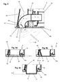
- FIG. 3 shows the dotted framed section d FIG. 1 in a detail enlargement and FIG. 4 the in FIG. 2 with e designated area.
- FIGS. 3 and 4 illustrate the special relative positioning of the engine air outlet 23 in relation to the exhaust outlet 17.
- the exhaust outlet 17 is disposed at the height of the side wall 10a within the engine air outlet 23 or the engine air outlet 23 surrounds the exhaust outlet 17 annularly in the exit plane of engine air and exhaust gas from the road milling 1.
- Both the exhaust gas outlet 17 and the engine air outlet 23 formed by the side wall 10a terminate flush with the outer surface of the side wall 10a in the vertical direction or are free of projections with respect to the side wall 10a. Characterized in that exhaust gas and engine air are led out immediately adjacent to each other from the road milling machine 1, a rapid mixing of exhaust gas and engine air occurs, whereby the exhaust gases outside the road milling machine 1 are diluted and cooled.
- the engine air flows in particular in the region of the Ableitraums 16 on the outer surface of the exhaust line 15 or concrete of the manifold 20 along, thereby already a pre-cooling of the exhaust gas takes place in this region of the manifold 20.
- the manifold 20 has a 9 ° bend in the horizontal plane and deflects the inflowing exhaust gas from an orientation directed in the working direction a perpendicular to a lateral orientation.
- the discharge space 16 thus connects fluidically directly to the engine compartment 3 and is defined by an engine compartment wall and a boundary plate 26, which delimits the space between the connection opening 22 and the engine air outlet 23 to the outside and the interior of the machine to a defined guidance of the engine air from the engine compartment 3 to reach the engine air outlet 23 out.
- a central feature of the road milling machine 1 is that active turbulence between the exhaust gas and engine air outside the road milling machine 1 is brought about.
- a swirling device 24 in the form of a bulge in the exhaust pipe of the manifold 20 is provided to the interior of the exhaust pipe. This causes a deflection of the exhaust gas flowing into the notch 25 from its direction of flow, which ultimately results in an interruption of the flow characteristics of the exhaust gases, which are virtually laminar as far as the turbulizer 24, leading to turbulent flow properties.
- the exhaust gases no longer leave the exhaust gas outlet 17 almost straight-line and perpendicularly away from the side wall 10a, but rather turbulently and mix particularly well with the engine air flowing out via the engine air outlet 23 adjacent thereto.
- FIG. 5 Finally, an alternative embodiment of the swirling device 24.
- a baffle 27 is disposed in the flow region of the exhaust gas within the manifold 20.
- the guide plate 27 is inserted obliquely into the flow channel formed by the manifold 20.
- the baffle 27 is directed away from the side wall 10 a and around an axis circumferential exhaust vortex 28 is obtained, which is targeted in addition to the mixing with engine air from the engine air outlet 23 away from the side wall 10 a in the whirling direction X.
- the exhaust gas-engine air mixture is deliberately led away from the side wall 10a of the road milling machine 1, so that, in particular, sooting phenomena on the side wall 10a can be particularly well prevented with this variant.
- a supplementary turbulence device for example a guide plate
- the driving force for the forced turbulence of exhaust gas and engine air can thus be achieved both via a turbulence device via the exhaust gas outlet 17 and in addition or alternatively via the engine air outlet 23.
- FIGS. 6a to 6c illustrate what in the present invention of the term “substantially flush” with respect to the conclusion of the exhaust outlet 17 and the outer surface of the outer wall, specifically the side wall 10a, is included.
- the essential reference variable here is the diameter D of the exhaust pipe of the exhaust manifold 20 in the region of the exhaust gas outlet 17.
- the exhaust gas outlet 17 and / or the engine air outlet 23 are returned to the engine in a limited area, specifically within a range of up to a maximum of half the diameter D of the exhaust gas outlet 17, relative to the outer surface of the side wall 10a are or project outward.
- the diameter D is the pipe diameter of the exhaust manifold 20 in the region of the exhaust gas outlet 17.
- the exhaust outlet 17 is set back by the amount A into the interior of the machine relative to the outer surface of the side wall 10a.
- the offset A is the distance between the exhaust outlet 17 and the outer surface of the side wall 10a perpendicular to the adjacent to the exhaust outlet 17 and the engine air outlet 23 side wall 10a.
- the offset A is maximum D / 2.
- Fig. 6c the situation illustrates when the exhaust gas outlet 17 protrudes outwardly beyond the outer surface of the side wall 10a adjacent to the exhaust gas outlet 17 and the engine air outlet 23, respectively.
- a maximum supernatant A of D / 2 is included.
- the offset A is determined perpendicular to the outer surface of the side wall 10a adjacent to the exhaust gas outlet 17 or engine air outlet 23.
Landscapes
- Engineering & Computer Science (AREA)
- Chemical & Material Sciences (AREA)
- Combustion & Propulsion (AREA)
- Mechanical Engineering (AREA)
- General Engineering & Computer Science (AREA)
- Transportation (AREA)
- Exhaust Gas After Treatment (AREA)
- Exhaust Silencers (AREA)
- Road Paving Machines (AREA)
Applications Claiming Priority (1)
| Application Number | Priority Date | Filing Date | Title |
|---|---|---|---|
| DE201110114709 DE102011114709A1 (de) | 2011-09-30 | 2011-09-30 | Abgasführung für eine Baumaschine, insbesondere für eine Straßenfräse |
Publications (3)
| Publication Number | Publication Date |
|---|---|
| EP2574751A2 true EP2574751A2 (fr) | 2013-04-03 |
| EP2574751A3 EP2574751A3 (fr) | 2015-06-17 |
| EP2574751B1 EP2574751B1 (fr) | 2017-11-29 |
Family
ID=46982331
Family Applications (1)
| Application Number | Title | Priority Date | Filing Date |
|---|---|---|---|
| EP12006684.0A Not-in-force EP2574751B1 (fr) | 2011-09-30 | 2012-09-25 | Conduit de gaz d'échappement pour une fraiseuse à froid pour asphalte |
Country Status (4)
| Country | Link |
|---|---|
| US (1) | US9162563B2 (fr) |
| EP (1) | EP2574751B1 (fr) |
| CN (1) | CN103075235B (fr) |
| DE (1) | DE102011114709A1 (fr) |
Cited By (1)
| Publication number | Priority date | Publication date | Assignee | Title |
|---|---|---|---|---|
| EP3966439A1 (fr) * | 2019-05-08 | 2022-03-16 | Rior, Industrie- en Handelsonderneming B.V. | Moteur de service avec refroidissement d'échappement |
Families Citing this family (6)
| Publication number | Priority date | Publication date | Assignee | Title |
|---|---|---|---|---|
| JP6317458B2 (ja) * | 2013-10-16 | 2018-04-25 | ロードテック,インコーポレーテッド | 粉塵の排出を制御する方法及び装置 |
| US9302579B2 (en) | 2014-05-20 | 2016-04-05 | Deere & Company | Flush mounted tractor exhaust outlet |
| CN112031906B (zh) * | 2020-08-11 | 2021-09-21 | 东风商用车有限公司 | 一种危化品车排气尾管 |
| CN112177750A (zh) * | 2020-09-30 | 2021-01-05 | 江苏徐工工程机械研究院有限公司 | 一种具有排气引射冷却装置的工程车辆冷却系统 |
| DE102021108113B4 (de) * | 2021-03-30 | 2025-01-09 | Wirtgen Gmbh | Selbstfahrende Bodenbearbeitungsmaschine mit kombinierter Wärmetauscher-Kühlung und Motorraumentlüftung |
| US12054892B2 (en) | 2021-08-24 | 2024-08-06 | Bryce Wuori | Dielectric profile exhaust drying system |
Citations (1)
| Publication number | Priority date | Publication date | Assignee | Title |
|---|---|---|---|---|
| DE102010014529A1 (de) | 2010-04-10 | 2011-10-13 | Bomag Gmbh | Baumaschine zum Bearbeiten einer Fahrbahnoberfläche |
Family Cites Families (9)
| Publication number | Priority date | Publication date | Assignee | Title |
|---|---|---|---|---|
| JPS61105229U (fr) * | 1984-12-18 | 1986-07-04 | ||
| US5857324A (en) * | 1995-12-14 | 1999-01-12 | Scappatura; Dominic E. | Internal combustion engine exhaust treating apparatus and method |
| JPH11257045A (ja) * | 1998-03-13 | 1999-09-21 | Hitachi Constr Mach Co Ltd | 建設機械の排気装置 |
| JP4139522B2 (ja) * | 1999-06-18 | 2008-08-27 | ヤンマー株式会社 | エンジン排気ガスの拡散構造 |
| JP4160454B2 (ja) * | 2003-06-23 | 2008-10-01 | 新キャタピラー三菱株式会社 | 建設機械のエンジンフード,建設機械のエンジンルーム構造及び建設機械のエンジン冷却装置 |
| CN2869342Y (zh) * | 2005-12-27 | 2007-02-14 | 三一重工股份有限公司 | 铣刨机冷却风扇的控制装置 |
| US20080115989A1 (en) * | 2006-11-20 | 2008-05-22 | Matte Francois | Diesel engine vehicle configurations for evacuation of engine and/or exhaust system heat |
| JP2010116122A (ja) * | 2008-11-14 | 2010-05-27 | Sumitomo (Shi) Construction Machinery Co Ltd | エンジンの排気消音装置 |
| KR20100061875A (ko) * | 2008-12-01 | 2010-06-10 | 볼보 컨스트럭션 이키프먼트 홀딩 스웨덴 에이비 | 건설기계용 배기가스 저온화 장치 |
-
2011
- 2011-09-30 DE DE201110114709 patent/DE102011114709A1/de not_active Withdrawn
-
2012
- 2012-09-25 EP EP12006684.0A patent/EP2574751B1/fr not_active Not-in-force
- 2012-09-26 US US13/626,975 patent/US9162563B2/en not_active Expired - Fee Related
- 2012-09-29 CN CN201210597924.5A patent/CN103075235B/zh not_active Expired - Fee Related
Patent Citations (1)
| Publication number | Priority date | Publication date | Assignee | Title |
|---|---|---|---|---|
| DE102010014529A1 (de) | 2010-04-10 | 2011-10-13 | Bomag Gmbh | Baumaschine zum Bearbeiten einer Fahrbahnoberfläche |
Cited By (2)
| Publication number | Priority date | Publication date | Assignee | Title |
|---|---|---|---|---|
| EP3966439A1 (fr) * | 2019-05-08 | 2022-03-16 | Rior, Industrie- en Handelsonderneming B.V. | Moteur de service avec refroidissement d'échappement |
| EP3966439B1 (fr) * | 2019-05-08 | 2025-09-17 | Rior, Industrie- en Handelsonderneming B.V. | Véhicule de service avec moteur et refroidissement d'échappement |
Also Published As
| Publication number | Publication date |
|---|---|
| EP2574751B1 (fr) | 2017-11-29 |
| US9162563B2 (en) | 2015-10-20 |
| US20130081898A1 (en) | 2013-04-04 |
| DE102011114709A1 (de) | 2013-04-04 |
| CN103075235A (zh) | 2013-05-01 |
| CN103075235B (zh) | 2017-04-26 |
| EP2574751A3 (fr) | 2015-06-17 |
Similar Documents
| Publication | Publication Date | Title |
|---|---|---|
| EP2574751B1 (fr) | Conduit de gaz d'échappement pour une fraiseuse à froid pour asphalte | |
| DE10235192A1 (de) | Kühlsystem für Fahrzeuge und Verfahren zum Steuern mindestens eines einen Kühler durchströmenden Luftmassenstroms | |
| DE3825071C1 (fr) | ||
| EP2269852B1 (fr) | Véhicule automobile et toit ouvrant pour un véhicule automobile | |
| EP1753943B1 (fr) | Systeme de refroidissement | |
| DE3322338C2 (fr) | ||
| DE102011051489B4 (de) | Gebläse-Luftansaugungsvorrichtung | |
| EP2479398B1 (fr) | Finisseur de route ou chargeur | |
| EP2236837A2 (fr) | Ventilateur axial, en particulier pour un véhicule automobile | |
| EP2269853A1 (fr) | Véhicule automobile avec déflecteur | |
| EP2316677B1 (fr) | Aérateur | |
| DE202014101664U1 (de) | Schutz zur Reduzierung von Abgasruss- und Kondensatablagerung | |
| DE102013223105A1 (de) | In KFZ-Träger integrierte Gas-, insbesondere Luftleitvorrichtung | |
| DE102020103196A1 (de) | Kraftfahrzeug mit einer im Heckbereich vorgesehenen Unterbodenverkleidung | |
| DE102006061826A1 (de) | Einlasssystem eines Fahrzeugmotors | |
| DE10211591B4 (de) | Luftheizgerät zur Integration in eine luftführende Gehäuseanordnung | |
| DE102015205414B3 (de) | Kühlerlüfteranordnung eingerichtet für ein Kühlsystem eines flüssigkeitsgekühlten Motors eines Fahrzeugs | |
| DE102004010632A1 (de) | Kraftfahrzeug mit doppeltem Kühler | |
| EP4127483B1 (fr) | Ventilateur à jet pour la ventilation de tunnels, système de ventilateur à jet et procédé | |
| DE19734498A1 (de) | Abgasführung für ein Fahrzeug | |
| DE102005001959A1 (de) | Kühlluftführung eines in einem Motorraum angeordneten Verbrennungsmotors einer Sattelzugmaschine | |
| EP3172425B1 (fr) | Module d'aspiration pourvu d'une recirculation de gaz d'échappement intégrée pour moteur à combustion interne | |
| EP1382512A2 (fr) | Arrangement de conduits d'air pour un plancher de véhicule | |
| EP0665379A1 (fr) | Support d'une pompe avec refroidisseur d'huile intégré | |
| EP2154011A1 (fr) | Climatisation équipée d'un ventilateur, notamment dans un engin ou une machine agricole |
Legal Events
| Date | Code | Title | Description |
|---|---|---|---|
| PUAI | Public reference made under article 153(3) epc to a published international application that has entered the european phase |
Free format text: ORIGINAL CODE: 0009012 |
|
| AK | Designated contracting states |
Kind code of ref document: A2 Designated state(s): AL AT BE BG CH CY CZ DE DK EE ES FI FR GB GR HR HU IE IS IT LI LT LU LV MC MK MT NL NO PL PT RO RS SE SI SK SM TR |
|
| AX | Request for extension of the european patent |
Extension state: BA ME |
|
| PUAL | Search report despatched |
Free format text: ORIGINAL CODE: 0009013 |
|
| AK | Designated contracting states |
Kind code of ref document: A3 Designated state(s): AL AT BE BG CH CY CZ DE DK EE ES FI FR GB GR HR HU IE IS IT LI LT LU LV MC MK MT NL NO PL PT RO RS SE SI SK SM TR |
|
| AX | Request for extension of the european patent |
Extension state: BA ME |
|
| RIC1 | Information provided on ipc code assigned before grant |
Ipc: F01N 13/18 20100101ALI20150508BHEP Ipc: F01N 3/28 20060101ALI20150508BHEP Ipc: F01N 3/30 20060101ALI20150508BHEP Ipc: B60K 13/04 20060101ALI20150508BHEP Ipc: F01N 13/08 20100101ALI20150508BHEP Ipc: F01N 3/32 20060101AFI20150508BHEP Ipc: B60K 11/06 20060101ALI20150508BHEP |
|
| 17P | Request for examination filed |
Effective date: 20151118 |
|
| RBV | Designated contracting states (corrected) |
Designated state(s): AL AT BE BG CH CY CZ DE DK EE ES FI FR GB GR HR HU IE IS IT LI LT LU LV MC MK MT NL NO PL PT RO RS SE SI SK SM TR |
|
| 17Q | First examination report despatched |
Effective date: 20161026 |
|
| GRAP | Despatch of communication of intention to grant a patent |
Free format text: ORIGINAL CODE: EPIDOSNIGR1 |
|
| INTG | Intention to grant announced |
Effective date: 20170719 |
|
| GRAS | Grant fee paid |
Free format text: ORIGINAL CODE: EPIDOSNIGR3 |
|
| GRAA | (expected) grant |
Free format text: ORIGINAL CODE: 0009210 |
|
| AK | Designated contracting states |
Kind code of ref document: B1 Designated state(s): AL AT BE BG CH CY CZ DE DK EE ES FI FR GB GR HR HU IE IS IT LI LT LU LV MC MK MT NL NO PL PT RO RS SE SI SK SM TR |
|
| REG | Reference to a national code |
Ref country code: CH Ref legal event code: EP |
|
| REG | Reference to a national code |
Ref country code: AT Ref legal event code: REF Ref document number: 950607 Country of ref document: AT Kind code of ref document: T Effective date: 20171215 |
|
| REG | Reference to a national code |
Ref country code: IE Ref legal event code: FG4D Free format text: LANGUAGE OF EP DOCUMENT: GERMAN |
|
| REG | Reference to a national code |
Ref country code: DE Ref legal event code: R096 Ref document number: 502012011712 Country of ref document: DE |
|
| REG | Reference to a national code |
Ref country code: NL Ref legal event code: MP Effective date: 20171129 |
|
| REG | Reference to a national code |
Ref country code: LT Ref legal event code: MG4D |
|
| PG25 | Lapsed in a contracting state [announced via postgrant information from national office to epo] |
Ref country code: LT Free format text: LAPSE BECAUSE OF FAILURE TO SUBMIT A TRANSLATION OF THE DESCRIPTION OR TO PAY THE FEE WITHIN THE PRESCRIBED TIME-LIMIT Effective date: 20171129 Ref country code: SE Free format text: LAPSE BECAUSE OF FAILURE TO SUBMIT A TRANSLATION OF THE DESCRIPTION OR TO PAY THE FEE WITHIN THE PRESCRIBED TIME-LIMIT Effective date: 20171129 Ref country code: NO Free format text: LAPSE BECAUSE OF FAILURE TO SUBMIT A TRANSLATION OF THE DESCRIPTION OR TO PAY THE FEE WITHIN THE PRESCRIBED TIME-LIMIT Effective date: 20180228 Ref country code: ES Free format text: LAPSE BECAUSE OF FAILURE TO SUBMIT A TRANSLATION OF THE DESCRIPTION OR TO PAY THE FEE WITHIN THE PRESCRIBED TIME-LIMIT Effective date: 20171129 Ref country code: FI Free format text: LAPSE BECAUSE OF FAILURE TO SUBMIT A TRANSLATION OF THE DESCRIPTION OR TO PAY THE FEE WITHIN THE PRESCRIBED TIME-LIMIT Effective date: 20171129 |
|
| PG25 | Lapsed in a contracting state [announced via postgrant information from national office to epo] |
Ref country code: BG Free format text: LAPSE BECAUSE OF FAILURE TO SUBMIT A TRANSLATION OF THE DESCRIPTION OR TO PAY THE FEE WITHIN THE PRESCRIBED TIME-LIMIT Effective date: 20180228 Ref country code: GR Free format text: LAPSE BECAUSE OF FAILURE TO SUBMIT A TRANSLATION OF THE DESCRIPTION OR TO PAY THE FEE WITHIN THE PRESCRIBED TIME-LIMIT Effective date: 20180301 Ref country code: RS Free format text: LAPSE BECAUSE OF FAILURE TO SUBMIT A TRANSLATION OF THE DESCRIPTION OR TO PAY THE FEE WITHIN THE PRESCRIBED TIME-LIMIT Effective date: 20171129 Ref country code: LV Free format text: LAPSE BECAUSE OF FAILURE TO SUBMIT A TRANSLATION OF THE DESCRIPTION OR TO PAY THE FEE WITHIN THE PRESCRIBED TIME-LIMIT Effective date: 20171129 Ref country code: HR Free format text: LAPSE BECAUSE OF FAILURE TO SUBMIT A TRANSLATION OF THE DESCRIPTION OR TO PAY THE FEE WITHIN THE PRESCRIBED TIME-LIMIT Effective date: 20171129 |
|
| PG25 | Lapsed in a contracting state [announced via postgrant information from national office to epo] |
Ref country code: NL Free format text: LAPSE BECAUSE OF FAILURE TO SUBMIT A TRANSLATION OF THE DESCRIPTION OR TO PAY THE FEE WITHIN THE PRESCRIBED TIME-LIMIT Effective date: 20171129 |
|
| PG25 | Lapsed in a contracting state [announced via postgrant information from national office to epo] |
Ref country code: SK Free format text: LAPSE BECAUSE OF FAILURE TO SUBMIT A TRANSLATION OF THE DESCRIPTION OR TO PAY THE FEE WITHIN THE PRESCRIBED TIME-LIMIT Effective date: 20171129 Ref country code: EE Free format text: LAPSE BECAUSE OF FAILURE TO SUBMIT A TRANSLATION OF THE DESCRIPTION OR TO PAY THE FEE WITHIN THE PRESCRIBED TIME-LIMIT Effective date: 20171129 Ref country code: CY Free format text: LAPSE BECAUSE OF FAILURE TO SUBMIT A TRANSLATION OF THE DESCRIPTION OR TO PAY THE FEE WITHIN THE PRESCRIBED TIME-LIMIT Effective date: 20171129 Ref country code: CZ Free format text: LAPSE BECAUSE OF FAILURE TO SUBMIT A TRANSLATION OF THE DESCRIPTION OR TO PAY THE FEE WITHIN THE PRESCRIBED TIME-LIMIT Effective date: 20171129 Ref country code: DK Free format text: LAPSE BECAUSE OF FAILURE TO SUBMIT A TRANSLATION OF THE DESCRIPTION OR TO PAY THE FEE WITHIN THE PRESCRIBED TIME-LIMIT Effective date: 20171129 |
|
| REG | Reference to a national code |
Ref country code: DE Ref legal event code: R097 Ref document number: 502012011712 Country of ref document: DE |
|
| PG25 | Lapsed in a contracting state [announced via postgrant information from national office to epo] |
Ref country code: SM Free format text: LAPSE BECAUSE OF FAILURE TO SUBMIT A TRANSLATION OF THE DESCRIPTION OR TO PAY THE FEE WITHIN THE PRESCRIBED TIME-LIMIT Effective date: 20171129 Ref country code: PL Free format text: LAPSE BECAUSE OF FAILURE TO SUBMIT A TRANSLATION OF THE DESCRIPTION OR TO PAY THE FEE WITHIN THE PRESCRIBED TIME-LIMIT Effective date: 20171129 Ref country code: IT Free format text: LAPSE BECAUSE OF FAILURE TO SUBMIT A TRANSLATION OF THE DESCRIPTION OR TO PAY THE FEE WITHIN THE PRESCRIBED TIME-LIMIT Effective date: 20171129 Ref country code: RO Free format text: LAPSE BECAUSE OF FAILURE TO SUBMIT A TRANSLATION OF THE DESCRIPTION OR TO PAY THE FEE WITHIN THE PRESCRIBED TIME-LIMIT Effective date: 20171129 |
|
| PG25 | Lapsed in a contracting state [announced via postgrant information from national office to epo] |
Ref country code: MT Free format text: LAPSE BECAUSE OF FAILURE TO SUBMIT A TRANSLATION OF THE DESCRIPTION OR TO PAY THE FEE WITHIN THE PRESCRIBED TIME-LIMIT Effective date: 20171129 |
|
| PLBE | No opposition filed within time limit |
Free format text: ORIGINAL CODE: 0009261 |
|
| STAA | Information on the status of an ep patent application or granted ep patent |
Free format text: STATUS: NO OPPOSITION FILED WITHIN TIME LIMIT |
|
| 26N | No opposition filed |
Effective date: 20180830 |
|
| PG25 | Lapsed in a contracting state [announced via postgrant information from national office to epo] |
Ref country code: SI Free format text: LAPSE BECAUSE OF FAILURE TO SUBMIT A TRANSLATION OF THE DESCRIPTION OR TO PAY THE FEE WITHIN THE PRESCRIBED TIME-LIMIT Effective date: 20171129 |
|
| PG25 | Lapsed in a contracting state [announced via postgrant information from national office to epo] |
Ref country code: MC Free format text: LAPSE BECAUSE OF FAILURE TO SUBMIT A TRANSLATION OF THE DESCRIPTION OR TO PAY THE FEE WITHIN THE PRESCRIBED TIME-LIMIT Effective date: 20171129 |
|
| REG | Reference to a national code |
Ref country code: CH Ref legal event code: PL |
|
| GBPC | Gb: european patent ceased through non-payment of renewal fee |
Effective date: 20180925 |
|
| REG | Reference to a national code |
Ref country code: BE Ref legal event code: MM Effective date: 20180930 |
|
| REG | Reference to a national code |
Ref country code: IE Ref legal event code: MM4A |
|
| PG25 | Lapsed in a contracting state [announced via postgrant information from national office to epo] |
Ref country code: LU Free format text: LAPSE BECAUSE OF NON-PAYMENT OF DUE FEES Effective date: 20180925 |
|
| PG25 | Lapsed in a contracting state [announced via postgrant information from national office to epo] |
Ref country code: IE Free format text: LAPSE BECAUSE OF NON-PAYMENT OF DUE FEES Effective date: 20180925 |
|
| PG25 | Lapsed in a contracting state [announced via postgrant information from national office to epo] |
Ref country code: BE Free format text: LAPSE BECAUSE OF NON-PAYMENT OF DUE FEES Effective date: 20180930 Ref country code: FR Free format text: LAPSE BECAUSE OF NON-PAYMENT OF DUE FEES Effective date: 20180930 Ref country code: LI Free format text: LAPSE BECAUSE OF NON-PAYMENT OF DUE FEES Effective date: 20180930 Ref country code: CH Free format text: LAPSE BECAUSE OF NON-PAYMENT OF DUE FEES Effective date: 20180930 |
|
| PG25 | Lapsed in a contracting state [announced via postgrant information from national office to epo] |
Ref country code: GB Free format text: LAPSE BECAUSE OF NON-PAYMENT OF DUE FEES Effective date: 20180925 |
|
| REG | Reference to a national code |
Ref country code: AT Ref legal event code: MM01 Ref document number: 950607 Country of ref document: AT Kind code of ref document: T Effective date: 20180925 |
|
| PG25 | Lapsed in a contracting state [announced via postgrant information from national office to epo] |
Ref country code: AT Free format text: LAPSE BECAUSE OF NON-PAYMENT OF DUE FEES Effective date: 20180925 |
|
| PG25 | Lapsed in a contracting state [announced via postgrant information from national office to epo] |
Ref country code: TR Free format text: LAPSE BECAUSE OF FAILURE TO SUBMIT A TRANSLATION OF THE DESCRIPTION OR TO PAY THE FEE WITHIN THE PRESCRIBED TIME-LIMIT Effective date: 20171129 |
|
| PG25 | Lapsed in a contracting state [announced via postgrant information from national office to epo] |
Ref country code: HU Free format text: LAPSE BECAUSE OF FAILURE TO SUBMIT A TRANSLATION OF THE DESCRIPTION OR TO PAY THE FEE WITHIN THE PRESCRIBED TIME-LIMIT; INVALID AB INITIO Effective date: 20120925 Ref country code: PT Free format text: LAPSE BECAUSE OF FAILURE TO SUBMIT A TRANSLATION OF THE DESCRIPTION OR TO PAY THE FEE WITHIN THE PRESCRIBED TIME-LIMIT Effective date: 20171129 |
|
| PG25 | Lapsed in a contracting state [announced via postgrant information from national office to epo] |
Ref country code: MK Free format text: LAPSE BECAUSE OF NON-PAYMENT OF DUE FEES Effective date: 20171129 |
|
| PG25 | Lapsed in a contracting state [announced via postgrant information from national office to epo] |
Ref country code: AL Free format text: LAPSE BECAUSE OF FAILURE TO SUBMIT A TRANSLATION OF THE DESCRIPTION OR TO PAY THE FEE WITHIN THE PRESCRIBED TIME-LIMIT Effective date: 20171129 Ref country code: IS Free format text: LAPSE BECAUSE OF FAILURE TO SUBMIT A TRANSLATION OF THE DESCRIPTION OR TO PAY THE FEE WITHIN THE PRESCRIBED TIME-LIMIT Effective date: 20180329 |
|
| P01 | Opt-out of the competence of the unified patent court (upc) registered |
Effective date: 20230527 |
|
| REG | Reference to a national code |
Ref country code: DE Ref legal event code: R082 Ref document number: 502012011712 Country of ref document: DE Representative=s name: ZIMMERMANN & PARTNER PATENTANWAELTE MBB, DE |
|
| PGFP | Annual fee paid to national office [announced via postgrant information from national office to epo] |
Ref country code: DE Payment date: 20230919 Year of fee payment: 12 |
|
| REG | Reference to a national code |
Ref country code: DE Ref legal event code: R119 Ref document number: 502012011712 Country of ref document: DE |
|
| PG25 | Lapsed in a contracting state [announced via postgrant information from national office to epo] |
Ref country code: DE Free format text: LAPSE BECAUSE OF NON-PAYMENT OF DUE FEES Effective date: 20250401 |