EP2574790A1 - System zur Abgabe von Grundierungsflüssigkeit für eine Unterseepumpe oder einen Unterseekompressor - Google Patents
System zur Abgabe von Grundierungsflüssigkeit für eine Unterseepumpe oder einen Unterseekompressor Download PDFInfo
- Publication number
- EP2574790A1 EP2574790A1 EP11007995A EP11007995A EP2574790A1 EP 2574790 A1 EP2574790 A1 EP 2574790A1 EP 11007995 A EP11007995 A EP 11007995A EP 11007995 A EP11007995 A EP 11007995A EP 2574790 A1 EP2574790 A1 EP 2574790A1
- Authority
- EP
- European Patent Office
- Prior art keywords
- pump
- rotor
- priming liquid
- compressor
- liquid
- Prior art date
- Legal status (The legal status is an assumption and is not a legal conclusion. Google has not performed a legal analysis and makes no representation as to the accuracy of the status listed.)
- Withdrawn
Links
Images

Classifications
-
- F—MECHANICAL ENGINEERING; LIGHTING; HEATING; WEAPONS; BLASTING
- F04—POSITIVE - DISPLACEMENT MACHINES FOR LIQUIDS; PUMPS FOR LIQUIDS OR ELASTIC FLUIDS
- F04C—ROTARY-PISTON, OR OSCILLATING-PISTON, POSITIVE-DISPLACEMENT MACHINES FOR LIQUIDS; ROTARY-PISTON, OR OSCILLATING-PISTON, POSITIVE-DISPLACEMENT PUMPS
- F04C2/00—Rotary-piston machines or pumps
- F04C2/08—Rotary-piston machines or pumps of intermeshing-engagement type, i.e. with engagement of co-operating members similar to that of toothed gearing
- F04C2/12—Rotary-piston machines or pumps of intermeshing-engagement type, i.e. with engagement of co-operating members similar to that of toothed gearing of other than internal-axis type
- F04C2/14—Rotary-piston machines or pumps of intermeshing-engagement type, i.e. with engagement of co-operating members similar to that of toothed gearing of other than internal-axis type with toothed rotary pistons
- F04C2/16—Rotary-piston machines or pumps of intermeshing-engagement type, i.e. with engagement of co-operating members similar to that of toothed gearing of other than internal-axis type with toothed rotary pistons with helical teeth, e.g. chevron-shaped, screw type
-
- F—MECHANICAL ENGINEERING; LIGHTING; HEATING; WEAPONS; BLASTING
- F04—POSITIVE - DISPLACEMENT MACHINES FOR LIQUIDS; PUMPS FOR LIQUIDS OR ELASTIC FLUIDS
- F04C—ROTARY-PISTON, OR OSCILLATING-PISTON, POSITIVE-DISPLACEMENT MACHINES FOR LIQUIDS; ROTARY-PISTON, OR OSCILLATING-PISTON, POSITIVE-DISPLACEMENT PUMPS
- F04C13/00—Adaptations of machines or pumps for special use, e.g. for extremely high pressures
- F04C13/008—Pumps for submersible use, i.e. down-hole pumping
-
- F—MECHANICAL ENGINEERING; LIGHTING; HEATING; WEAPONS; BLASTING
- F04—POSITIVE - DISPLACEMENT MACHINES FOR LIQUIDS; PUMPS FOR LIQUIDS OR ELASTIC FLUIDS
- F04C—ROTARY-PISTON, OR OSCILLATING-PISTON, POSITIVE-DISPLACEMENT MACHINES FOR LIQUIDS; ROTARY-PISTON, OR OSCILLATING-PISTON, POSITIVE-DISPLACEMENT PUMPS
- F04C15/00—Component parts, details or accessories of machines, pumps or pumping installations, not provided for in groups F04C2/00 - F04C14/00
- F04C15/0096—Heating; Cooling
-
- F—MECHANICAL ENGINEERING; LIGHTING; HEATING; WEAPONS; BLASTING
- F04—POSITIVE - DISPLACEMENT MACHINES FOR LIQUIDS; PUMPS FOR LIQUIDS OR ELASTIC FLUIDS
- F04C—ROTARY-PISTON, OR OSCILLATING-PISTON, POSITIVE-DISPLACEMENT MACHINES FOR LIQUIDS; ROTARY-PISTON, OR OSCILLATING-PISTON, POSITIVE-DISPLACEMENT PUMPS
- F04C2240/00—Components
- F04C2240/20—Rotors
-
- F—MECHANICAL ENGINEERING; LIGHTING; HEATING; WEAPONS; BLASTING
- F04—POSITIVE - DISPLACEMENT MACHINES FOR LIQUIDS; PUMPS FOR LIQUIDS OR ELASTIC FLUIDS
- F04C—ROTARY-PISTON, OR OSCILLATING-PISTON, POSITIVE-DISPLACEMENT MACHINES FOR LIQUIDS; ROTARY-PISTON, OR OSCILLATING-PISTON, POSITIVE-DISPLACEMENT PUMPS
- F04C2240/00—Components
- F04C2240/60—Shafts
- F04C2240/603—Shafts with internal channels for fluid distribution, e.g. hollow shaft
Definitions
- the present invention refers to arrangements in a pump or compressor which is operated in sub-sea processes for transport and pressure increase of process fluids, and more specifically to a system by which liquid can be supplied to the sub-sea pump or compressor for priming and/or for rotor cooling purposes.
- Pumps and compressors are commonly used in extraction of oil and gas from sub-sea wells to effect transportation or pressure increase in a production fluid.
- the production fluid is in many cases a multiphase fluid containing varying fractions of liquid and gas.
- Pumps and compressors may also be used sub-sea for transport and pressure increase of other process fluid than production fluid, or sea-water.
- twin screw pumps are widely used.
- the twin screw pump is a rotary machine comprising two rotors having intermeshing threads which are driven in rotation by a motor to transfer, by positive displacement, fluid or fluid mixtures in the axial directions of the pump.
- the rotors are housed in a pump chamber defined through a rotor liner or rotor housing, which encases the rotors with a radial clearance between the rotors and the rotor housing.
- the radial width of the clearance is a compromise between sufficient spacing to accommodate for thermal expansion in the rotors without undue loss of efficiency and pressure caused by slippage of gas or liquid at the clearance.
- the pump may suffer from slippage and over-heating caused by dry running.
- both solutions suffer from the fact that priming liquid pressure and flow is dependent on operation of the pump, i.e. dependent on rotation of pump rotors, which may lead to insufficient lubrication during start-up and shut-down. Also, both solutions suffer from a limited volume of priming liquid which may lead to insufficient lubrication and cooling of motor and pump components during high GVF operation for a longer time.
- the present invention aims at avoiding the drawbacks associated with the prior art solutions.
- a priming liquid supply system for a sub-sea pump or compressor having at least one externally threaded rotor that is driven and journalled for rotation in a pump or compressor chamber, wherein an external and pressurized volume of liquid is arranged in flow communication with the pump or compressor chamber via a feed line through which liquid is instantly available for injection into the pump or compressor chamber for priming and/or cooling purposes by control of an on/off switching mechanism arranged on the feed line.
- the invention thus teaches injection of priming liquid from an external source which is maintained under pressure independently of the operational status of a pump or compressor.
- priming liquid flow is instantly available by operation of an on/off switching mechanism. Switching may be accomplished through an electrically controlled one-way valve, optionally connected in series with a non-return valve.
- the priming liquid feed line connects the pump or compressor chamber with a barrier fluid system that is installed at the pump or compressor, and from which priming liquid is extracted and supplied to the pump or compressor chamber, driven by a pressure prevailing in the barrier fluid system.
- priming liquid is supplied to the pump or compressor chamber from a dedicated volume of priming liquid, driven by a pressure applied from a sea- or land-based platform.
- the priming liquid volume is a volume of hydrate prevention fluid included in a hydrate formation prevention system from which priming liquid is extracted and supplied to the pump or compressor chamber, driven by a pressure prevailing in the hydrate formation prevention system.
- priming liquid may be injected into the pump or compressor chamber by a drive pressure which at all times is higher than a detected pumped fluid pressure at the inlet or at the outlet of the pump or compressor.
- Each embodiment of the invention can be configured for recharge, from a sea- or land-based platform, of the volume of liquid that is utilized for priming or cooling purposes.
- Priming liquid can be distributed in the pump or compressor chamber via a system of axial and/or radial channels internally in the pump or compressor rotor(s).
- Priming liquid can be introduced in the internal rotor channel system via a priming liquid feed chamber that is defined between axially spaced fluid seals sealing about the rotor periphery.
- Priming liquid can alternatively be introduced in the internal rotor channel system via a slip ring that is journalled on the rotor for relative rotation and stationary and non-rotationally connected to the pump or compressor structure.
- the internal channel system in the rotor(s) may be configured to include one or more axial supply channels in the rotor body and radial branches in the threads of the rotor(s). At least some of the radial branches may be arranged to mouth in the periphery of the rotor threads, while at least some of the radial branches may be arranged to mouth in one or in both side flanks of the rotor threads. Alternatively, at least some of the radial branches are arranged to mouth in the periphery of the rotor threads and in one or in both side flanks of the rotor threads.
- Non-return valves and/or fixed flow restrictions may be arranged in the internal channel system in the rotor(s).
- the axial supply channels may be arranged with pressure regulators.
- priming liquid is used in the specification and claims to simplify language and shall not be narrowly interpreted, and refers to a liquid that is supplied for any or for the combined purposes of priming, cooling or lubrication of a pump or compressor.
- carrier fluid is used in the specification and claims to simplify language and shall not be narrowly interpreted, and refers to a fluid, typically a liquid, which is supplied for any or for the combined purposes of providing pressure barrier, cooling or lubrication of a pump or compressor.
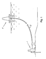
- reference number 1 depicts a pump situated on the sea floor.
- the pump 1 may be driven and operative for pumping hydrocarbon fluid from a sub-sea well to a floating platform 2, or to a land based platform, via a conduit 3.
- the pump may also be used for injecting sea water or process liquid, such as the liquid phase of a multiphase fluid extracted from the sub-sea well, into the sub-sea well for reducing back pressure and assisting in the recovery of hydrocarbon products.
- additional pumps or compressors may be required at other locations along the conduit to assist in transportation of hydrocarbon fluid from the sub-sea well to the platform.
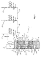
- the pump 1 may be a fixed displacement pump of the twin screw type as depicted in sectional view in Fig. 2 .
- the twin screw pump comprises two rotors 4, 5 which are journalled in bearings 6 for rotation inside a rotor liner or rotor housing 7, the rotor housing radially defining a pump chamber 7' that is axially defined between seals 8.
- the rotors are journalled with a radial clearance 9 between the rotors and the housing.
- Each rotor 4, 5 is formed with two sections of threads 10 and 11 in intermeshing relation with corresponding threaded sections of the opposite rotor.
- the intermeshing threads of rotors 4, 5 effect transportation of discrete volumes of a pumped medium in axial directions of the pump, from pump inlets 12, 13 towards a longitudinal center of the pump from where the pumped fluid is discharged via a pump outlet 14.
- Reverse flow may be accomplished by reverse rotation of the pump rotors.
- the rotors 4, 5 are driven by a motor 15 which is drivingly connected to one of the rotors 4 or 5. Synchronization of the rotors is accomplished by means of a timing gear unit 16 which interconnects the rotors in the ends remote from the motor 15.
- the motor 15 is encased in a motor housing 17.
- barrier fluid may be supplied to the motor casing, to bearings and seals, at a pressure which exceeds the pressure in sea water and in the pumped fluid.
- barrier fluid may be supplied from the barrier fluid system 18 to bearings, seals and timing gears of the pump.
- the barrier fluid is typically a water/glycol mixture or a water-based control fluid that is supplied from the platform or from an intermediate supply of barrier fluid, delivered to the pump via pipes included in a barrier fluid system 18.
- barrier fluid may also fulfill the purpose of cooling and/or lubrication of components which are exposed to mechanical and thermal wear.
- barrier fluid and “barrier fluid system” shall be understood to include a liquid or a system providing pressure barrier and/or lubrication and/or cooling of components in a sub-sea motor and pump or compressor assembly.
- Pressure and flow in a barrier fluid system may be controlled by means of flow control valves, pressure sensors and pressure control devices which are known in the art and typically included in a sub-sea barrier fluid system. Since a skilled person would be familiar with the structure and functionality of sub-sea barrier fluid systems in general and since the art and function of the priming liquid supply system of the present invention is not dependent on a specific layout of the barrier fluid system, a detailed description of barrier fluid systems is not required to explain and understand the present invention.
- the pressure in the barrier fluid system 18 may be related to variations in pressure in the production fluid, and is at all times maintained at a pressure which exceeds the pressure in the pump chamber. Loss of barrier fluid caused by leakage via seals and bearings is compensated for by filling up the barrier fluid system 18 from a supply of barrier fluid on the platform or from a dedicated supply of barrier fluid at the pump location sub-sea.
- priming liquid is extracted and supplied from the barrier fluid system 18 for injection into the pump chamber.
- priming liquid is supplied from a dedicated volume of priming liquid that is set under pressure from the platform.
- priming liquid is extracted and supplied from a volume of hydrate formation prevention fluid, such as methanol or glycol that is set under pressure from the platform.
- a volume of hydrate formation prevention fluid such as methanol or glycol that is set under pressure from the platform.
- Priming liquid is routed to the pump via a priming liquid feed line 19 connecting the pump with the priming liquid volume over an on/off valve 20.
- the on/off valve 20 may be an electromagnetically actuated one-way flow control valve which is controlled from the platform.
- a non-return valve 21 in the priming liquid supply line 19 may be arranged to prevent back flow of priming liquid.
- a throttle valve 22 may optionally be inserted in the priming liquid feed line 19 for flow regulation.
- the priming liquid feed line 19 connects the pump with the barrier fluid system 18, as illustrated by continuous lines in Fig. 2 . Opening the on/off valve 20 provides instant flow of priming liquid driven by a pressure prevailing in the barrier fluid system 18, which can be controlled from the platform and which may optionally be balanced with a detected pumped fluid pressure at the pump inlet or outlet.
- the priming liquid feed line 19 connects the pump with a dedicated volume 23 of priming liquid, as illustrated by broken lines in Fig. 2 . Opening the on/off valve 20 provides instant flow of priming liquid driven by a pressure prevailing in the priming liquid volume 23, which can be controlled from the platform.
- the priming liquid feed line 19 connects the pump with a volume of hydrate prevention fluid in a hydrate formation prevention system 24, as illustrated by dash-dot lines in Fig. 2 . Opening the on/off valve 20 provides instant flow of priming liquid driven by the pressure prevailing in the hydrate formation prevention system, which can be controlled from the platform.
- the feed of priming liquid to the pump is controlled by operation of an on/ off switching mechanism by which the pump chamber can be set in flow communication with a volume of priming liquid that is maintained under pressure.
- injection of priming liquid can be driven by a pressure that is higher than a detected pumped fluid pressure at the inlet or at the outlet of the pump. Flow of priming liquid is this way instantly available for injection into the pump chamber.
- priming liquid can be distributed in various ways.
- priming liquid may advantageously be routed to the clearance 9 via the pump rotor(s).
- the rotors may be designed with an internal channel system that opens in the ends/periphery of the rotor threads, in a way that is known in the art.
- the internal channel system in the rotor(s) then comprises one or more axial supply channels 25 in the rotor body from which channels or branches 26 extend in radial directions to the periphery of the rotor threads.
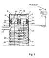
- priming liquid is distributed to the internal channel system 25, 26 of the rotor(s) via a priming liquid feed chamber 27, depicted in Fig. 2 .
- the priming liquid feed chamber 27 is defmed between radial fluid seals 28 and 29 which effect sealing about the rotor axis.
- the fluid seals 28 and 29 are arranged in axially spaced relation in a region between rotor bearings 6 and the nearest threaded section 10 of the rotor(s).
- Priming liquid supplied via the priming liquid feed line 19 enters the priming liquid feed chamber 27 via an opening in the wall of the rotor housing 7. From the priming liquid feed chamber 27, priming liquid is distributed to the one or more axial supply channels 25 in the rotor body via one or more radial feed channels 30 mouthing in the rotor periphery.
- priming liquid is distributed to the internal channel system 25, 26 of a rotor via a slip ring 31.
- the slip ring 31 is journalled on the rotor for relative rotation but is stationary/non-rotationally connected to the pump structure, such as to the rotor housing 7.
- the slip ring 31 is situated on the rotor axis between the rotor bearings 6 and the nearest threaded section 10 of the rotor.
- the slip ring 31 is located in a position where a circumferential recess 32 in the inner periphery of the slip ring is aligned with the mouth or mouths of the one or more radial feed channels 30.
- Ring seals 33 on each side of the recess may be arranged to effect sealing about the rotor axis.
- Priming liquid supplied via the priming liquid feed line 19 enters the circumferential recess 32 via a feed line connection 34 arranged on the exterior of the slip ring.
- each rotor may be associated with a slip ring 31, respectively. In such case, the flow of priming liquid supplied via the priming liquid feed line 19 is divided, inside or outside the rotor housing, into partial flows feeding the slip rings.
- the priming liquid feed chamber 27, as well as the slip ring 31, may optionally be located at either end of the pump. In all cases priming liquid is supplied to the pump rotor(s) via a priming liquid feed chamber or via a slip ring that is positioned axially outside the pump chamber which is delimited axially between the seals 8.
- the priming liquid supply system components do not interfere with the flow paths of production fluid through the pump.
- Figs. 4A-4B depicts different designs at the downstream end of the priming liquid supply circuitry.
- the radial branches 26 of the internal channel system in the rotor open axially in one or in both side flanks of the rotor threads.
- Priming liquid can this way be supplied axially into the spaces between the rotor threads and successively into the clearance 9.
- priming liquid may be supplied at large volumes from an external volume of priming liquid which can be recharged from the platform. This option may be desirable at start-up of the pump, e.g., in order to arrive at normal operating conditions for the pump, motor and bearings.
- At least some of the radial branches 26 of the internal channel system in the rotor open radially in the periphery of the rotor threads. This option may be desirable during operation at high gas volume fractions of the pumped fluid in order to avoid gas slippage, pressure loss and over-heating of the rotor(s).
- a combined radial/axial supply of priming liquid is available if some of the radial branches 26 are arranged to mouth in the periphery of the rotor threads and other radial branches 26 are arranged to mouth in the side flanks of the rotor threads.
- the radial branches 26 may be split in the downstream end into a radial channel length opening in the periphery of the rotor threads and an axial channel length opening in a side flank of the rotor threads.
- priming liquid is then supplied to each one of at least two axial supply channels 25 via two separate priming liquid feed chambers 27, or via two separate slip rings 31.
- the two feed chambers 27, or the two slip rings 31, may each be arranged to feed priming liquid into a group of axial supply channels 25 which supply priming liquid to the radially mouthing or to the axially mouthing branches 26.
- the two feed chambers 27 or slip rings 31 may be located in the same one end of the rotor(s), or in separate ends of the rotor(s).
- priming liquid may be supplied to the pump chamber via nozzle holes through the rotor housing wall.
- the nozzle holes may be connected to the priming liquid feed line 19 outside the pump chamber via a manifold pipe.
- the nozzle holes may be evenly spaced along the length of the pump chamber, and several axial rows of nozzle holes may be spaced about the circumference of the pump chamber.
- Still other possible modifications include the provision of fixed or adjustable orifices/flow restrictions or pressure regulators in the axial supply channel(s) 25, and/or at the downstream end of the priming liquid supply circuitry 25, 26 (such as indicated by reference number 36 in Fig. 4A ) aiming for flow regulation and compensation for pressure drops in the priming liquid supply system that could otherwise cause uneven distribution of priming liquid at different locations in the pump chamber.
Landscapes
- Engineering & Computer Science (AREA)
- Mechanical Engineering (AREA)
- General Engineering & Computer Science (AREA)
- Structures Of Non-Positive Displacement Pumps (AREA)
Priority Applications (1)
| Application Number | Priority Date | Filing Date | Title |
|---|---|---|---|
| EP11007995A EP2574790A1 (de) | 2011-09-30 | 2011-09-30 | System zur Abgabe von Grundierungsflüssigkeit für eine Unterseepumpe oder einen Unterseekompressor |
Applications Claiming Priority (1)
| Application Number | Priority Date | Filing Date | Title |
|---|---|---|---|
| EP11007995A EP2574790A1 (de) | 2011-09-30 | 2011-09-30 | System zur Abgabe von Grundierungsflüssigkeit für eine Unterseepumpe oder einen Unterseekompressor |
Publications (1)
| Publication Number | Publication Date |
|---|---|
| EP2574790A1 true EP2574790A1 (de) | 2013-04-03 |
Family
ID=44862271
Family Applications (1)
| Application Number | Title | Priority Date | Filing Date |
|---|---|---|---|
| EP11007995A Withdrawn EP2574790A1 (de) | 2011-09-30 | 2011-09-30 | System zur Abgabe von Grundierungsflüssigkeit für eine Unterseepumpe oder einen Unterseekompressor |
Country Status (1)
| Country | Link |
|---|---|
| EP (1) | EP2574790A1 (de) |
Cited By (1)
| Publication number | Priority date | Publication date | Assignee | Title |
|---|---|---|---|---|
| WO2015097502A1 (en) * | 2013-12-23 | 2015-07-02 | Vetco Gray Scandinavia As | Method and system for supplying barrier fluid in a subsea motor and pump assembly |
Citations (4)
| Publication number | Priority date | Publication date | Assignee | Title |
|---|---|---|---|---|
| US5624249A (en) | 1993-05-19 | 1997-04-29 | Joh. Heinrich Bornemann Gmbh & Co. Kg | Pumping process for operating a multi-phase screw pump and pump |
| US5738505A (en) | 1995-09-05 | 1998-04-14 | Nuovo Pignone S.P.A. | Perfected twin-screw pump, particularly suitable for the pumping of biphase fluids in a submerged environment |
| WO1998053182A1 (en) * | 1997-05-20 | 1998-11-26 | Westinghouse Government Services Company Llc | Sub-sea pumping system and associated method |
| US5871340A (en) * | 1995-06-05 | 1999-02-16 | Hatton; Gregory John | Apparatus for cooling high-pressure boost high gas-fraction twin-screw pumps |
-
2011
- 2011-09-30 EP EP11007995A patent/EP2574790A1/de not_active Withdrawn
Patent Citations (4)
| Publication number | Priority date | Publication date | Assignee | Title |
|---|---|---|---|---|
| US5624249A (en) | 1993-05-19 | 1997-04-29 | Joh. Heinrich Bornemann Gmbh & Co. Kg | Pumping process for operating a multi-phase screw pump and pump |
| US5871340A (en) * | 1995-06-05 | 1999-02-16 | Hatton; Gregory John | Apparatus for cooling high-pressure boost high gas-fraction twin-screw pumps |
| US5738505A (en) | 1995-09-05 | 1998-04-14 | Nuovo Pignone S.P.A. | Perfected twin-screw pump, particularly suitable for the pumping of biphase fluids in a submerged environment |
| WO1998053182A1 (en) * | 1997-05-20 | 1998-11-26 | Westinghouse Government Services Company Llc | Sub-sea pumping system and associated method |
Cited By (6)
| Publication number | Priority date | Publication date | Assignee | Title |
|---|---|---|---|---|
| WO2015097502A1 (en) * | 2013-12-23 | 2015-07-02 | Vetco Gray Scandinavia As | Method and system for supplying barrier fluid in a subsea motor and pump assembly |
| NO20161020A1 (en) * | 2013-12-23 | 2016-06-16 | Vetco Gray Scandinavia As | Method and system for supplying barrier fluid in a subsea motor and pump assembly |
| GB2535124A (en) * | 2013-12-23 | 2016-08-10 | Vetco Gray Scandinavia As | Method and system for supplying barrier fluid in a subsea motor and pump assembly |
| AU2014372275B2 (en) * | 2013-12-23 | 2017-12-07 | Vetco Gray Scandinavia As | Method and system for supplying barrier fluid in a subsea motor and pump assembly |
| NO343643B1 (en) * | 2013-12-23 | 2019-04-15 | Vetco Gray Scandinavia As | Method and system for supplying barrier fluid in a subsea motor and pump assembly |
| GB2535124B (en) * | 2013-12-23 | 2020-05-06 | Vetco Gray Scandinavia As | Method and system for supplying barrier fluid in a subsea motor and pump assembly |
Similar Documents
| Publication | Publication Date | Title |
|---|---|---|
| US8025157B2 (en) | Power recovery system | |
| CN103097650B (zh) | 海底马达和泵模块的补偿式阻隔和润滑流体压力调控系统 | |
| US8066077B2 (en) | Electrical submersible pump and gas compressor | |
| US5779451A (en) | Power efficient multi-stage twin screw pump | |
| US9482225B2 (en) | Gear pump, pumping apparatus including the same, and aircraft fuel system including gear pump | |
| US5871340A (en) | Apparatus for cooling high-pressure boost high gas-fraction twin-screw pumps | |
| GB2450565A (en) | Pressure boosting apparatus with jet pump, mechanical pump and separator | |
| US20130164152A1 (en) | Differential pressure controlled motor and pump barrier fluids pressure regulation system | |
| KR960004250B1 (ko) | 액체링 펌프 및 그의 작동 방법 | |
| NO343643B1 (en) | Method and system for supplying barrier fluid in a subsea motor and pump assembly | |
| EP2574790A1 (de) | System zur Abgabe von Grundierungsflüssigkeit für eine Unterseepumpe oder einen Unterseekompressor | |
| US20110293441A1 (en) | Multiphase pump flow recirculation system | |
| CN105090058B (zh) | 一种无密封lng潜液泵 | |
| US12546330B2 (en) | Bearing assemblies, apparatuses, devices, systems, and methods including bearings | |
| US2500227A (en) | Liquid pumping unit | |
| RU2433306C1 (ru) | Система и способ регулирования работы мультифазного винтового насоса | |
| WO2019084424A1 (en) | MANAGEMENT OF MULTIPLE FLUIDS WITH CENTRIFUGAL FLOW FILTER SYSTEMS | |
| CN102282374A (zh) | 用于流体输送的机器 | |
| US20220042512A1 (en) | Subsea pump system with process lubricated bearings | |
| US2826148A (en) | Submersible combined centrifugal and jet pump | |
| CN224107319U (zh) | 涡旋膨胀机组件和有机朗肯循环系统 | |
| CN223035353U (zh) | 一种具有油腔调温功能的泵 | |
| CN222479047U (zh) | 一种卧式离心泵及矿山排水系统 | |
| CN104350273A (zh) | 流体动力学装置以及包括所述流体动力学装置的燃料供给系统 | |
| US20250223967A1 (en) | Pump system |
Legal Events
| Date | Code | Title | Description |
|---|---|---|---|
| PUAI | Public reference made under article 153(3) epc to a published international application that has entered the european phase |
Free format text: ORIGINAL CODE: 0009012 |
|
| 17P | Request for examination filed |
Effective date: 20111014 |
|
| AK | Designated contracting states |
Kind code of ref document: A1 Designated state(s): AL AT BE BG CH CY CZ DE DK EE ES FI FR GB GR HR HU IE IS IT LI LT LU LV MC MK MT NL NO PL PT RO RS SE SI SK SM TR |
|
| AX | Request for extension of the european patent |
Extension state: BA ME |
|
| STAA | Information on the status of an ep patent application or granted ep patent |
Free format text: STATUS: THE APPLICATION IS DEEMED TO BE WITHDRAWN |
|
| 18D | Application deemed to be withdrawn |
Effective date: 20150401 |