EP2574810A2 - Unité d'entraînement avec une machine électrique - Google Patents
Unité d'entraînement avec une machine électrique Download PDFInfo
- Publication number
- EP2574810A2 EP2574810A2 EP12186609A EP12186609A EP2574810A2 EP 2574810 A2 EP2574810 A2 EP 2574810A2 EP 12186609 A EP12186609 A EP 12186609A EP 12186609 A EP12186609 A EP 12186609A EP 2574810 A2 EP2574810 A2 EP 2574810A2
- Authority
- EP
- European Patent Office
- Prior art keywords
- coupling
- drive unit
- electric machine
- shaft
- output shaft
- Prior art date
- Legal status (The legal status is an assumption and is not a legal conclusion. Google has not performed a legal analysis and makes no representation as to the accuracy of the status listed.)
- Granted
Links
Images



Classifications
-
- B—PERFORMING OPERATIONS; TRANSPORTING
- B60—VEHICLES IN GENERAL
- B60K—ARRANGEMENT OR MOUNTING OF PROPULSION UNITS OR OF TRANSMISSIONS IN VEHICLES; ARRANGEMENT OR MOUNTING OF PLURAL DIVERSE PRIME-MOVERS IN VEHICLES; AUXILIARY DRIVES FOR VEHICLES; INSTRUMENTATION OR DASHBOARDS FOR VEHICLES; ARRANGEMENTS IN CONNECTION WITH COOLING, AIR INTAKE, GAS EXHAUST OR FUEL SUPPLY OF PROPULSION UNITS IN VEHICLES
- B60K6/00—Arrangement or mounting of plural diverse prime-movers for mutual or common propulsion, e.g. hybrid propulsion systems comprising electric motors and internal combustion engines
- B60K6/20—Arrangement or mounting of plural diverse prime-movers for mutual or common propulsion, e.g. hybrid propulsion systems comprising electric motors and internal combustion engines the prime-movers consisting of electric motors and internal combustion engines, e.g. HEVs
- B60K6/42—Arrangement or mounting of plural diverse prime-movers for mutual or common propulsion, e.g. hybrid propulsion systems comprising electric motors and internal combustion engines the prime-movers consisting of electric motors and internal combustion engines, e.g. HEVs characterised by the architecture of the hybrid electric vehicle
- B60K6/48—Parallel type
-
- B—PERFORMING OPERATIONS; TRANSPORTING
- B60—VEHICLES IN GENERAL
- B60K—ARRANGEMENT OR MOUNTING OF PROPULSION UNITS OR OF TRANSMISSIONS IN VEHICLES; ARRANGEMENT OR MOUNTING OF PLURAL DIVERSE PRIME-MOVERS IN VEHICLES; AUXILIARY DRIVES FOR VEHICLES; INSTRUMENTATION OR DASHBOARDS FOR VEHICLES; ARRANGEMENTS IN CONNECTION WITH COOLING, AIR INTAKE, GAS EXHAUST OR FUEL SUPPLY OF PROPULSION UNITS IN VEHICLES
- B60K6/00—Arrangement or mounting of plural diverse prime-movers for mutual or common propulsion, e.g. hybrid propulsion systems comprising electric motors and internal combustion engines
- B60K6/20—Arrangement or mounting of plural diverse prime-movers for mutual or common propulsion, e.g. hybrid propulsion systems comprising electric motors and internal combustion engines the prime-movers consisting of electric motors and internal combustion engines, e.g. HEVs
- B60K6/22—Arrangement or mounting of plural diverse prime-movers for mutual or common propulsion, e.g. hybrid propulsion systems comprising electric motors and internal combustion engines the prime-movers consisting of electric motors and internal combustion engines, e.g. HEVs characterised by apparatus, components or means specially adapted for HEVs
- B60K6/38—Arrangement or mounting of plural diverse prime-movers for mutual or common propulsion, e.g. hybrid propulsion systems comprising electric motors and internal combustion engines the prime-movers consisting of electric motors and internal combustion engines, e.g. HEVs characterised by apparatus, components or means specially adapted for HEVs characterised by the driveline clutches
- B60K6/387—Actuated clutches, i.e. clutches engaged or disengaged by electric, hydraulic or mechanical actuating means
-
- B—PERFORMING OPERATIONS; TRANSPORTING
- B60—VEHICLES IN GENERAL
- B60K—ARRANGEMENT OR MOUNTING OF PROPULSION UNITS OR OF TRANSMISSIONS IN VEHICLES; ARRANGEMENT OR MOUNTING OF PLURAL DIVERSE PRIME-MOVERS IN VEHICLES; AUXILIARY DRIVES FOR VEHICLES; INSTRUMENTATION OR DASHBOARDS FOR VEHICLES; ARRANGEMENTS IN CONNECTION WITH COOLING, AIR INTAKE, GAS EXHAUST OR FUEL SUPPLY OF PROPULSION UNITS IN VEHICLES
- B60K6/00—Arrangement or mounting of plural diverse prime-movers for mutual or common propulsion, e.g. hybrid propulsion systems comprising electric motors and internal combustion engines
- B60K6/20—Arrangement or mounting of plural diverse prime-movers for mutual or common propulsion, e.g. hybrid propulsion systems comprising electric motors and internal combustion engines the prime-movers consisting of electric motors and internal combustion engines, e.g. HEVs
- B60K6/22—Arrangement or mounting of plural diverse prime-movers for mutual or common propulsion, e.g. hybrid propulsion systems comprising electric motors and internal combustion engines the prime-movers consisting of electric motors and internal combustion engines, e.g. HEVs characterised by apparatus, components or means specially adapted for HEVs
- B60K6/40—Arrangement or mounting of plural diverse prime-movers for mutual or common propulsion, e.g. hybrid propulsion systems comprising electric motors and internal combustion engines the prime-movers consisting of electric motors and internal combustion engines, e.g. HEVs characterised by apparatus, components or means specially adapted for HEVs characterised by the assembly or relative disposition of components
-
- B—PERFORMING OPERATIONS; TRANSPORTING
- B63—SHIPS OR OTHER WATERBORNE VESSELS; RELATED EQUIPMENT
- B63H—MARINE PROPULSION OR STEERING
- B63H21/00—Use of propulsion power plant or units on vessels
- B63H21/12—Use of propulsion power plant or units on vessels the vessels being motor-driven
- B63H21/14—Use of propulsion power plant or units on vessels the vessels being motor-driven relating to internal-combustion engines
-
- B—PERFORMING OPERATIONS; TRANSPORTING
- B63—SHIPS OR OTHER WATERBORNE VESSELS; RELATED EQUIPMENT
- B63H—MARINE PROPULSION OR STEERING
- B63H21/00—Use of propulsion power plant or units on vessels
- B63H21/12—Use of propulsion power plant or units on vessels the vessels being motor-driven
- B63H21/17—Use of propulsion power plant or units on vessels the vessels being motor-driven by electric motor
-
- B—PERFORMING OPERATIONS; TRANSPORTING
- B63—SHIPS OR OTHER WATERBORNE VESSELS; RELATED EQUIPMENT
- B63H—MARINE PROPULSION OR STEERING
- B63H21/00—Use of propulsion power plant or units on vessels
- B63H21/20—Use of propulsion power plant or units on vessels the vessels being powered by combinations of different types of propulsion units
-
- F—MECHANICAL ENGINEERING; LIGHTING; HEATING; WEAPONS; BLASTING
- F16—ENGINEERING ELEMENTS AND UNITS; GENERAL MEASURES FOR PRODUCING AND MAINTAINING EFFECTIVE FUNCTIONING OF MACHINES OR INSTALLATIONS; THERMAL INSULATION IN GENERAL
- F16D—COUPLINGS FOR TRANSMITTING ROTATION; CLUTCHES; BRAKES
- F16D13/00—Friction clutches
- F16D13/22—Friction clutches with axially-movable clutching members
- F16D13/38—Friction clutches with axially-movable clutching members with flat clutching surfaces, e.g. discs
- F16D13/52—Clutches with multiple lamellae ; Clutches in which three or more axially moveable members are fixed alternately to the shafts to be coupled and are pressed from one side towards an axially-located member
- F16D13/54—Clutches with multiple lamellae ; Clutches in which three or more axially moveable members are fixed alternately to the shafts to be coupled and are pressed from one side towards an axially-located member with means for increasing the effective force between the actuating sleeve or equivalent member and the pressure member
- F16D13/56—Clutches with multiple lamellae ; Clutches in which three or more axially moveable members are fixed alternately to the shafts to be coupled and are pressed from one side towards an axially-located member with means for increasing the effective force between the actuating sleeve or equivalent member and the pressure member in which the clutching pressure is produced by springs only
-
- F—MECHANICAL ENGINEERING; LIGHTING; HEATING; WEAPONS; BLASTING
- F16—ENGINEERING ELEMENTS AND UNITS; GENERAL MEASURES FOR PRODUCING AND MAINTAINING EFFECTIVE FUNCTIONING OF MACHINES OR INSTALLATIONS; THERMAL INSULATION IN GENERAL
- F16D—COUPLINGS FOR TRANSMITTING ROTATION; CLUTCHES; BRAKES
- F16D23/00—Details of mechanically-actuated clutches not specific for one distinct type
- F16D23/12—Mechanical clutch-actuating mechanisms arranged outside the clutch as such
-
- B—PERFORMING OPERATIONS; TRANSPORTING
- B60—VEHICLES IN GENERAL
- B60Y—INDEXING SCHEME RELATING TO ASPECTS CROSS-CUTTING VEHICLE TECHNOLOGY
- B60Y2200/00—Type of vehicle
- B60Y2200/40—Special vehicles
- B60Y2200/42—Amphibious vehicles
-
- Y—GENERAL TAGGING OF NEW TECHNOLOGICAL DEVELOPMENTS; GENERAL TAGGING OF CROSS-SECTIONAL TECHNOLOGIES SPANNING OVER SEVERAL SECTIONS OF THE IPC; TECHNICAL SUBJECTS COVERED BY FORMER USPC CROSS-REFERENCE ART COLLECTIONS [XRACs] AND DIGESTS
- Y02—TECHNOLOGIES OR APPLICATIONS FOR MITIGATION OR ADAPTATION AGAINST CLIMATE CHANGE
- Y02T—CLIMATE CHANGE MITIGATION TECHNOLOGIES RELATED TO TRANSPORTATION
- Y02T10/00—Road transport of goods or passengers
- Y02T10/60—Other road transportation technologies with climate change mitigation effect
- Y02T10/62—Hybrid vehicles
-
- Y—GENERAL TAGGING OF NEW TECHNOLOGICAL DEVELOPMENTS; GENERAL TAGGING OF CROSS-SECTIONAL TECHNOLOGIES SPANNING OVER SEVERAL SECTIONS OF THE IPC; TECHNICAL SUBJECTS COVERED BY FORMER USPC CROSS-REFERENCE ART COLLECTIONS [XRACs] AND DIGESTS
- Y02—TECHNOLOGIES OR APPLICATIONS FOR MITIGATION OR ADAPTATION AGAINST CLIMATE CHANGE
- Y02T—CLIMATE CHANGE MITIGATION TECHNOLOGIES RELATED TO TRANSPORTATION
- Y02T70/00—Maritime or waterways transport
- Y02T70/50—Measures to reduce greenhouse gas emissions related to the propulsion system
- Y02T70/5218—Less carbon-intensive fuels, e.g. natural gas, biofuels
- Y02T70/5236—Renewable or hybrid-electric solutions
Definitions
- the invention relates to a drive unit with an electric machine according to the preamble of claim 1.
- Drive units with an electric machine are used, for example, in vehicles, especially watercraft, with hybrid drive.
- vehicles are already known from the prior art, in which a hybrid drive is used which has an internal combustion engine and an electric machine.
- a motor vehicle in which a hybrid drive is used, which consists of an internal combustion engine and two electric machines.
- the internal combustion engine and the electric machines are arranged inside the motor vehicle such that a center axis of an output shaft of the internal combustion engine is coaxial with a center axis of an output shaft of the respective electric machine.
- Such an arrangement of the internal combustion engine and the electric machine has the disadvantage that the hybrid drive is formed in the longitudinal direction very large or relatively elongated. This is particularly disadvantageous because in vehicles often only a limited installation space is available.
- the object of the invention is to provide a drive unit which does not have at least the aforementioned disadvantage.
- a drive unit is provided with an electric machine having an output shaft and a clutch unit having at least one clutch shaft.
- the coupling unit is coupled to the output shaft of the electric machine and via the clutch shaft with an output shaft of an internal combustion engine coupled.
- the output shaft and clutch shaft are arranged such that a central axis of the output shaft of the electric machine is laterally or radially offset from a central axis of the clutch shaft.
- the offset or juxtaposed arrangement of the output shaft of the electric machine and the coupling shaft has the advantage that the drive unit with respect to the longitudinal direction is narrow or relatively short.
- a hybrid drive formed from the drive unit and the internal combustion engine can in principle be made narrower or shorter with respect to the longitudinal axis of the crankshaft of the internal combustion engine than the hybrid drive known from the prior art.
- the central axis of the output shaft of the electric machine can be offset parallel to the central axis of the clutch shaft.
- arrangements of the output shaft of the electric machine and the clutch shaft are possible in which the central axes are not parallel to each other. In these embodiments, it must be ensured that a coupling of the output shaft of the electric machine with the coupling unit is possible.
- the output shaft of the electric machine can be offset as desired to the clutch shaft.
- the central axis of the output shaft of the electric machine with respect to the central axis of the coupling shaft is offset in a frontal view of the drive unit, ie in the direction of the central axes in the horizontal and / or vertical direction.
- a coupling shaft is understood to mean a shaft which can be coupled to the output shaft of an internal combustion engine, in particular a crankshaft.
- the coupling shaft is also understood to mean a shaft which is formed integrally with the output shaft of the internal combustion engine and projects into the drive unit, in particular into a housing of the drive unit.
- the direction of the drive unit is understood to be the direction which is essentially parallel to the central axis of the output shaft of the internal combustion engine.
- the clutch shaft may be arranged such that it is coaxial with the output shaft of the internal combustion engine and / or coaxially to an input shaft of a transmission, in particular a gearbox is formed.
- a coaxial arrangement of the clutch shaft with respect to the output shaft of the internal combustion engine and / or the input shaft of the transmission of course, when the drive unit is attached to the internal combustion engine or the transmission to the drive unit.
- the coupling of the electric machine with the internal combustion engine via a spur gear can take place. More specifically, the coupling can be made such that a gear of the output shaft of the electric machine meshes with a clutch gear of the clutch unit.
- the coupling can be made such that a gear of the output shaft of the electric machine meshes with a clutch gear of the clutch unit.
- between the connected to the output shaft of the electric machine gear and the clutch gear of the clutch unit may be provided at least one intermediate gear, which meshes with the two gears.
- an intermediate gear may mesh with another intermediate gear instead of the clutch gear and / or the gear of the drive unit.
- the distance between the central axis of the electric machine and the central axis of the coupling shaft can be selected to be greater, the larger the intermediate gear used.
- the gear wheel mounted on the output shaft of the electric machine and the clutch gear are each detachably formed by the output shaft and the clutch unit.
- the position of the electric machine largely depends on the space provided by the internal combustion engine, which can be located at different locations in different internal combustion engines.
- the intermediate gear and / or the removable gear or clutch gear in simple way allows that without significant structural changes in the drive unit this can be used in different internal combustion engines.
- the clutch shaft and / or the output shaft of the electric machine can be coupled via a gear coupling means of the clutch unit with the input shaft of a transmission, in particular a gearbox.
- the gear coupling means may be connected to the clutch gear and having a cavity in which the input shaft of the transmission is rotatably connected to the gear coupling means.
- the coupling unit may have a coupling means, in particular a multi-disc clutch, for coupling or decoupling the internal combustion engine from the electric machine.
- the coupling means may be arranged between the coupling shaft and the output shaft of the electric machine.
- the coupling means may be provided between the coupling shaft and the coupling gear of the coupling unit and connected thereto.
- the coupling means is used for coupling or decoupling the coupling shaft with or from the clutch gear.
- the coupling means may be designed such that it builds a motion coupling of the internal combustion engine with the electric machine in the idle state.
- the coupling means which is provided for the demand coupling and decoupling of the internal combustion engine relative to the electric machine, is designed such that the motion-coupling active state between the internal combustion engine and the electric machine is present during the idle state of the coupling means. This can be ensured by, for example, holding at least one clamping means, in particular a spring assembly, the coupling means in the coupled state.
- the coupling unit comprises at least one clamping means, in particular a spring assembly
- the resilient bias urges the coupling means continuously in the actuated active state in which the internal combustion engine, the output shaft of the electric machine and a downstream gear coupling means of the drive unit with respect to rotational movements and torque transmissions are coupled.
- the output shaft of the electric machine rotates due to a rotational movement of the output shaft of the internal combustion engine, even when the electric machine is turned off.
- the output shaft or the rotor of the electric machine is additionally used as a flywheel for the internal combustion engine, whereby the dimension or dimensioning of the flywheel of the internal combustion engine, in particular the flywheel on the crankshaft, can be reduced.
- Another advantage is that no electrical energy is required by the resilient tensioning means, in particular by a spring pact, to provide a drive connection from the internal combustion engine to the drive train of a vehicle, in particular to the propulsion means of a watercraft, e.g. a ship propeller, to achieve.
- the coupling means may be transitioned from a coupled state to an uncoupled state by actuation of a switching means coupled to the coupling means.
- the coupling means is no motion coupling between the internal combustion engine and the electric machine. That is, the internal combustion engine and the electric machine can be decoupled from each other when necessary by actively operating the switching means with respect to rotational movements.
- a motion coupling or rotational movement connection between the electric machine and a downstream gear coupling means of the drive unit still remains.
- a fixed or non-detachable movement coupling between the output shaft of the electric machine and the output-side gear coupling means of the drive unit is formed, which is preferably is implemented by an intermediate gear or Stirnradkopplung.
- the corresponding gear coupling means is designed for rotary motion coupling with a shift or marine gear and thus for transmitting the drive energy to the drive train of a vehicle, in particular a watercraft provided.
- the internal combustion engine by means of the coupling unit or via transfer of the coupling means in the decoupled state as needed or requirement from the fixed or permanent drive network between the electric machine and gear coupling means wegschaltbar.
- the switching means may comprise a lever and a cam which is rotatably connected to the lever. Further, the switching means may comprise a fork-shaped transmission means for transmitting a switching movement to the coupling means, which can be deflected differently depending on the cam position.
- the transmission means is designed such that it rotates at a deflection as a result of the cam movement about an axis of rotation. In a deflection of the fork-shaped transmission means, a force is exerted by the latter on the coupling means, which converts this into the uncoupled or released position.
- the actuation of the lever of the switching means can be done electrically by means of an electrically driven actuator and / or manually.
- manual operation requires 500N as a manual actuation force to translate the coupling means to a decoupled position.
- the possible manual actuation of the switching means has the advantage that, especially in the marine sector, required manual emergency decoupling of the internal combustion engine of the electric machine is possible. In particular, can be done by this electric or electric motor, if necessary, but also purely manually operable switching means manual emergency decoupling of the internal combustion engine of the electric machine, so that in a functional failure of the internal combustion engine driven purely electrically, in particular can be continued.
- locomotion can only be achieved by means of the drive power of the internal combustion engine, which is of considerable advantage, particularly in the case of watercraft, or is relevant in safety terms.
- the electric actuator for the switching means as a servomotor, in particular as an electric motor with a spindle gear.
- a linearly adjustable spindle nut of the servomotor can be coupled to the switching means movement.
- a manually releasable coupling connection for example, a bolt connection can be formed with splint lock, by means of which the switching means can be disconnected if necessary from the electric actuator, in particular manually and without tools decoupled.
- the switching means is switchable by means of a lever-shaped cable or linkage, or by means of a hydraulic cylinder assembly of master cylinder and slave cylinder applying manual actuation force, whereby the coupling means in the decoupled state can be transferred.
- the drive unit may have a housing into which the output shaft of the electric machine and / or the coupling shaft at least partially protrude.
- the housing may be connected to an internal combustion engine housing. Consequently, the drive unit is designed as a separate module with respect to the internal combustion engine and can be easily connected to this, in particular screwed.
- the electric machine which may preferably be arranged outside the housing of the drive unit, may be carried by the housing of the drive unit.
- a carrying of the electrical machine can be achieved exclusively by the housing of the drive unit.
- the electric machine in particular the housing or the stator of the electric machine, is rigidly connected to the housing of the drive unit.
- the electric machine is thus preferably mounted load-bearing exclusively on the housing of the drive unit.
- the electric machine is thus not supported relative to surrounding vehicle or frame parts or to housing sections of the internal combustion engine, but is virtually from the housing of the load-bearing drive unit.
- the electric machine can be arranged in a construction space that forms between the housing of the drive unit and the internal combustion engine housing.
- a recess for receiving the electric machine can be provided in the drive housing.
- the space is designed such that the electric machine is arranged in this such that it does not project from the internal combustion engine in a radial direction to the central axis of the output shaft.
- the electric machine can be arranged in the installation space such that a peripheral surface of the housing of the electric machine is flush with the corresponding peripheral surface of the internal combustion engine housing.
- the housing of the drive unit may have two housing sections.
- the bearing of the output shaft of the electric machine and / or the intermediate gear and / or the coupling unit, in particular the coupling shaft, in the housing can be made such that a bearing are mounted in a housing portion and another bearing in another housing portion.
- Such a design of the housing allows easy mounting of the components of the drive unit.
- the bearings may be radial bearings, in particular radial ball bearings. Of course, other types of bearings are suitable for storing the aforementioned components.
- the drive unit and the internal combustion engine together form a hybrid drive unit.
- the drive unit or the hybrid drive unit can be used in a vehicle, in particular a watercraft.
- drive unit 1 has a housing 10 and an electric machine 11.
- the housing 10 of the drive unit 1 is connected to an internal combustion engine housing 20 of an internal combustion engine 2.
- the drive unit 1 or its housing 10 has an indentation 12 on its side facing the internal combustion engine 2.
- the electric machine 11 is provided with respect to the longitudinal direction of the internal combustion engine 2 or with respect to the longitudinal axis of the crankshaft of the internal combustion engine 2 between the housing 10 of the drive unit 1 and the internal combustion engine 2. More specifically, the electric machine 11 is disposed in the recess 12 and fixedly connected to the housing 10 of the drive unit 1. From the housing 10 of the drive unit 1 protrudes a lever 50 of an in FIG. 4 shown switching means. 5
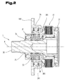
- FIG. 2 is a sectional view of a coupling unit 3 is shown.
- the coupling unit 3 has a coupling shaft 30 which is connected to an output shaft, not shown in the figures the internal combustion engine 2 can be connected.
- the connection of the coupling shaft 30 with the output shaft of the internal combustion engine 2 can be effected by a positive connection.
- the clutch shaft 30 has at its end facing away from the internal combustion engine 2, a cavity into which the in FIG. 3 shown gear coupling means 32 penetrates.
- the coupling shaft 30 carries a coupling means 31, which is designed as a multi-plate clutch, and at least one resilient tensioning means, in particular a spring assembly 33.
- the coupling means 31 is supported by the coupling shaft 30. Furthermore, the coupling means 31 with a in FIG.
- the spring assembly 33 is arranged in the radial direction from a central axis K of the coupling shaft 30 between the coupling shaft 30 and a sleeve-shaped force transmission means 38. Viewed in the axial direction, the spring assembly 33 is disposed between a bearing 37 of the coupling shaft 30 and a projection 380 of the power transmission means 38. In this case, the arrangement of the spring assembly 33 in the coupling unit 3 is seen in the axial direction such that the frictionally acting coupling means 31, in particular a package of disc-shaped friction plates, is biased.
- the amount of bias can be adjusted via the bearing 37 by at least one provided on the clutch shaft 30 shim 34.
- An axial displacement of the at least one adjusting disk 34 in a direction away from the spring assembly 33 is prevented by a securing ring 35.
- the power transmission means 38 is formed axially displaceable along a central axis K of the coupling shaft 30 and has a flange 381 which can be brought into contact with the coupling means 31, in particular with the multi-plate clutch. Due to the bias of the spring assembly 33, and thus the application of force to the force transmitting means 38 via the projection 380, the flange 381 presses against the coupling means 31, so that the coupling means 31 is in a coupled state or constantly urged into the coupling state.
- the coupling unit 3 also has a bush 36 with a protruding portion 360.
- the bushing 36 is farther away from the central axis K than the power transmission means 38 when viewed radially from the central axis K of the clutch shaft 30.
- a bearing 361 Between the bushing 36 and the power transmission means 38 is disposed a bearing 361 such that the bushing 36 relative to the power transmission means 38 can turn.
- the socket 36 is analogous to the power transmission means 38 along the central axis K of the crankshaft 30 axially displaceable.
- the bearing of the coupling shaft 30 by means of two mutually spaced bearings 37.
- the aforementioned bearing 37 are formed as radial bearings.
- the clutch gear 39 is rotatably connected both to the coupling means 31, in particular the multi-plate clutch, as well as to the transmission coupling means 32.
- the gear coupling means 32 is formed coaxially with the coupling shaft 30 and partially protrudes into the cavity of the coupling shaft 32.
- the gear coupling means 32 is formed such that the portion projecting into the cavity of the coupling shaft 30 is not in rotary connection with the coupling shaft 30, thus ensuring in that no rotational movement of the coupling shaft 30 is transmitted directly from this to the transmission coupling means 32 when the coupling means 31 is inactive, ie released or relaxed.
- the gear coupling means 32 has a receiving portion 320, in which a in FIG. 6 shown input shaft 60 of the transmission 6 can penetrate. At the end remote from the gear coupling means 32 end of the coupling shaft 30, a vibration damper 21 is arranged.
- the clutch gear 39 meshes with an intermediate gear 4, which is arranged in the drive unit 1 between the electric machine 11 and the clutch unit 3.
- the intermediate gear 4 is mounted in the housing 10 of the drive unit 1 via bearings 40, in particular radial bearings.
- the electric machine 11 is arranged outside of the preferably lubricating oil-filled housing 10 of the drive unit 1 and has an output shaft 110, which projects partially into the cavity of the housing 10.
- the protruding into the housing 10 section of the output shaft 110 is connected to a gear 111, in particular a form-fitting manner.
- the output shaft 110 and the gear 111 rotate about a center axis A of the output shaft 110.
- the complete electric machine 11 is supported by the housing 10 of the drive unit 1. More specifically, a bearing of the gear 111 and thus the output shaft 110 via spaced radial bearings 113 in the housing 10 of the drive unit 1 takes place. Since the storage of the complete electric machine 11 via the radial bearings 113, the housing 10 is in the sections where the Bearings 113 are arranged, partially reinforced formed, for example, provided with stiffening ribs.
- the output shaft 110 and the clutch shaft 30 are arranged such that their center axes A, K are offset from each other. At this time, the center axis of the output shaft A is parallel to the center axis of the clutch shaft K.
- the output shaft 110 of the electric machine 11 and the output shaft or the rotation axis of the crankshaft of the internal combustion engine 2 are arranged parallel to each other and to align in the same direction or with the same orientation, wherein the drive unit 1diedie two mutually parallel engines by means of Coupling unit 3 with respect to the respectively provided torque as needed coupled or decoupled. That is, the output side of the internal combustion engine 2 and the output side of the electric machine 11 are associated with a unitary side and a common housing wall of the drive unit 1, respectively.
- the drive unit 1 or its housing 10 thus preferably represents a frontal or distal end of this double or parallel unit, whereby the drive unit 1, for example, a downstream gearbox or a subsequent drive train due to a relatively unrestricted space can be easily connected ,
- the housing 10 has a first or front housing section 100 and a second or rear housing section 101, which are connected to one another via screws 102. These housing sections 100, 101 essentially form half shells, which form the housing 10 of the drive unit 1 in the assembled state.
- the rear housing section 101 is connected by screws 114 to a housing 112 of the electric machine 11.
- the bearing of the output shaft 110, the coupling shaft 30 and the intermediate gear 4 takes place such that in each case a bearing on the front Gephaseseab mustard 100 and the respective other, distal bearing on the rear housing portion 101 is arranged.
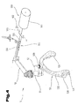
- FIG. 4 there is a perspective view of a switching means 5, by means of which the in FIG. 2 shown coupling unit 3 can be transferred from the coupled state to an uncoupled state.
- the switching means 5 has a lever 50.
- the lever 50 is connected via a shaft 51 with a cam 52.
- Upon rotation of the lever 50 forcibly rotates the shaft 51 and thus the cam 52.
- a rotation of the lever 50 can through an in FIG. 4 schematically indicated actuation means, in particular by an electrically driven or activated actuator 550.
- the switching means 5 has a fork-shaped transmission means 53.
- the fork-shaped transmission means 53 has a shift fork 532 and a cam counterpart 533.
- the shift fork 532 has a substantially U-shape with a base and two legs extending from the base.
- the cam counterpart 533 is arranged on the shift fork 532 such that upon rotation of the lever 50 via the cam 52 on the cam counterpart 533, a restoring force is exerted.
- the cam counterpart 533 is arranged on the basis of the shift fork 532.
- a pivot bearing 530 is respectively arranged, via which the shift fork 532 can rotate.
- a thrust bearing 531 is arranged in each case.
- the switching means 5 can be actuated either manually via muscle power or via the human body weight and also by means of an electrically operable actuator 550.
- the electric actuator 550 may be designed as a servomotor 551, in particular as an electric motor with a spindle gear, whose spindle nut is motion-coupled to the switching means 5:
- the switching means 5 is switchable by means of a lever-shaped cable pull 554, by means of a linkage, by means of a hydraulic cylinder arrangement of master cylinder and slave cylinder or by means of a similar power transmission means 555 applying manual actuation force, whereby the coupling means 31 - Fig. 3 - Can be transferred by purely manual actuation force or by the weight of an operator in the decoupled state.
- the internal combustion engine 2 is secured in the drive disconnected state can be transferred.
- the power transmission means 555 is tensile, but upsetting or shortened executed.
- Such a power transmission means 550 can also be formed by a telescopic tension member 556, which transmits tensile forces and absorbs shear forces or does not transmit to its distal end by telescopic shortening of its length from its first end, as shown in FIG Fig. 4 was indicated schematically.
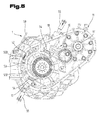
- FIG. 5 shows the switching means 5 in a built-in in the drive unit 1 state. How out FIG. 5 can be seen, there is a fixation of the switching means 5 in at least one cylindrical fixing portion 13 of the housing 10 of the drive unit 1 via bolts 55. More precisely, the bolts 55 are inserted into the respective cylindrical fixing portion 13 and come into contact with the pivot bearing 530 of the shift fork 532 A spring 54 is coupled to the shift fork 532 such that it is ensured that after a return movement of the lever 50 to its undeflected position, the shift fork 532 is also rotated to the undeflected position.
- FIG. 6 a side view of the drive unit 1 is shown, which is coupled to a transmission 6.
- the input shaft 60 of the transmission 6 protrudes into the receiving portion 320 of the gear coupling means 32 and is rotatably connected to the gear coupling means 32.
- the connection can be made positive.
- the drive unit 1 can be operated in three different states. In a first operating state, both the torque of the internal combustion engine 2 and the torque of the electric machine 11 are transmitted to the input shaft 60 of the transmission 6 or to a drive train of a vehicle. In a second operating state, only the torque of the internal combustion engine 2 and in a third operating state only the torque of the electric machine 11 transmitted to the input shaft 60 of the transmission 6.
- the torque of the output shaft of the internal combustion engine 2 is transmitted to the coupling shaft 30 of the coupling unit 3 and thus the coupling means 31. Since the spring pack 33 is in the prestressed state and thus the flange 381 of the power transmission means 38 exerts a force on the coupling means 31, this is in a coupled or coupling state. Thus, the torque of the clutch shaft 30 is transmitted to the clutch gear 39 via the clutch means 31. Since the gear coupling means 32 is non-rotatably connected to the clutch gear 39, the torque of the clutch shaft 30 is finally transmitted to the gear coupling means 32 and to the input shaft 60 of the transmission 6 connected to the gear coupling means 32.
- the torque of the electric machine 11 is transmitted to the intermediate gear 4 via the output shaft 110 or the gear 111 connected to the output shaft 110. Since the intermediate gear 4 meshes with the clutch gear 39, the torque is transmitted from the intermediate gear 4 to the clutch gear 39 and thus to the gear coupling means 32.
- a torque transmission from the output shaft of the internal combustion engine 2 to the input shaft 60 of the transmission 6 is analogous to the first operating state described above.
- the only difference between the two operating states is that in the second operating state of the electric machine 11 no torque is provided. In this state, no electrical energy is consumed or absorbed by the electric machine 11.
- the torque applied by the internal combustion engine 2 to the clutch gear 39 is transmitted to the intermediate gear 4 and thus to the gear 111 of the output shaft 110 of the electric machine 11 in addition to the gear coupling means 32. This ensures that the output shaft 110 of the electric machine 11 rotates upon rotation of the output shaft of the internal combustion engine 2.
- the rotation of the output shaft 110 of the electric machine 11 can be used as a flywheel for the internal combustion engine 2.
- the coupling means in particular the multi-plate clutch, in a transferred uncoupled or decoupled state, so that no torque transmission from the clutch shaft 30 to the clutch gear 39 is more.
- the torque transmission from the output shaft 110 of the electric machine 11 to the gear coupling means 32 takes place in the manner described for the first operating state.
- a decoupling of the clutch shaft 30 from the clutch gear 39 by means of the switching means 5 can be carried out as follows.
- the actuation of the switching means 5 via an actuating means can be done manually or electrically.
- the lever 50 of the switching means 5 is rotated.
- the cam 52 rotates, so that via the cam counterpart 533 a force is exerted on the fork-shaped transmission means 53, which leads to a rotation of the transmission means 53.
- the fork-shaped transmission means 53 rotates about the pivot bearing 533.
- the power transmission means 38 moves axially in a direction away from the coupling means 31. That is, the flange 381 of the power transmission means 38 no longer presses against the coupling means 31.
- the coupling means 38 as a multi-plate clutch is achieved that the blades are no longer pressed against each other, and thus can no longer transmit the torque of the clutch shaft 30 to the clutch gear 39.
- the multi-plate clutch is in an uncoupled or decoupled state.
Landscapes
- Engineering & Computer Science (AREA)
- Mechanical Engineering (AREA)
- Chemical & Material Sciences (AREA)
- Combustion & Propulsion (AREA)
- Transportation (AREA)
- General Engineering & Computer Science (AREA)
- Ocean & Marine Engineering (AREA)
- Hybrid Electric Vehicles (AREA)
- Connection Of Motors, Electrical Generators, Mechanical Devices, And The Like (AREA)
Applications Claiming Priority (1)
| Application Number | Priority Date | Filing Date | Title |
|---|---|---|---|
| ATA1422/2011A AT512710B1 (de) | 2011-09-30 | 2011-09-30 | Antriebseinheit mit einer elektrischen maschine |
Publications (3)
| Publication Number | Publication Date |
|---|---|
| EP2574810A2 true EP2574810A2 (fr) | 2013-04-03 |
| EP2574810A3 EP2574810A3 (fr) | 2014-02-19 |
| EP2574810B1 EP2574810B1 (fr) | 2018-05-02 |
Family
ID=46968058
Family Applications (1)
| Application Number | Title | Priority Date | Filing Date |
|---|---|---|---|
| EP12186609.9A Not-in-force EP2574810B1 (fr) | 2011-09-30 | 2012-09-28 | Unité d'entraînement avec une machine électrique |
Country Status (2)
| Country | Link |
|---|---|
| EP (1) | EP2574810B1 (fr) |
| AT (1) | AT512710B1 (fr) |
Cited By (7)
| Publication number | Priority date | Publication date | Assignee | Title |
|---|---|---|---|---|
| WO2015078543A1 (fr) * | 2013-11-28 | 2015-06-04 | Mtu Friedrichshafen Gmbh | Élément de carter pour entraînement et entraînement |
| DE102016125096A1 (de) * | 2016-12-21 | 2018-06-21 | Schaeffler Technologies AG & Co. KG | Antriebsstrang mit Aktor zur Verbindung einer elektrischen Maschine mit einem Drehteil des Antriebsstranges |
| CN110131390A (zh) * | 2019-05-27 | 2019-08-16 | 杭州萧山江南通用机械有限公司 | 一种油电混合动力输入船用齿轮箱 |
| CN111712648A (zh) * | 2018-02-12 | 2020-09-25 | 舍弗勒技术股份两合公司 | 具有作为离合器载体的扭转减振器的离合器单元、具有离合器单元的混合动力模块 |
| CN114701349A (zh) * | 2022-06-06 | 2022-07-05 | 金翌车业有限公司 | 一种内燃机与插电式混合动力变速器的解耦装置 |
| CN115217857A (zh) * | 2022-06-10 | 2022-10-21 | 浙江吉利控股集团有限公司 | 一种离合器脱开机构和车辆 |
| DE102024117576A1 (de) * | 2024-06-21 | 2025-12-24 | Schaeffler Technologies AG & Co. KG | Hybridmodul |
Families Citing this family (5)
| Publication number | Priority date | Publication date | Assignee | Title |
|---|---|---|---|---|
| DE102013006858B4 (de) | 2013-04-22 | 2023-10-05 | Volkswagen Aktiengesellschaft | Hybridantriebsstrangvorrichtung für ein Kraftfahrzeug |
| DE102014210846B4 (de) * | 2014-06-06 | 2021-08-05 | Zf Friedrichshafen Ag | Reibscheibenkupplung |
| DE102014012397A1 (de) * | 2014-08-20 | 2016-02-25 | Man Truck & Bus Ag | Hybridantriebsanordnung für ein Fahrzeug |
| DE102018216910A1 (de) * | 2018-10-02 | 2020-04-02 | Zf Friedrichshafen Ag | Übersetzungsgetriebe für ein Fahrzeug mit einer Elektromaschine |
| AT526245B1 (de) * | 2022-10-03 | 2024-01-15 | Avl List Gmbh | Maschinenanordnung mit einer Brennkraftmaschine |
Citations (1)
| Publication number | Priority date | Publication date | Assignee | Title |
|---|---|---|---|---|
| WO2006034520A1 (fr) | 2004-09-27 | 2006-04-06 | Magna Steyr Fahrzeugtechnik Ag & Co Kg | Unite d'entrainement pour un vehicule automobile a traction hydride en agencement longitudinal |
Family Cites Families (9)
| Publication number | Priority date | Publication date | Assignee | Title |
|---|---|---|---|---|
| JP3168895B2 (ja) * | 1995-12-06 | 2001-05-21 | トヨタ自動車株式会社 | ハイブリッド駆動装置 |
| DE10209514B4 (de) * | 2001-03-30 | 2016-06-09 | Schaeffler Technologies AG & Co. KG | Antriebsstrang |
| JP3777165B2 (ja) * | 2003-02-25 | 2006-05-24 | 日野自動車株式会社 | ハイブリッド自動車 |
| FR2871110B1 (fr) * | 2004-06-03 | 2006-09-22 | Peugeot Citroen Automobiles Sa | Element de transmission pour une chaine de traction de type hybride parallele |
| DE102007001840A1 (de) * | 2007-01-12 | 2008-07-17 | Voith Patent Gmbh | Hybridantrieb, insbesondere für ein Kraftfahrzeug |
| EP2082955A1 (fr) * | 2008-01-24 | 2009-07-29 | Jegel, Franz Peter, Ing. | Module hybride pour bateaux |
| DE102008061951A1 (de) * | 2008-12-12 | 2010-06-17 | Renk Ag | Schiffsantriebssystem |
| US20110070995A1 (en) * | 2009-09-18 | 2011-03-24 | Aisin Aw Co., Ltd. | Hybrid drive system |
| DE102010046048A1 (de) * | 2010-09-22 | 2012-03-22 | Voith Patent Gmbh | Antriebsvorrichtung |
-
2011
- 2011-09-30 AT ATA1422/2011A patent/AT512710B1/de not_active IP Right Cessation
-
2012
- 2012-09-28 EP EP12186609.9A patent/EP2574810B1/fr not_active Not-in-force
Patent Citations (1)
| Publication number | Priority date | Publication date | Assignee | Title |
|---|---|---|---|---|
| WO2006034520A1 (fr) | 2004-09-27 | 2006-04-06 | Magna Steyr Fahrzeugtechnik Ag & Co Kg | Unite d'entrainement pour un vehicule automobile a traction hydride en agencement longitudinal |
Cited By (10)
| Publication number | Priority date | Publication date | Assignee | Title |
|---|---|---|---|---|
| WO2015078543A1 (fr) * | 2013-11-28 | 2015-06-04 | Mtu Friedrichshafen Gmbh | Élément de carter pour entraînement et entraînement |
| DE102016125096A1 (de) * | 2016-12-21 | 2018-06-21 | Schaeffler Technologies AG & Co. KG | Antriebsstrang mit Aktor zur Verbindung einer elektrischen Maschine mit einem Drehteil des Antriebsstranges |
| DE102016125096B4 (de) * | 2016-12-21 | 2019-09-19 | Schaeffler Technologies AG & Co. KG | Antriebsstrang mit Aktor zur Verbindung einer elektrischen Maschine mit einem Drehteil des Antriebsstranges |
| CN111712648A (zh) * | 2018-02-12 | 2020-09-25 | 舍弗勒技术股份两合公司 | 具有作为离合器载体的扭转减振器的离合器单元、具有离合器单元的混合动力模块 |
| CN110131390A (zh) * | 2019-05-27 | 2019-08-16 | 杭州萧山江南通用机械有限公司 | 一种油电混合动力输入船用齿轮箱 |
| CN110131390B (zh) * | 2019-05-27 | 2024-01-26 | 杭州萧山江南通用机械有限公司 | 一种油电混合动力输入船用齿轮箱 |
| CN114701349A (zh) * | 2022-06-06 | 2022-07-05 | 金翌车业有限公司 | 一种内燃机与插电式混合动力变速器的解耦装置 |
| CN114701349B (zh) * | 2022-06-06 | 2022-08-19 | 金翌车业有限公司 | 一种内燃机与插电式混合动力变速器的解耦装置 |
| CN115217857A (zh) * | 2022-06-10 | 2022-10-21 | 浙江吉利控股集团有限公司 | 一种离合器脱开机构和车辆 |
| DE102024117576A1 (de) * | 2024-06-21 | 2025-12-24 | Schaeffler Technologies AG & Co. KG | Hybridmodul |
Also Published As
| Publication number | Publication date |
|---|---|
| AT512710A1 (de) | 2013-10-15 |
| AT512710B1 (de) | 2014-06-15 |
| EP2574810A3 (fr) | 2014-02-19 |
| EP2574810B1 (fr) | 2018-05-02 |
Similar Documents
| Publication | Publication Date | Title |
|---|---|---|
| EP2574810B1 (fr) | Unité d'entraînement avec une machine électrique | |
| DE102008013054B4 (de) | Stellmechanismus zum Ein- und Ausrücken einer Trennkupplung mit drehbarem Kurvensegment | |
| DE102010061597B4 (de) | Motorgetriebene Säulenvorrichtung eines unteren Typs | |
| WO2015070850A1 (fr) | Support de couple d'un actionneur monté sur un carter d'embrayage/d'engrenages | |
| DE102005012380B4 (de) | Nicht abgedichtete Parkstellgliedführung für Hybridgetriebe | |
| WO2020114548A1 (fr) | Actionneur de frein de stationnement à intégrer dans une transmission de véhicule | |
| DE102016122378A1 (de) | Lenksystem | |
| DE102013113371B4 (de) | System zum Betätigen eines Trockendoppelkupplungsgetriebes unter Verwendung eines Elektromotors mit kraftunterstütztem Hebel | |
| CH648102A5 (de) | Abzweiggetriebe fuer einen schiffsantrieb. | |
| EP2704929B1 (fr) | Mécanisme d'arrêt | |
| DE10248485A1 (de) | Verfahren zur Herstellung einer Antriebshohlwelle zum Einsatz bei einem Fahrzeugantriebsstrangsystem | |
| DE102008021196A1 (de) | Startereinrichtung für ein Motorgerät mit einer verbesserten Dämpfung | |
| DE102017218638A1 (de) | Betätigungsanordnung für eine Parksperre für ein Kraftfahrzeug | |
| DE102005012382B4 (de) | Elektromechanisches Hybridgetriebe mit gesicherter Nabe für eine Parksperrlast | |
| EP2527237A1 (fr) | Bras oscillant doté d'une transmission par chaîne à deux niveaux | |
| DE102005012381B4 (de) | Abdeckung für einen Zugang zu einem Parksystem eines elektromechanischen Hybridgetriebes und Verfahren dafür | |
| DE102016119367A1 (de) | Lenksystem | |
| DE1752294A1 (de) | Tragbares kraftgetriebenes Werkzeug | |
| DE102017124131A1 (de) | Betätigungsvorrichtung mit zwei Kugelsegmenten mit unterschiedlichem Durchmesser und Schalteinheit | |
| WO2012094686A2 (fr) | Système d'entraînement à moteur et à pédales combiné pour un véhicule, en particulier un véhicule marin | |
| DE102017107887A1 (de) | Betätigungsvorrichtung für ein Kraftfahrzeuggetriebe und Schalteinheit | |
| DE112007002890T5 (de) | Lenkvorrichtung mit einer Kugelumlaufspindel | |
| DE102016103197A1 (de) | Riemengetriebe und lenksystem | |
| EP2527236B1 (fr) | Ensemble de transmission à changement de vitesse | |
| EP1508715A2 (fr) | Dispositif d'actionnement d'un embrayage double |
Legal Events
| Date | Code | Title | Description |
|---|---|---|---|
| PUAI | Public reference made under article 153(3) epc to a published international application that has entered the european phase |
Free format text: ORIGINAL CODE: 0009012 |
|
| AK | Designated contracting states |
Kind code of ref document: A2 Designated state(s): AL AT BE BG CH CY CZ DE DK EE ES FI FR GB GR HR HU IE IS IT LI LT LU LV MC MK MT NL NO PL PT RO RS SE SI SK SM TR |
|
| AX | Request for extension of the european patent |
Extension state: BA ME |
|
| PUAL | Search report despatched |
Free format text: ORIGINAL CODE: 0009013 |
|
| AK | Designated contracting states |
Kind code of ref document: A3 Designated state(s): AL AT BE BG CH CY CZ DE DK EE ES FI FR GB GR HR HU IE IS IT LI LT LU LV MC MK MT NL NO PL PT RO RS SE SI SK SM TR |
|
| AX | Request for extension of the european patent |
Extension state: BA ME |
|
| RIC1 | Information provided on ipc code assigned before grant |
Ipc: B60K 6/40 20071001ALI20140116BHEP Ipc: F16D 23/12 20060101AFI20140116BHEP Ipc: F16D 13/56 20060101ALI20140116BHEP Ipc: B60K 6/48 20071001ALI20140116BHEP Ipc: B60K 6/387 20071001ALI20140116BHEP |
|
| 17P | Request for examination filed |
Effective date: 20140813 |
|
| RBV | Designated contracting states (corrected) |
Designated state(s): AL AT BE BG CH CY CZ DE DK EE ES FI FR GB GR HR HU IE IS IT LI LT LU LV MC MK MT NL NO PL PT RO RS SE SI SK SM TR |
|
| GRAP | Despatch of communication of intention to grant a patent |
Free format text: ORIGINAL CODE: EPIDOSNIGR1 |
|
| INTG | Intention to grant announced |
Effective date: 20171211 |
|
| GRAS | Grant fee paid |
Free format text: ORIGINAL CODE: EPIDOSNIGR3 |
|
| GRAA | (expected) grant |
Free format text: ORIGINAL CODE: 0009210 |
|
| RAP1 | Party data changed (applicant data changed or rights of an application transferred) |
Owner name: STEYR MOTORS GMBH |
|
| RIN1 | Information on inventor provided before grant (corrected) |
Inventor name: MANDORFER, RUDOLF Inventor name: RESCH, BERNHARD Inventor name: ASCHABER, MICHAEL |
|
| AK | Designated contracting states |
Kind code of ref document: B1 Designated state(s): AL AT BE BG CH CY CZ DE DK EE ES FI FR GB GR HR HU IE IS IT LI LT LU LV MC MK MT NL NO PL PT RO RS SE SI SK SM TR |
|
| REG | Reference to a national code |
Ref country code: GB Ref legal event code: FG4D Free format text: NOT ENGLISH |
|
| REG | Reference to a national code |
Ref country code: CH Ref legal event code: EP Ref country code: AT Ref legal event code: REF Ref document number: 995594 Country of ref document: AT Kind code of ref document: T Effective date: 20180515 |
|
| REG | Reference to a national code |
Ref country code: DE Ref legal event code: R096 Ref document number: 502012012623 Country of ref document: DE Ref country code: IE Ref legal event code: FG4D Free format text: LANGUAGE OF EP DOCUMENT: GERMAN |
|
| REG | Reference to a national code |
Ref country code: FR Ref legal event code: PLFP Year of fee payment: 7 |
|
| REG | Reference to a national code |
Ref country code: NL Ref legal event code: MP Effective date: 20180502 |
|
| REG | Reference to a national code |
Ref country code: LT Ref legal event code: MG4D |
|
| PG25 | Lapsed in a contracting state [announced via postgrant information from national office to epo] |
Ref country code: FI Free format text: LAPSE BECAUSE OF FAILURE TO SUBMIT A TRANSLATION OF THE DESCRIPTION OR TO PAY THE FEE WITHIN THE PRESCRIBED TIME-LIMIT Effective date: 20180502 Ref country code: BG Free format text: LAPSE BECAUSE OF FAILURE TO SUBMIT A TRANSLATION OF THE DESCRIPTION OR TO PAY THE FEE WITHIN THE PRESCRIBED TIME-LIMIT Effective date: 20180802 Ref country code: LT Free format text: LAPSE BECAUSE OF FAILURE TO SUBMIT A TRANSLATION OF THE DESCRIPTION OR TO PAY THE FEE WITHIN THE PRESCRIBED TIME-LIMIT Effective date: 20180502 Ref country code: ES Free format text: LAPSE BECAUSE OF FAILURE TO SUBMIT A TRANSLATION OF THE DESCRIPTION OR TO PAY THE FEE WITHIN THE PRESCRIBED TIME-LIMIT Effective date: 20180502 Ref country code: SE Free format text: LAPSE BECAUSE OF FAILURE TO SUBMIT A TRANSLATION OF THE DESCRIPTION OR TO PAY THE FEE WITHIN THE PRESCRIBED TIME-LIMIT Effective date: 20180502 Ref country code: NO Free format text: LAPSE BECAUSE OF FAILURE TO SUBMIT A TRANSLATION OF THE DESCRIPTION OR TO PAY THE FEE WITHIN THE PRESCRIBED TIME-LIMIT Effective date: 20180802 |
|
| PGFP | Annual fee paid to national office [announced via postgrant information from national office to epo] |
Ref country code: FR Payment date: 20180723 Year of fee payment: 7 Ref country code: DE Payment date: 20180723 Year of fee payment: 7 |
|
| PG25 | Lapsed in a contracting state [announced via postgrant information from national office to epo] |
Ref country code: LV Free format text: LAPSE BECAUSE OF FAILURE TO SUBMIT A TRANSLATION OF THE DESCRIPTION OR TO PAY THE FEE WITHIN THE PRESCRIBED TIME-LIMIT Effective date: 20180502 Ref country code: RS Free format text: LAPSE BECAUSE OF FAILURE TO SUBMIT A TRANSLATION OF THE DESCRIPTION OR TO PAY THE FEE WITHIN THE PRESCRIBED TIME-LIMIT Effective date: 20180502 Ref country code: HR Free format text: LAPSE BECAUSE OF FAILURE TO SUBMIT A TRANSLATION OF THE DESCRIPTION OR TO PAY THE FEE WITHIN THE PRESCRIBED TIME-LIMIT Effective date: 20180502 Ref country code: GR Free format text: LAPSE BECAUSE OF FAILURE TO SUBMIT A TRANSLATION OF THE DESCRIPTION OR TO PAY THE FEE WITHIN THE PRESCRIBED TIME-LIMIT Effective date: 20180803 Ref country code: NL Free format text: LAPSE BECAUSE OF FAILURE TO SUBMIT A TRANSLATION OF THE DESCRIPTION OR TO PAY THE FEE WITHIN THE PRESCRIBED TIME-LIMIT Effective date: 20180502 |
|
| PGFP | Annual fee paid to national office [announced via postgrant information from national office to epo] |
Ref country code: AT Payment date: 20180724 Year of fee payment: 7 |
|
| PG25 | Lapsed in a contracting state [announced via postgrant information from national office to epo] |
Ref country code: PT Free format text: LAPSE BECAUSE OF FAILURE TO SUBMIT A TRANSLATION OF THE DESCRIPTION OR TO PAY THE FEE WITHIN THE PRESCRIBED TIME-LIMIT Effective date: 20180903 |
|
| PG25 | Lapsed in a contracting state [announced via postgrant information from national office to epo] |
Ref country code: PL Free format text: LAPSE BECAUSE OF FAILURE TO SUBMIT A TRANSLATION OF THE DESCRIPTION OR TO PAY THE FEE WITHIN THE PRESCRIBED TIME-LIMIT Effective date: 20180502 Ref country code: EE Free format text: LAPSE BECAUSE OF FAILURE TO SUBMIT A TRANSLATION OF THE DESCRIPTION OR TO PAY THE FEE WITHIN THE PRESCRIBED TIME-LIMIT Effective date: 20180502 Ref country code: SK Free format text: LAPSE BECAUSE OF FAILURE TO SUBMIT A TRANSLATION OF THE DESCRIPTION OR TO PAY THE FEE WITHIN THE PRESCRIBED TIME-LIMIT Effective date: 20180502 Ref country code: CZ Free format text: LAPSE BECAUSE OF FAILURE TO SUBMIT A TRANSLATION OF THE DESCRIPTION OR TO PAY THE FEE WITHIN THE PRESCRIBED TIME-LIMIT Effective date: 20180502 Ref country code: RO Free format text: LAPSE BECAUSE OF FAILURE TO SUBMIT A TRANSLATION OF THE DESCRIPTION OR TO PAY THE FEE WITHIN THE PRESCRIBED TIME-LIMIT Effective date: 20180502 Ref country code: DK Free format text: LAPSE BECAUSE OF FAILURE TO SUBMIT A TRANSLATION OF THE DESCRIPTION OR TO PAY THE FEE WITHIN THE PRESCRIBED TIME-LIMIT Effective date: 20180502 |
|
| REG | Reference to a national code |
Ref country code: CH Ref legal event code: PK Free format text: BERICHTIGUNGEN |
|
| REG | Reference to a national code |
Ref country code: DE Ref legal event code: R097 Ref document number: 502012012623 Country of ref document: DE |
|
| RIC2 | Information provided on ipc code assigned after grant |
Ipc: F16D 23/12 20060101AFI20140116BHEP Ipc: B60K 6/48 20071001ALI20140116BHEP Ipc: B60K 6/387 20071001ALI20140116BHEP Ipc: F16D 13/56 20060101ALI20140116BHEP Ipc: B60K 6/40 20071001ALI20140116BHEP |
|
| PG25 | Lapsed in a contracting state [announced via postgrant information from national office to epo] |
Ref country code: SM Free format text: LAPSE BECAUSE OF FAILURE TO SUBMIT A TRANSLATION OF THE DESCRIPTION OR TO PAY THE FEE WITHIN THE PRESCRIBED TIME-LIMIT Effective date: 20180502 Ref country code: IT Free format text: LAPSE BECAUSE OF FAILURE TO SUBMIT A TRANSLATION OF THE DESCRIPTION OR TO PAY THE FEE WITHIN THE PRESCRIBED TIME-LIMIT Effective date: 20180502 |
|
| PLBE | No opposition filed within time limit |
Free format text: ORIGINAL CODE: 0009261 |
|
| STAA | Information on the status of an ep patent application or granted ep patent |
Free format text: STATUS: NO OPPOSITION FILED WITHIN TIME LIMIT |
|
| 26N | No opposition filed |
Effective date: 20190205 |
|
| PG25 | Lapsed in a contracting state [announced via postgrant information from national office to epo] |
Ref country code: MC Free format text: LAPSE BECAUSE OF FAILURE TO SUBMIT A TRANSLATION OF THE DESCRIPTION OR TO PAY THE FEE WITHIN THE PRESCRIBED TIME-LIMIT Effective date: 20180502 |
|
| REG | Reference to a national code |
Ref country code: CH Ref legal event code: PL |
|
| GBPC | Gb: european patent ceased through non-payment of renewal fee |
Effective date: 20180928 |
|
| PG25 | Lapsed in a contracting state [announced via postgrant information from national office to epo] |
Ref country code: SI Free format text: LAPSE BECAUSE OF FAILURE TO SUBMIT A TRANSLATION OF THE DESCRIPTION OR TO PAY THE FEE WITHIN THE PRESCRIBED TIME-LIMIT Effective date: 20180502 |
|
| REG | Reference to a national code |
Ref country code: BE Ref legal event code: MM Effective date: 20180930 |
|
| REG | Reference to a national code |
Ref country code: IE Ref legal event code: MM4A |
|
| PG25 | Lapsed in a contracting state [announced via postgrant information from national office to epo] |
Ref country code: LU Free format text: LAPSE BECAUSE OF NON-PAYMENT OF DUE FEES Effective date: 20180928 |
|
| PG25 | Lapsed in a contracting state [announced via postgrant information from national office to epo] |
Ref country code: IE Free format text: LAPSE BECAUSE OF NON-PAYMENT OF DUE FEES Effective date: 20180928 |
|
| PG25 | Lapsed in a contracting state [announced via postgrant information from national office to epo] |
Ref country code: LI Free format text: LAPSE BECAUSE OF NON-PAYMENT OF DUE FEES Effective date: 20180930 Ref country code: CH Free format text: LAPSE BECAUSE OF NON-PAYMENT OF DUE FEES Effective date: 20180930 Ref country code: BE Free format text: LAPSE BECAUSE OF NON-PAYMENT OF DUE FEES Effective date: 20180930 |
|
| PG25 | Lapsed in a contracting state [announced via postgrant information from national office to epo] |
Ref country code: GB Free format text: LAPSE BECAUSE OF NON-PAYMENT OF DUE FEES Effective date: 20180928 |
|
| PG25 | Lapsed in a contracting state [announced via postgrant information from national office to epo] |
Ref country code: AL Free format text: LAPSE BECAUSE OF FAILURE TO SUBMIT A TRANSLATION OF THE DESCRIPTION OR TO PAY THE FEE WITHIN THE PRESCRIBED TIME-LIMIT Effective date: 20180502 |
|
| PG25 | Lapsed in a contracting state [announced via postgrant information from national office to epo] |
Ref country code: MT Free format text: LAPSE BECAUSE OF FAILURE TO SUBMIT A TRANSLATION OF THE DESCRIPTION OR TO PAY THE FEE WITHIN THE PRESCRIBED TIME-LIMIT Effective date: 20180502 |
|
| PG25 | Lapsed in a contracting state [announced via postgrant information from national office to epo] |
Ref country code: TR Free format text: LAPSE BECAUSE OF FAILURE TO SUBMIT A TRANSLATION OF THE DESCRIPTION OR TO PAY THE FEE WITHIN THE PRESCRIBED TIME-LIMIT Effective date: 20180502 |
|
| REG | Reference to a national code |
Ref country code: DE Ref legal event code: R119 Ref document number: 502012012623 Country of ref document: DE |
|
| PG25 | Lapsed in a contracting state [announced via postgrant information from national office to epo] |
Ref country code: HU Free format text: LAPSE BECAUSE OF FAILURE TO SUBMIT A TRANSLATION OF THE DESCRIPTION OR TO PAY THE FEE WITHIN THE PRESCRIBED TIME-LIMIT; INVALID AB INITIO Effective date: 20120928 |
|
| PG25 | Lapsed in a contracting state [announced via postgrant information from national office to epo] |
Ref country code: MK Free format text: LAPSE BECAUSE OF NON-PAYMENT OF DUE FEES Effective date: 20180502 Ref country code: CY Free format text: LAPSE BECAUSE OF FAILURE TO SUBMIT A TRANSLATION OF THE DESCRIPTION OR TO PAY THE FEE WITHIN THE PRESCRIBED TIME-LIMIT Effective date: 20180502 |
|
| PG25 | Lapsed in a contracting state [announced via postgrant information from national office to epo] |
Ref country code: DE Free format text: LAPSE BECAUSE OF NON-PAYMENT OF DUE FEES Effective date: 20200401 Ref country code: IS Free format text: LAPSE BECAUSE OF FAILURE TO SUBMIT A TRANSLATION OF THE DESCRIPTION OR TO PAY THE FEE WITHIN THE PRESCRIBED TIME-LIMIT Effective date: 20180902 |
|
| REG | Reference to a national code |
Ref country code: AT Ref legal event code: MM01 Ref document number: 995594 Country of ref document: AT Kind code of ref document: T Effective date: 20190928 |
|
| PG25 | Lapsed in a contracting state [announced via postgrant information from national office to epo] |
Ref country code: FR Free format text: LAPSE BECAUSE OF NON-PAYMENT OF DUE FEES Effective date: 20190930 |
|
| PG25 | Lapsed in a contracting state [announced via postgrant information from national office to epo] |
Ref country code: AT Free format text: LAPSE BECAUSE OF NON-PAYMENT OF DUE FEES Effective date: 20190928 |