EP2574885A1 - Verfahren und Vorrichtung zum Bestimmen der Masse von Partikeln in einem Fluid - Google Patents
Verfahren und Vorrichtung zum Bestimmen der Masse von Partikeln in einem Fluid Download PDFInfo
- Publication number
- EP2574885A1 EP2574885A1 EP12186095A EP12186095A EP2574885A1 EP 2574885 A1 EP2574885 A1 EP 2574885A1 EP 12186095 A EP12186095 A EP 12186095A EP 12186095 A EP12186095 A EP 12186095A EP 2574885 A1 EP2574885 A1 EP 2574885A1
- Authority
- EP
- European Patent Office
- Prior art keywords
- oscillator
- trapping
- fluidic
- detection device
- fluidic network
- Prior art date
- Legal status (The legal status is an assumption and is not a legal conclusion. Google has not performed a legal analysis and makes no representation as to the accuracy of the status listed.)
- Granted
Links
- 239000002245 particle Substances 0.000 title claims abstract description 77
- 239000012530 fluid Substances 0.000 title claims abstract description 37
- 238000001514 detection method Methods 0.000 title claims description 50
- 238000000034 method Methods 0.000 title claims description 6
- 230000005284 excitation Effects 0.000 claims abstract description 14
- 238000004891 communication Methods 0.000 claims abstract description 11
- 238000000105 evaporative light scattering detection Methods 0.000 claims abstract description 11
- 239000007788 liquid Substances 0.000 claims description 18
- 210000001015 abdomen Anatomy 0.000 claims description 10
- 230000003287 optical effect Effects 0.000 claims description 7
- 239000012528 membrane Substances 0.000 claims description 5
- 238000002493 microarray Methods 0.000 claims description 4
- 239000002070 nanowire Substances 0.000 claims description 3
- 241000894007 species Species 0.000 description 9
- 230000007246 mechanism Effects 0.000 description 6
- 230000004044 response Effects 0.000 description 6
- 238000011144 upstream manufacturing Methods 0.000 description 6
- 230000035945 sensitivity Effects 0.000 description 5
- 239000000126 substance Substances 0.000 description 5
- 230000008878 coupling Effects 0.000 description 4
- 238000010168 coupling process Methods 0.000 description 4
- 238000005859 coupling reaction Methods 0.000 description 4
- 238000004519 manufacturing process Methods 0.000 description 4
- 239000000758 substrate Substances 0.000 description 4
- 210000003462 vein Anatomy 0.000 description 4
- 241000894006 Bacteria Species 0.000 description 3
- 241000700605 Viruses Species 0.000 description 3
- 239000011324 bead Substances 0.000 description 3
- 238000005452 bending Methods 0.000 description 2
- 230000008901 benefit Effects 0.000 description 2
- 239000013626 chemical specie Substances 0.000 description 2
- 238000012937 correction Methods 0.000 description 2
- 238000007306 functionalization reaction Methods 0.000 description 2
- 239000011521 glass Substances 0.000 description 2
- 238000013507 mapping Methods 0.000 description 2
- 238000012545 processing Methods 0.000 description 2
- 108090000623 proteins and genes Proteins 0.000 description 2
- 102000004169 proteins and genes Human genes 0.000 description 2
- 108020004414 DNA Proteins 0.000 description 1
- 239000003298 DNA probe Substances 0.000 description 1
- 101100460147 Sarcophaga bullata NEMS gene Proteins 0.000 description 1
- 241001080024 Telles Species 0.000 description 1
- 238000004458 analytical method Methods 0.000 description 1
- 239000000427 antigen Substances 0.000 description 1
- 102000036639 antigens Human genes 0.000 description 1
- 108091007433 antigens Proteins 0.000 description 1
- 230000000903 blocking effect Effects 0.000 description 1
- 238000012512 characterization method Methods 0.000 description 1
- 238000006243 chemical reaction Methods 0.000 description 1
- 238000004163 cytometry Methods 0.000 description 1
- 238000013016 damping Methods 0.000 description 1
- 230000007423 decrease Effects 0.000 description 1
- 230000008021 deposition Effects 0.000 description 1
- 238000009826 distribution Methods 0.000 description 1
- 230000000694 effects Effects 0.000 description 1
- 230000001747 exhibiting effect Effects 0.000 description 1
- 230000002349 favourable effect Effects 0.000 description 1
- 238000001914 filtration Methods 0.000 description 1
- 239000012634 fragment Substances 0.000 description 1
- 238000009396 hybridization Methods 0.000 description 1
- 239000000463 material Substances 0.000 description 1
- 238000005259 measurement Methods 0.000 description 1
- 239000002184 metal Substances 0.000 description 1
- 239000011325 microbead Substances 0.000 description 1
- 239000011859 microparticle Substances 0.000 description 1
- 238000012986 modification Methods 0.000 description 1
- 230000004048 modification Effects 0.000 description 1
- 239000002090 nanochannel Substances 0.000 description 1
- 239000002105 nanoparticle Substances 0.000 description 1
- 230000003534 oscillatory effect Effects 0.000 description 1
- 244000052769 pathogen Species 0.000 description 1
- 108090000765 processed proteins & peptides Proteins 0.000 description 1
- 238000013139 quantization Methods 0.000 description 1
- 230000007261 regionalization Effects 0.000 description 1
- 238000005204 segregation Methods 0.000 description 1
- 210000002966 serum Anatomy 0.000 description 1
- 238000004513 sizing Methods 0.000 description 1
- 238000011895 specific detection Methods 0.000 description 1
Images


Classifications
-
- G—PHYSICS
- G01—MEASURING; TESTING
- G01G—WEIGHING
- G01G3/00—Weighing apparatus characterised by the use of elastically-deformable members, e.g. spring balances
- G01G3/12—Weighing apparatus characterised by the use of elastically-deformable members, e.g. spring balances wherein the weighing element is in the form of a solid body stressed by pressure or tension during weighing
- G01G3/16—Weighing apparatus characterised by the use of elastically-deformable members, e.g. spring balances wherein the weighing element is in the form of a solid body stressed by pressure or tension during weighing measuring variations of frequency of oscillations of the body
-
- G—PHYSICS
- G01—MEASURING; TESTING
- G01N—INVESTIGATING OR ANALYSING MATERIALS BY DETERMINING THEIR CHEMICAL OR PHYSICAL PROPERTIES
- G01N15/00—Investigating characteristics of particles; Investigating permeability, pore-volume or surface-area of porous materials
- G01N15/02—Investigating particle size or size distribution
-
- G—PHYSICS
- G01—MEASURING; TESTING
- G01N—INVESTIGATING OR ANALYSING MATERIALS BY DETERMINING THEIR CHEMICAL OR PHYSICAL PROPERTIES
- G01N15/00—Investigating characteristics of particles; Investigating permeability, pore-volume or surface-area of porous materials
- G01N15/10—Investigating individual particles
- G01N15/14—Optical investigation techniques, e.g. flow cytometry
- G01N15/1484—Optical investigation techniques, e.g. flow cytometry microstructural devices
-
- G—PHYSICS
- G01—MEASURING; TESTING
- G01N—INVESTIGATING OR ANALYSING MATERIALS BY DETERMINING THEIR CHEMICAL OR PHYSICAL PROPERTIES
- G01N5/00—Analysing materials by weighing, e.g. weighing small particles separated from a gas or liquid
- G01N5/02—Analysing materials by weighing, e.g. weighing small particles separated from a gas or liquid by absorbing or adsorbing components of a material and determining change of weight of the adsorbent, e.g. determining moisture content
-
- G—PHYSICS
- G01—MEASURING; TESTING
- G01N—INVESTIGATING OR ANALYSING MATERIALS BY DETERMINING THEIR CHEMICAL OR PHYSICAL PROPERTIES
- G01N15/00—Investigating characteristics of particles; Investigating permeability, pore-volume or surface-area of porous materials
- G01N15/10—Investigating individual particles
- G01N2015/1021—Measuring mass of individual particles
Definitions
- the present invention relates to the field of mass or gravimetric detection from liquid samples using NEMS / MEMS resonant structures (Nano / Micro Electro Mechanical System).
- the mass detection technique is based on the detection and quantization of the resonance frequency shifts of an electromechanical oscillator when a particle is deposited on its surface.
- particle means a ball (pre-functionalized or not) of micrometric or nanometric size, but also a chemical or biological object of the protein, peptide, DNA fragment, bacterium, virus, or other cells, etc.
- the oscillator is in the form of a cantilever beam in which a fluidic vein is provided.
- the oscillator is vibrated by electrostatic coupling, while the fluid to be analyzed flows in the fluidic vein controlled by a pressure differential.
- This device makes it possible to detect biological species in a liquid medium while maintaining the oscillatory movement in a dry environment (air or moderate vacuum).
- Two mechanisms are provided for temporarily holding particles at the free end of the beam.
- a first mechanism adapted to out-of-plane vibrating structures concerns the adjustment of the centrifugal force induced by the vibratory motion of the oscillator, having the flow controlled by a pressure differential in the fluidic vein.
- a second mechanism for temporarily holding particles relates to the rapid alternation of the direction of fluid flow.
- oscillators comprising a fluidic vein whose inner wall is functionalized to allow to hang biological or chemical species determined according to their affinity. This assumes a prior and inconvenient stage of chemical functionalization throughout the fluidic network. In addition, the same device can only be dedicated to the capture of a single biological or chemical species.
- This device comprises a planar electromechanical oscillator comprising a fluidic channel in communication with a through cavity formed in the oscillator and actuating means of the oscillator by electrostatic coupling. Particle trapping is achieved chemically by functionalizing the inner wall of the cavity within the oscillator or electrically based on a dielectrophoretic effect in a quadrupole configuration of the electrodes. This device allows the trapping of the particles only according to their biological nature.
- the object of the present invention is to overcome the aforementioned drawbacks by providing a device for mass detection of particles in a fluid medium of optimal sensitivity while allowing a simple, effective, and more distinctive trapping of the particles.
- the subject of the invention is a device for mass detection of particles in a liquid medium, comprising an electromechanical oscillator, excitation means arranged to vibrate said oscillator, a fluidic supply circuit, and a fluidic network integrated in said oscillator.
- said fluidic network being in fluid communication with the fluidic supply circuit, the fluidic network comprising at least one trapping site configured to trap a particle of interest depending on the size of said particle of interest.
- the particles of interest can be detected selectively according to their size.
- said trapping site is located at a vibration belly of the electromechanical oscillator.
- the trapping sites are placed at the most favorable places to optimize the sensitivity of the detection. Indeed, the position of the trapped particle at a location having a maximum amplitude of vibration increases the offset of the resonant frequency and therefore optimizes the detection of the particle and increases the sensitivity of the detection device.
- said trapping site is formed in a fluidic trapping branch mounted in parallel with a bypass fluid branch, said trapping branch having, in the case where the trapping site is free, a lower fluid resistance than that of said branch of bypass.
- the fluidic network comprises a fluidic trapping branch forming said trapping site, and a bypass fluid branch which is mounted in shunt with respect to said trapping fluidic branch, said trapping fluidic branch comprising a housing extended by a restriction.
- said trapping and bypassing fluidic branches being dimensioned so that when said housing is free, said trapping branch has a lower fluidic resistance than said bypassing branch causing a first particle of interest to pass through the branch trapping to be done trapping in said housing, and when said housing is occupied, said trapping branch has a higher fluid resistance than said bypass branch causing a next particle of interest to pass through the branch bypass.
- the present invention enables efficient coupling between locations corresponding to optimal mechanical mass-sensing responses of particles and passive fluid trapping based on particle size selection.
- the fluidic network comprises a plurality of trapping sites located at the levels of different vibrational bellies of said oscillator.
- the fluidic network is a microarray or a fluidic nanoretwork.
- the trapping sites are arranged in series at the terminals of the supply circuit.
- the trapping sites are arranged in parallel across the power supply circuit.
- said oscillator is hollow recessed plate type having a shape taken from a disk, a ring, and a polygon.
- said oscillator is a resonator of cantilever beam, bi-embedded beam, nanowire, or membrane type.
- said oscillator is square in shape and has a width and a thickness such that the ratio of the width to the thickness is greater than 10, and for example between 10 and 30.
- the device comprises excitation means and detection means which are selected from the following means: capacitive, piezoelectric, piezo-metallic, electromagnetic, piezoresistive, thermal, thermoelastic, and optical.
- the supply circuit comprises first and second supply channels which are separated from each other by the fluidic network, said fluidic network being in communication with the first supply channel and the first supply channel. secondly with the second supply channel so that the flow rate in the fluidic network is controllable by adjusting flow rates in the first and second supply channels.
- the detection system comprises a set of electromechanical oscillators of different scales, each of the oscillators integrating a fluidic network of a corresponding scale, the different fluidic networks being in communication with the first and second supply channels.
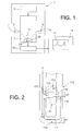
- the Fig. 1 illustrates very schematically a device for mass detection of particles in a liquid medium, according to the invention.
- the detection device 3 comprises a supply fluid circuit 5, an electromechanical oscillator 7 (or resonator), excitation means 9 arranged to vibrate the oscillator 7, and a fluidic network 11 integrated in the oscillator 7. and supplied with liquid (solution of interest) F by the supply fluid circuit 5.
- the electromechanical oscillator 7 may be in the form of a beam, a wire, a membrane or a plate supported by support means (see FIG. Fig. 3 ).
- the fluidic network 11 is preferably integrated in the oscillator 7 so that the liquid (or fluid) F analyzed by the detection device 3 is sealed from the environment in which the oscillator 7 is actuated.
- the fluidic network 11 is a microarray or a fluidic nanoretwork that may consist of substantially parallelepiped-shaped channels etched within the oscillator 7.
- the excitation means 9 advantageously comprise electrodes arranged opposite the oscillator 7. These electrodes are implemented and arranged relative to the oscillator 7 so that the latter can vibrate according to a specific vibration mode.
- detection means 13 for detecting the vibration of oscillator 7 may also comprise electrodes arranged opposite oscillator 7. In this case, detection means 13 are advantageously integrated with detection device 3. detection means 13 are configured to detect variations in the vibration frequency or resonant frequency of the oscillator 7, knowing that any variation in frequency is indicative of a mass variation of the oscillator 7, in particular, following a deposition of particles in the latter.
- the detection means 13 may be connected to a processing device 15 of the computer type comprising display means 17 for analyzing the evolution of the resonant frequency and thus proceeding to the detection of particles.
- the particles may be functionalized beads, for example metal balls whose surface is functionalized, so as to form a collection surface (or capture surface) of a chemical or biological species, called target species.
- a chemical or biological species called target species.
- an oscillator 7 of the same type it is possible to modulate the type of ball introduced, and in particular according to the functionalization of its external surface, so as to collect a species given chemical or biological
- the mass of the oscillator 7 increases, causing a variation in the resonance frequency, the determination of which makes it possible to quantify the mass of the target species collected. This makes it possible to estimate the quantity or the concentration of the target species in the liquid circulating in the fluidic network 11.
- the particles can also be biological species of cell, bacteria or virus type.
- the evolution of the mass of the oscillator 7 then makes it possible to determine the behavior of the species in the latter. For example, one can introduce a cell and stress it (by subjecting it to a particular fluid) and check if it lives (its mass remains constant, or increases) or if it dies (its mass decreases).
- the detection device 3 can be made in two parts according to a known method described in the international application WO2009 / 141516 of the plaintiff.
- a first portion may be structured on a first substrate and a second portion may be made on a second substrate sealed to the first substrate.
- the substrates may be chosen from materials of a metallic, polycrystalline or monocrystalline nature.
- the fluidic network 11 comprises at least one trapping site 21 configured to trap a particle of interest depending on the size of the particle of interest of pre-functionalized cells or beads types.
- the Fig. 2 illustrates the trapping mechanism in the fluidic network integrated into an electromechanical oscillator.
- the fluidic trapping of a particle of interest is provided by a trapping fluid circuit 112 belonging to the fluidic network 11.
- This fluid circuit 112 comprises a trapping fluidic branch 113 mounted with respect to a bypass fluid branch 114, trapping site 21 being formed in the fluidic entrapment branch 113.
- the trapping arm 113 corresponds to a channel comprising a housing 115 (for example, of substantially semicircular section) extended by a restriction 116 in a configuration of FIG. funnel type.
- the housing 115 which corresponds to the trapping location is located upstream of the restriction 116 with respect to the flow of the liquid F.
- the flow of the liquid F splits at the upstream orifice 117 of the housing 115 in two paths which are connected at the outlet orifice 119 of the restriction 116.
- first path is provided by the restriction 116 of the trapping branch 113 and the second longer path is formed by the bypass branch 114.
- the configuration and the dimensioning of the trapping circuit 112 are made in accordance with the applications of the detection and the characteristics of the particles concerned.
- the geometry of the trapping site 21 is dimensioned selectively in depending on the size or diameter of the particle of interest.
- the housing 115 and the orifice between the latter and the restriction 116 can be easily sized to accommodate and retain the particle of interest.
- the trapping branches 113 and bypass 114 are dimensionally configured to present, in the case where the trapping site 21 is free, a lower fluid resistance than that of the bypass branch 114.
- the value of P relative to the dimensions of the trapping fluid circuit 112 is chosen greater than 1 while being minimized in order to limit the bulk. It is noted that P is independent of the flow rate intervals used in the laminar regime limit (Re ⁇ 1).
- the diameter of the particle of interest is taken into account in order to determine the dimensioning of the trapping circuit 112, and therefore of the fluidic network 11 which itself makes it possible to determine the dimensions of the oscillator 7.
- W1 is dimensioned. and W2 depending on the size of the particle you want to trap. Then, the other dimensional or fluidic parameters of the device are determined using equation (1).
- the channels of the trap circuit 112 can be used for the channels of the trap circuit 112, the following parameters: a height H of 18 ⁇ m; a first path (restriction 116 in the trapping branch 113) of width W 1 of 7.5 ⁇ m and a length L 1 of 4.5 ⁇ m; and a second path width W 2 of 20 ⁇ m and a length L 2 of 172.5 ⁇ m.
- the length ratio of the first and second paths is 38.3 and the value of P is 3.95.
- the microbeads or particles of 15 ⁇ m can be functionalized for the study of hybridization reactions or to achieve specific detection of DNA probes, antigens, proteins.
- the trapping site 21 can also be functionalized which increases the detection capacity.
- L 1 / L 2 50 and in this case, the value of P reaches 2.03, which is sufficient for the trapping site 21 works well while remaining low enough to minimize clutter.
- a third example that can be applied to cell biology is the detection of HIV viruses that typically have a diameter of 100 nm and a mass of about 80 ag .
- the fluidic network 11 comprises at least one trapping site 21 located at a vibration belly 23 of the electromechanical oscillator 7.
- the location of the trapping site 21 at the vibration belly 23 of the oscillator 7 is advantageous because it increases the detection sensitivity of the particle of interest.
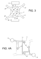
- the Fig. 3 illustrates a mapping of the vibration amplitudes for an electromechanical oscillator 7 in the form of a square plate.
- capacitive excitation means 9 via the electrodes
- Detection means 13 are also used to detect the mechanical response of the oscillator in frequency terms.
- the mechanical responses of the oscillator 7 according to this example show that the corners and the center of the plate constitute vibration nodes 25 (zones of minimum vibration), whereas the middle of the sides of the plate constitute vibration bellies 23 (zones whose amplitude of vibration is maximum).
- the regionalization of the mass response of the oscillator 7 is used to place the trapping site (s) 21 in the zones 23 exhibiting the maximum amplitude of vibration as a function of its geometry and its mode of operation. 'excitation.
- the location of the trapping site 21 within the oscillator 7 allows an efficient coupling between the place corresponding to an optimal mechanical response of mass detection of a particle and trapping. passive fluidics based on segregation by the size of the particle.
- Fig. 3 shows that the support means 27 in the form of arms are distributed at the corners of the square plate in order to minimize the mechanical stresses applied to the resonator during a vibratory cycle. Then, the vibration is not dissipated to the rest of the detection device 3 and is concentrated on the oscillator 7. It will be noted that the arms are also used to pass the connections between the fluidic network 11 and the supply circuit 5 .
- the fluidic network may comprise several trapping sites 21 located on the same vibration belly 23 of the oscillator 7.
- the fluidic network 11 may comprise a plurality of trapping sites 21 situated at the levels of the various vibration bellows 23 of the oscillator 7.
- the trapping sites 21 may be associated in any configuration at the terminals of the supply circuit 5 depending on the intended application. Thus, the trapping sites 21 can be arranged in series, in parallel or in any other configuration combining the two types of associations.
- Figs. 4A and 4B illustrate electromechanical oscillators of recessed cavity plate type having a square shape integrating networks fluidic, in series configuration ( Fig. 4A ) and parallel ( Fig. 4B ).
- the square-shaped oscillator is easy to manufacture and may have a width and a thickness such that the ratio of the width to the thickness is greater than 10, and preferably between 10 and 30.
- This oscillator comprises within it four trapping sites located at the four vibrational levels of the oscillator.
- the trapping sites 21 are arranged in series at the terminals of the supply circuit 5.
- the occupation of the sites 21 is performed sequentially.
- the trapping sites 21 are arranged in parallel across the supply circuit 5, each site 21 being directly connected to the supply circuit 5. In this case, one can have a quasi-simultaneous trapping of the particles.
- the trapping sites 21 may be differently sized to trap particles of different sizes.
- the hollow-recessed plate-type oscillator 7 can be in the form of a disc, a ring, or a polygon.
- the number of vibration bellies 23 depends on the shape of the plate, but also the mode of vibration.
- the oscillator may also have the shape of a cantilever beam, a bi-embedded beam, a nanowire, or a membrane which may possibly be pierced.
- a cantilever beam which vibrates according to the fundamental mode of bending, there is only a belly of vibration at the free summit of the beam which vibrates with the greatest amplitude.
- the excitation means 9 may be chosen from the following means: capacitive, piezoelectric, piezo-metallic, electromagnetic, thermal, thermo-elastic, and optical.
- the fluidic trapping and the maximization of the mass detector response according to the invention are independent of the excitation mode and thus makes it possible to choose the most appropriate vibratory excitation mode.
- the vibratory mode can be chosen according to the type of the oscillator 7 and the intended application.
- the vibratory mode can be taken in the set consisting of a vibratory mode of volume (extensional), a mode of contour of Lamé, a vibratory mode called "wine glass” (wine-glass), a vibratory mode of torsion, vibratory mode of bending, and a mode of membrane.
- the detection means 13 may also be chosen independently from the following means: capacitive, piezoelectric, piezo-metallic, piezoresistive, thermoelastic, and optical.
- the Fig. 5 illustrates a detection device in which the supply circuit comprises supply channels according to a preferred embodiment of the invention.
- the supply circuit 5 comprises first and second supply channels 51, 52 (or bypass channels) whose sections are in a range of a few hundred microns wide and therefore much larger than those of the channels of the fluidic network 11 which are in a micrometer or nanometer scale.
- the upstream end 511 of the first supply channel 51 is connected to a first fluidic inlet 53 and its downstream end 513 is connected to a first fluidic outlet 54.
- the upstream ends 521 and downstream 523 of the second supply channel 52 are connected to second fluid inlet 56 and outlet 57 respectively.
- the inputs and outputs are interchangeable (that is, a mouthpiece can function as an input or an output, depending on the use of the device).
- the first and second supply channels are separated from each other by the fluidic network.
- the fluidic network 11 is then a central network which is in communication on the one hand with the first supply channel 51 and on the other hand with the second supply channel 52 so that the flow in the fluidic network is controllable by a rate adjustment in the first and second supply channels.
- the first and second supply channels 51, 52 are advantageously mounted substantially symmetrically with respect to the central fluidic network 11.
- the first and second supply channels 51, 52 make it possible to adjust the flow in the central fluidic network 11 in a precise and simple manner. Indeed, it is possible to adjust the flow rate in each of the supply channels 51, 52 and the flow differential between the two channels 51, 52 makes it possible to very finely control the flow rate in the central fluidic network 11.
- first and second supply channels 51, 52 which are of large section relative to the central fluidic network 11 can be quickly drained thus making it possible to renew the solutions of interest in an easy manner.
- a small section conduit involves the need to increase the pressure difference between upstream and downstream to maintain a high flow rate to drain), which would have taken much more time and where moreover, there would have been risks of blockage or obstruction.
- the trapping sites 21 are associated in series but of course they can also be associated in parallel (see Fig. 4B ) or in any other configuration.
- the supply and the fluid control control can be provided by a flow type syringe 63 flow generator (see Fig. 6 ).
- the control and supply of the fluid can be provided by a pressure generator (not shown) of the pressurized bottle type.
- a supply circuit 5 comprising a single fluidic inlet and a single fluidic outlet with the fluidic network in direct communication between the fluidic inlet and the fluidic outlet (see FIG. Figs. 4A , 4B ).
- the detection device according to the invention may comprise a set of electromechanical oscillators 7 of the same or different scales. connected in series or in parallel across the terminals of the supply circuit 5.
- Figs. 6A and 6B illustrate a detection device comprising a series of electromechanical oscillators of different scales according to preferred embodiments of the invention.
- Each of the electromechanical oscillators 7a-7c integrates a fluidic network 11a-11c of a corresponding scale and the different fluidic networks 11a-11c are in communication with the first and second supply channels 51, 52.
- the various fluidic networks 11a-11c are connected in shunt between the first and second supply channels 51, 52.
- a distribution of liquid samples in parallel configuration can pass through the fluidic networks 11a-11c of particle trapping of the largest size to the smallest size (as represented on the Fig. 6A ) or conversely (not shown), by introducing a filtration module between the supply circuit and the fluidic networks 11a-11c.
- the various fluidic networks 11a-11c can selectively trap particles of variable sizes present in the fluid corresponding to the solution of interest 61 fed by the power generator 63. This is particularly interesting for samples or solutions of interest Serum type hosting several species of particles of very different sizes.
- a first fluidic network 11a can be dimensionally configured to trap cells of 10 ⁇ m sizes - 100 ⁇ m
- a second fluidic network 11b may be dimensionally configured to trap sizes bacteria 0,5 ⁇ m - 5 ⁇ m
- a third fluidic network 11c may be dimensionally configured to trap sizes of 10 nm virus - 400 nm.
- each of the first and second feed channels 51, 52 has a constant section. Indeed, it is quite practical for reasons of manufacture and emptying to have supply channels of the same section all along the channels.
- each of the first and second feed channels 51, 52 may be formed of a set of sections 51a-51c , 52a-52c of different sections. This makes it possible to maintain the same ratio of hydraulic resistances between the supply sections 51a-51c, 52a-52c and those of the central network 11a-11c. Thus, it is possible to vary the order of magnitude of the hydraulic resistances of the supply channels as a function of the scale of the fluidic network in order to better regulate the flow rates in the different networks 11a-11c.
- each of the power supply channels can comprise only two sections: a first section connected to the microfluidic networks and a second section of smaller section connected to the nanofluidic networks making it possible to increase the flow range for the smaller fluidic networks.
- a method for mass detection of particles in a fluid medium consists in implement the detection device 3 described above.
- This implementation comprises feeding the fluidic network (s) 11a-11c with a solution of interest 61 via the supply channels 51, 52 so that target particles are trapped. in the oscillator.
- the excitation means 9 are used to vibrate the oscillator (s) 7a-7c at their respective resonant frequencies.
- the detection means 13 is used to detect any shift of the resonant frequency with respect to a reference frequency indicative of particle trapping (s).
- reference frequency for example means a resonant frequency determined beforehand. It can in particular be a resonant frequency before supplying the fluidic network with the solution of interest ("vacuum" resonator), or a resonance frequency during the supply of the network with the solution of interest, but measured at an earlier time.
- Signals or trapping peaks can be observed on the display means 17 indicating the occupation of the different trapping sites 21.
Landscapes
- Chemical & Material Sciences (AREA)
- Physics & Mathematics (AREA)
- General Physics & Mathematics (AREA)
- Health & Medical Sciences (AREA)
- Life Sciences & Earth Sciences (AREA)
- Analytical Chemistry (AREA)
- Biochemistry (AREA)
- General Health & Medical Sciences (AREA)
- Immunology (AREA)
- Pathology (AREA)
- Dispersion Chemistry (AREA)
- Apparatus Associated With Microorganisms And Enzymes (AREA)
Applications Claiming Priority (1)
| Application Number | Priority Date | Filing Date | Title |
|---|---|---|---|
| FR1158681A FR2980572B1 (fr) | 2011-09-28 | 2011-09-28 | Dispositif de detection massique de particules en milieu fluide et procede de mise en œuvre |
Publications (2)
| Publication Number | Publication Date |
|---|---|
| EP2574885A1 true EP2574885A1 (de) | 2013-04-03 |
| EP2574885B1 EP2574885B1 (de) | 2014-04-09 |
Family
ID=46875699
Family Applications (1)
| Application Number | Title | Priority Date | Filing Date |
|---|---|---|---|
| EP12186095.1A Not-in-force EP2574885B1 (de) | 2011-09-28 | 2012-09-26 | Verfahren und vorrichtung zum bestimmen der masse von partikeln in einem fluid |
Country Status (4)
| Country | Link |
|---|---|
| US (1) | US9182268B2 (de) |
| EP (1) | EP2574885B1 (de) |
| JP (1) | JP2013072876A (de) |
| FR (1) | FR2980572B1 (de) |
Cited By (1)
| Publication number | Priority date | Publication date | Assignee | Title |
|---|---|---|---|---|
| EP4382887A1 (de) | 2022-12-07 | 2024-06-12 | Commissariat à l'énergie atomique et aux énergies alternatives | Verfahren zur zielerkennung mit einem mechanischen oszillator und funktionalisierten partikeln |
Families Citing this family (6)
| Publication number | Priority date | Publication date | Assignee | Title |
|---|---|---|---|---|
| CN110579435B (zh) | 2012-10-15 | 2023-09-26 | 纳诺赛莱克特生物医药股份有限公司 | 颗粒分选的系统、设备和方法 |
| US20140166483A1 (en) * | 2012-12-19 | 2014-06-19 | Queen's University At Kingston | Electrokinetics-assisted sensor |
| WO2015082956A1 (en) * | 2013-12-02 | 2015-06-11 | Commissariat A L'energie Atomique Et Aux Energies Alternatives | System and method for analyzing a gas |
| US10048190B2 (en) | 2015-01-21 | 2018-08-14 | Sbt Instruments Aps | Microfluidic particle analysis device |
| US10571673B2 (en) | 2016-04-15 | 2020-02-25 | University Of Washington | Particle positioning device with periodic dielectric structure |
| CN110274841B (zh) * | 2018-03-15 | 2021-12-24 | 中冶长天国际工程有限责任公司 | 烧结燃料粒度组成检测系统中筛分过程的诊断方法及装置 |
Citations (1)
| Publication number | Priority date | Publication date | Assignee | Title |
|---|---|---|---|---|
| WO2009141516A1 (fr) | 2008-05-20 | 2009-11-26 | Commissariat A L'energie Atomique | Dispositif pour la detection gravimetrique de particules en milieu fluide, comprenant un oscillateur traverse par une veine fluidique, procede de realisation et methode de mise en oeuvre du dispositif. |
Family Cites Families (21)
| Publication number | Priority date | Publication date | Assignee | Title |
|---|---|---|---|---|
| US4897541A (en) * | 1984-05-18 | 1990-01-30 | Luxtron Corporation | Sensors for detecting electromagnetic parameters utilizing resonating elements |
| GB9218659D0 (en) * | 1992-09-01 | 1992-10-21 | Atomic Energy Authority Uk | Aerosol sampler |
| US5915508A (en) * | 1994-04-18 | 1999-06-29 | Minnesota Mining And Manufacturing Company | Tuned mass damper |
| US6799820B1 (en) * | 1999-05-20 | 2004-10-05 | Seiko Epson Corporation | Liquid container having a liquid detecting device |
| US7312085B2 (en) * | 2002-04-01 | 2007-12-25 | Fluidigm Corporation | Microfluidic particle-analysis systems |
| AU2003224817B2 (en) * | 2002-04-01 | 2008-11-06 | Fluidigm Corporation | Microfluidic particle-analysis systems |
| US7157274B2 (en) * | 2002-06-24 | 2007-01-02 | Cytonome, Inc. | Method and apparatus for sorting particles |
| WO2003102737A2 (en) * | 2002-06-04 | 2003-12-11 | Protasis Corporation | Method and device for ultrasonically manipulating particles within a fluid |
| US7735358B2 (en) * | 2003-11-17 | 2010-06-15 | Insitutec, Inc. | Self-sensing tweezer devices and associated methods for micro and nano-scale manipulation and assembly |
| JP4205558B2 (ja) * | 2003-11-20 | 2009-01-07 | 富士通株式会社 | 汚染評価方法、汚染評価装置、露光方法、及び、露光装置 |
| US7918244B2 (en) * | 2005-05-02 | 2011-04-05 | Massachusetts Institute Of Technology | Microfluidic bubble logic devices |
| JP4616123B2 (ja) * | 2005-08-23 | 2011-01-19 | セイコーインスツル株式会社 | 分析用マイクロセンサ |
| US20090053749A1 (en) * | 2006-01-09 | 2009-02-26 | Massachusetts Institute Of Technology | Method and Apparatus for High Throughput Diagnosis of Diseased Cells With Microchannel Devices |
| WO2008024070A1 (en) * | 2006-08-22 | 2008-02-28 | Agency For Science, Technology And Research | Microfluidic filtration unit, device and methods thereof |
| JP2008136475A (ja) * | 2006-11-10 | 2008-06-19 | Univ Waseda | 細胞捕捉装置及びそれを利用した細胞操作方法 |
| KR100883775B1 (ko) * | 2007-03-22 | 2009-02-18 | 명지대학교 산학협력단 | 모세관 전기영동 칩상에 집적된 전기화학적 검출기 및 이의제조방법 |
| JP4900827B2 (ja) * | 2007-11-21 | 2012-03-21 | 財団法人生産技術研究奨励会 | 再セット可能な微小液滴の配列装置 |
| WO2009126352A2 (en) * | 2008-01-24 | 2009-10-15 | Sandia National Laboratories | Novel micropores and methods of making and using thereof |
| FR2931079B1 (fr) * | 2008-05-13 | 2010-07-30 | Commissariat Energie Atomique | Dispositif et procede de separation d'une suspension |
| US8312763B2 (en) * | 2008-10-15 | 2012-11-20 | Massachusetts Institute Of Technology | Method and apparatus for trapping single particles in microfluidic channels |
| FR2982176B1 (fr) | 2011-11-09 | 2014-01-10 | Commissariat Energie Atomique | Dispositif et procede de manipulation des gouttes |
-
2011
- 2011-09-28 FR FR1158681A patent/FR2980572B1/fr not_active Expired - Fee Related
-
2012
- 2012-09-26 EP EP12186095.1A patent/EP2574885B1/de not_active Not-in-force
- 2012-09-27 US US13/628,908 patent/US9182268B2/en not_active Expired - Fee Related
- 2012-09-27 JP JP2012213749A patent/JP2013072876A/ja active Pending
Patent Citations (2)
| Publication number | Priority date | Publication date | Assignee | Title |
|---|---|---|---|---|
| WO2009141516A1 (fr) | 2008-05-20 | 2009-11-26 | Commissariat A L'energie Atomique | Dispositif pour la detection gravimetrique de particules en milieu fluide, comprenant un oscillateur traverse par une veine fluidique, procede de realisation et methode de mise en oeuvre du dispositif. |
| FR2931549A1 (fr) * | 2008-05-20 | 2009-11-27 | Commissariat Energie Atomique | Dispositif pour la detection gravimetrique de particules en milieu fluide, comprenant un oscillateur traverse par une veine fluidique, procede de realisation et methode de mise en oeuvre du dispositif |
Non-Patent Citations (2)
| Title |
|---|
| J. LEE ET AL.: "Toward Attogram Mass Measurements in Solution with Suspended Nanochannel Resonators", NANO LETTERS, vol. 10, 2010, pages 2537 - 2542 |
| W. H. TAN ET AL.: "A trap-and-release integrated microfluidic system for dynamic microarray applications", PROCEEDINGS OF THE NATIONAL ACADEMY OF SCIENCES OF THE UNITED STATES OF AMERICA, vol. 104, 2007, pages 1146 - 1151 |
Cited By (2)
| Publication number | Priority date | Publication date | Assignee | Title |
|---|---|---|---|---|
| EP4382887A1 (de) | 2022-12-07 | 2024-06-12 | Commissariat à l'énergie atomique et aux énergies alternatives | Verfahren zur zielerkennung mit einem mechanischen oszillator und funktionalisierten partikeln |
| FR3143120A1 (fr) | 2022-12-07 | 2024-06-14 | Commissariat à l'Energie Atomique et aux Energies Alternatives | Procédé de détection de cibles à l'aide d'un oscillateur mécanique et de particules fonctionnalisées |
Also Published As
| Publication number | Publication date |
|---|---|
| FR2980572A1 (fr) | 2013-03-29 |
| US20130074586A1 (en) | 2013-03-28 |
| JP2013072876A (ja) | 2013-04-22 |
| EP2574885B1 (de) | 2014-04-09 |
| FR2980572B1 (fr) | 2014-07-04 |
| US9182268B2 (en) | 2015-11-10 |
Similar Documents
| Publication | Publication Date | Title |
|---|---|---|
| EP2574885B1 (de) | Verfahren und vorrichtung zum bestimmen der masse von partikeln in einem fluid | |
| EP2750778B1 (de) | Vorrichtungen und verfahren zur handhabung von gegenständen mittels akustischer kraftfelder | |
| Barton et al. | Fabrication of a nanomechanical mass sensor containing a nanofluidic channel | |
| Zhu et al. | Self-focused AlScN film ultrasound transducer for individual cell manipulation | |
| Bargatin et al. | Large-scale integration of nanoelectromechanical systems for gas sensing applications | |
| EP3509214A1 (de) | Mikro- oder nanomechanische vorrichtung zur detektion von partikeln | |
| Surappa et al. | Dynamically reconfigurable acoustofluidic metasurface for subwavelength particle manipulation and assembly | |
| US9291600B2 (en) | Piezoresistive NEMS array network | |
| Beardslee et al. | Liquid-phase chemical sensing using lateral mode resonant cantilevers | |
| EP4168791B1 (de) | Eingetauchter umweltsensor mit mitteln gegen verschmutzung | |
| US20150285784A1 (en) | Serial Arrays of Suspended Microchannel Resonators | |
| EP2882101B1 (de) | Verfahren zum Erfassen einer Störung durch einen Hysteresezyklus mit Hilfe eines nicht-linearen elektromechanischen Resonators, und Vorrichtung, die dieses Verfahren anwendet | |
| WO2009141515A1 (fr) | Dispositif pour la detection gravimetrique de particules en milieu fluide comprenant un oscillateur entre deux canaux fluidiques, procede de realisation et methode de mise en oeuvre du dispositif | |
| EP4481377A1 (de) | System und verfahren zur messung mindestens einer eigenschaft eines partikels mit einem mechanischen resonator und einem mechanisch gekoppelten gravimetrischen sensor | |
| EP2286192B1 (de) | Einrichtung zur gravimetrischen detektion von teilchen in einem fluiden medium, verfahren zur gravimetrischen detektion, verfahren zur bestimmung der kinetik der wechselwirkung | |
| EP4532680B1 (de) | Vorrichtung zum erfassen eines biologischen objekts sowie verfahren und system zum analysieren eines biologischen objekts mit der erfassungsvorrichtung | |
| WO2015020611A1 (en) | A multi-mode mems aerosol detecting device | |
| EP4448791A1 (de) | Vorrichtung zur sequenzierung einer nukleotidsequenz mit erhöhter empfindlichkeit und verbesserter zuverlässigkeit | |
| EP4382887B1 (de) | Verfahren zur zielerkennung mit einem mechanischen oszillator und funktionalisierten partikeln | |
| Oliver et al. | Resonantly excited AlN-based microcantilevers for immunosensing | |
| FR3085482A1 (fr) | Capteur de particules fines avec microbalances en cascade | |
| Beardslee et al. | In-plane mode resonant cantilevers as liquid phase chemical sensors with ppb range limits of detection | |
| Mohammadi et al. | Finite Element Simulation of Accelerated Stress Testing and Damage Detection for Micro and Nano Structures Using Surface Acoustic Waves (SAWs) | |
| FR3083606A1 (fr) | Gyrometre micromecanique resonant performant a encombrement reduit | |
| van Dam | Department of Precision and Microsystems Engineering |
Legal Events
| Date | Code | Title | Description |
|---|---|---|---|
| PUAI | Public reference made under article 153(3) epc to a published international application that has entered the european phase |
Free format text: ORIGINAL CODE: 0009012 |
|
| AK | Designated contracting states |
Kind code of ref document: A1 Designated state(s): AL AT BE BG CH CY CZ DE DK EE ES FI FR GB GR HR HU IE IS IT LI LT LU LV MC MK MT NL NO PL PT RO RS SE SI SK SM TR |
|
| AX | Request for extension of the european patent |
Extension state: BA ME |
|
| 17P | Request for examination filed |
Effective date: 20130909 |
|
| RBV | Designated contracting states (corrected) |
Designated state(s): AL AT BE BG CH CY CZ DE DK EE ES FI FR GB GR HR HU IE IS IT LI LT LU LV MC MK MT NL NO PL PT RO RS SE SI SK SM TR |
|
| REG | Reference to a national code |
Ref country code: DE Ref legal event code: R079 Ref document number: 602012001359 Country of ref document: DE Free format text: PREVIOUS MAIN CLASS: G01G0003160000 Ipc: G01N0005000000 |
|
| RIC1 | Information provided on ipc code assigned before grant |
Ipc: G01N 5/00 20060101AFI20131024BHEP |
|
| GRAP | Despatch of communication of intention to grant a patent |
Free format text: ORIGINAL CODE: EPIDOSNIGR1 |
|
| INTG | Intention to grant announced |
Effective date: 20131202 |
|
| GRAS | Grant fee paid |
Free format text: ORIGINAL CODE: EPIDOSNIGR3 |
|
| GRAA | (expected) grant |
Free format text: ORIGINAL CODE: 0009210 |
|
| AK | Designated contracting states |
Kind code of ref document: B1 Designated state(s): AL AT BE BG CH CY CZ DE DK EE ES FI FR GB GR HR HU IE IS IT LI LT LU LV MC MK MT NL NO PL PT RO RS SE SI SK SM TR |
|
| REG | Reference to a national code |
Ref country code: GB Ref legal event code: FG4D Free format text: NOT ENGLISH |
|
| REG | Reference to a national code |
Ref country code: CH Ref legal event code: EP Ref country code: AT Ref legal event code: REF Ref document number: 661596 Country of ref document: AT Kind code of ref document: T Effective date: 20140415 |
|
| REG | Reference to a national code |
Ref country code: IE Ref legal event code: FG4D Free format text: LANGUAGE OF EP DOCUMENT: FRENCH |
|
| REG | Reference to a national code |
Ref country code: DE Ref legal event code: R096 Ref document number: 602012001359 Country of ref document: DE Effective date: 20140522 |
|
| REG | Reference to a national code |
Ref country code: AT Ref legal event code: MK05 Ref document number: 661596 Country of ref document: AT Kind code of ref document: T Effective date: 20140409 |
|
| REG | Reference to a national code |
Ref country code: NL Ref legal event code: VDEP Effective date: 20140409 |
|
| REG | Reference to a national code |
Ref country code: LT Ref legal event code: MG4D |
|
| PG25 | Lapsed in a contracting state [announced via postgrant information from national office to epo] |
Ref country code: GR Free format text: LAPSE BECAUSE OF FAILURE TO SUBMIT A TRANSLATION OF THE DESCRIPTION OR TO PAY THE FEE WITHIN THE PRESCRIBED TIME-LIMIT Effective date: 20140710 Ref country code: FI Free format text: LAPSE BECAUSE OF FAILURE TO SUBMIT A TRANSLATION OF THE DESCRIPTION OR TO PAY THE FEE WITHIN THE PRESCRIBED TIME-LIMIT Effective date: 20140409 Ref country code: IS Free format text: LAPSE BECAUSE OF FAILURE TO SUBMIT A TRANSLATION OF THE DESCRIPTION OR TO PAY THE FEE WITHIN THE PRESCRIBED TIME-LIMIT Effective date: 20140809 Ref country code: LT Free format text: LAPSE BECAUSE OF FAILURE TO SUBMIT A TRANSLATION OF THE DESCRIPTION OR TO PAY THE FEE WITHIN THE PRESCRIBED TIME-LIMIT Effective date: 20140409 Ref country code: NL Free format text: LAPSE BECAUSE OF FAILURE TO SUBMIT A TRANSLATION OF THE DESCRIPTION OR TO PAY THE FEE WITHIN THE PRESCRIBED TIME-LIMIT Effective date: 20140409 Ref country code: BG Free format text: LAPSE BECAUSE OF FAILURE TO SUBMIT A TRANSLATION OF THE DESCRIPTION OR TO PAY THE FEE WITHIN THE PRESCRIBED TIME-LIMIT Effective date: 20140709 Ref country code: NO Free format text: LAPSE BECAUSE OF FAILURE TO SUBMIT A TRANSLATION OF THE DESCRIPTION OR TO PAY THE FEE WITHIN THE PRESCRIBED TIME-LIMIT Effective date: 20140709 |
|
| PG25 | Lapsed in a contracting state [announced via postgrant information from national office to epo] |
Ref country code: HR Free format text: LAPSE BECAUSE OF FAILURE TO SUBMIT A TRANSLATION OF THE DESCRIPTION OR TO PAY THE FEE WITHIN THE PRESCRIBED TIME-LIMIT Effective date: 20140409 Ref country code: RS Free format text: LAPSE BECAUSE OF FAILURE TO SUBMIT A TRANSLATION OF THE DESCRIPTION OR TO PAY THE FEE WITHIN THE PRESCRIBED TIME-LIMIT Effective date: 20140409 Ref country code: AT Free format text: LAPSE BECAUSE OF FAILURE TO SUBMIT A TRANSLATION OF THE DESCRIPTION OR TO PAY THE FEE WITHIN THE PRESCRIBED TIME-LIMIT Effective date: 20140409 Ref country code: PL Free format text: LAPSE BECAUSE OF FAILURE TO SUBMIT A TRANSLATION OF THE DESCRIPTION OR TO PAY THE FEE WITHIN THE PRESCRIBED TIME-LIMIT Effective date: 20140409 Ref country code: LV Free format text: LAPSE BECAUSE OF FAILURE TO SUBMIT A TRANSLATION OF THE DESCRIPTION OR TO PAY THE FEE WITHIN THE PRESCRIBED TIME-LIMIT Effective date: 20140409 Ref country code: ES Free format text: LAPSE BECAUSE OF FAILURE TO SUBMIT A TRANSLATION OF THE DESCRIPTION OR TO PAY THE FEE WITHIN THE PRESCRIBED TIME-LIMIT Effective date: 20140409 Ref country code: SE Free format text: LAPSE BECAUSE OF FAILURE TO SUBMIT A TRANSLATION OF THE DESCRIPTION OR TO PAY THE FEE WITHIN THE PRESCRIBED TIME-LIMIT Effective date: 20140409 |
|
| PG25 | Lapsed in a contracting state [announced via postgrant information from national office to epo] |
Ref country code: PT Free format text: LAPSE BECAUSE OF FAILURE TO SUBMIT A TRANSLATION OF THE DESCRIPTION OR TO PAY THE FEE WITHIN THE PRESCRIBED TIME-LIMIT Effective date: 20140811 |
|
| REG | Reference to a national code |
Ref country code: DE Ref legal event code: R097 Ref document number: 602012001359 Country of ref document: DE |
|
| PG25 | Lapsed in a contracting state [announced via postgrant information from national office to epo] |
Ref country code: DK Free format text: LAPSE BECAUSE OF FAILURE TO SUBMIT A TRANSLATION OF THE DESCRIPTION OR TO PAY THE FEE WITHIN THE PRESCRIBED TIME-LIMIT Effective date: 20140409 Ref country code: CZ Free format text: LAPSE BECAUSE OF FAILURE TO SUBMIT A TRANSLATION OF THE DESCRIPTION OR TO PAY THE FEE WITHIN THE PRESCRIBED TIME-LIMIT Effective date: 20140409 Ref country code: SK Free format text: LAPSE BECAUSE OF FAILURE TO SUBMIT A TRANSLATION OF THE DESCRIPTION OR TO PAY THE FEE WITHIN THE PRESCRIBED TIME-LIMIT Effective date: 20140409 Ref country code: EE Free format text: LAPSE BECAUSE OF FAILURE TO SUBMIT A TRANSLATION OF THE DESCRIPTION OR TO PAY THE FEE WITHIN THE PRESCRIBED TIME-LIMIT Effective date: 20140409 Ref country code: RO Free format text: LAPSE BECAUSE OF FAILURE TO SUBMIT A TRANSLATION OF THE DESCRIPTION OR TO PAY THE FEE WITHIN THE PRESCRIBED TIME-LIMIT Effective date: 20140409 |
|
| PLBE | No opposition filed within time limit |
Free format text: ORIGINAL CODE: 0009261 |
|
| STAA | Information on the status of an ep patent application or granted ep patent |
Free format text: STATUS: NO OPPOSITION FILED WITHIN TIME LIMIT |
|
| 26N | No opposition filed |
Effective date: 20150112 |
|
| PG25 | Lapsed in a contracting state [announced via postgrant information from national office to epo] |
Ref country code: IT Free format text: LAPSE BECAUSE OF FAILURE TO SUBMIT A TRANSLATION OF THE DESCRIPTION OR TO PAY THE FEE WITHIN THE PRESCRIBED TIME-LIMIT Effective date: 20140409 |
|
| REG | Reference to a national code |
Ref country code: DE Ref legal event code: R097 Ref document number: 602012001359 Country of ref document: DE Effective date: 20150112 |
|
| PG25 | Lapsed in a contracting state [announced via postgrant information from national office to epo] |
Ref country code: MC Free format text: LAPSE BECAUSE OF FAILURE TO SUBMIT A TRANSLATION OF THE DESCRIPTION OR TO PAY THE FEE WITHIN THE PRESCRIBED TIME-LIMIT Effective date: 20140409 Ref country code: LU Free format text: LAPSE BECAUSE OF FAILURE TO SUBMIT A TRANSLATION OF THE DESCRIPTION OR TO PAY THE FEE WITHIN THE PRESCRIBED TIME-LIMIT Effective date: 20140926 |
|
| REG | Reference to a national code |
Ref country code: IE Ref legal event code: MM4A |
|
| PG25 | Lapsed in a contracting state [announced via postgrant information from national office to epo] |
Ref country code: BE Free format text: LAPSE BECAUSE OF NON-PAYMENT OF DUE FEES Effective date: 20140930 |
|
| PG25 | Lapsed in a contracting state [announced via postgrant information from national office to epo] |
Ref country code: SI Free format text: LAPSE BECAUSE OF FAILURE TO SUBMIT A TRANSLATION OF THE DESCRIPTION OR TO PAY THE FEE WITHIN THE PRESCRIBED TIME-LIMIT Effective date: 20140409 |
|
| PG25 | Lapsed in a contracting state [announced via postgrant information from national office to epo] |
Ref country code: IE Free format text: LAPSE BECAUSE OF NON-PAYMENT OF DUE FEES Effective date: 20140926 |
|
| REG | Reference to a national code |
Ref country code: CH Ref legal event code: PL |
|
| PG25 | Lapsed in a contracting state [announced via postgrant information from national office to epo] |
Ref country code: SM Free format text: LAPSE BECAUSE OF FAILURE TO SUBMIT A TRANSLATION OF THE DESCRIPTION OR TO PAY THE FEE WITHIN THE PRESCRIBED TIME-LIMIT Effective date: 20140409 |
|
| PG25 | Lapsed in a contracting state [announced via postgrant information from national office to epo] |
Ref country code: CY Free format text: LAPSE BECAUSE OF FAILURE TO SUBMIT A TRANSLATION OF THE DESCRIPTION OR TO PAY THE FEE WITHIN THE PRESCRIBED TIME-LIMIT Effective date: 20140409 Ref country code: MT Free format text: LAPSE BECAUSE OF FAILURE TO SUBMIT A TRANSLATION OF THE DESCRIPTION OR TO PAY THE FEE WITHIN THE PRESCRIBED TIME-LIMIT Effective date: 20140409 |
|
| PG25 | Lapsed in a contracting state [announced via postgrant information from national office to epo] |
Ref country code: LI Free format text: LAPSE BECAUSE OF NON-PAYMENT OF DUE FEES Effective date: 20150930 Ref country code: HU Free format text: LAPSE BECAUSE OF FAILURE TO SUBMIT A TRANSLATION OF THE DESCRIPTION OR TO PAY THE FEE WITHIN THE PRESCRIBED TIME-LIMIT; INVALID AB INITIO Effective date: 20120926 Ref country code: TR Free format text: LAPSE BECAUSE OF FAILURE TO SUBMIT A TRANSLATION OF THE DESCRIPTION OR TO PAY THE FEE WITHIN THE PRESCRIBED TIME-LIMIT Effective date: 20140409 Ref country code: CH Free format text: LAPSE BECAUSE OF NON-PAYMENT OF DUE FEES Effective date: 20150930 |
|
| REG | Reference to a national code |
Ref country code: FR Ref legal event code: PLFP Year of fee payment: 5 |
|
| REG | Reference to a national code |
Ref country code: FR Ref legal event code: PLFP Year of fee payment: 6 |
|
| PG25 | Lapsed in a contracting state [announced via postgrant information from national office to epo] |
Ref country code: MK Free format text: LAPSE BECAUSE OF FAILURE TO SUBMIT A TRANSLATION OF THE DESCRIPTION OR TO PAY THE FEE WITHIN THE PRESCRIBED TIME-LIMIT Effective date: 20140409 |
|
| REG | Reference to a national code |
Ref country code: FR Ref legal event code: PLFP Year of fee payment: 7 |
|
| PG25 | Lapsed in a contracting state [announced via postgrant information from national office to epo] |
Ref country code: AL Free format text: LAPSE BECAUSE OF FAILURE TO SUBMIT A TRANSLATION OF THE DESCRIPTION OR TO PAY THE FEE WITHIN THE PRESCRIBED TIME-LIMIT Effective date: 20140409 |
|
| PGFP | Annual fee paid to national office [announced via postgrant information from national office to epo] |
Ref country code: FR Payment date: 20180928 Year of fee payment: 7 Ref country code: DE Payment date: 20180913 Year of fee payment: 7 |
|
| PGFP | Annual fee paid to national office [announced via postgrant information from national office to epo] |
Ref country code: GB Payment date: 20180919 Year of fee payment: 7 |
|
| REG | Reference to a national code |
Ref country code: DE Ref legal event code: R119 Ref document number: 602012001359 Country of ref document: DE |
|
| PG25 | Lapsed in a contracting state [announced via postgrant information from national office to epo] |
Ref country code: DE Free format text: LAPSE BECAUSE OF NON-PAYMENT OF DUE FEES Effective date: 20200401 |
|
| GBPC | Gb: european patent ceased through non-payment of renewal fee |
Effective date: 20190926 |
|
| PG25 | Lapsed in a contracting state [announced via postgrant information from national office to epo] |
Ref country code: FR Free format text: LAPSE BECAUSE OF NON-PAYMENT OF DUE FEES Effective date: 20190930 Ref country code: GB Free format text: LAPSE BECAUSE OF NON-PAYMENT OF DUE FEES Effective date: 20190926 |