EP2574892A2 - Circuits pour déterminer des températures moyennes et différentielles à partir de dispositifs de température résistifs - Google Patents
Circuits pour déterminer des températures moyennes et différentielles à partir de dispositifs de température résistifs Download PDFInfo
- Publication number
- EP2574892A2 EP2574892A2 EP12185926A EP12185926A EP2574892A2 EP 2574892 A2 EP2574892 A2 EP 2574892A2 EP 12185926 A EP12185926 A EP 12185926A EP 12185926 A EP12185926 A EP 12185926A EP 2574892 A2 EP2574892 A2 EP 2574892A2
- Authority
- EP
- European Patent Office
- Prior art keywords
- node
- temperature
- coupled
- sensing element
- circuit
- Prior art date
- Legal status (The legal status is an assumption and is not a legal conclusion. Google has not performed a legal analysis and makes no representation as to the accuracy of the status listed.)
- Granted
Links
Images


Classifications
-
- G—PHYSICS
- G01—MEASURING; TESTING
- G01K—MEASURING TEMPERATURE; MEASURING QUANTITY OF HEAT; THERMALLY-SENSITIVE ELEMENTS NOT OTHERWISE PROVIDED FOR
- G01K3/00—Thermometers giving results other than momentary value of temperature
- G01K3/02—Thermometers giving results other than momentary value of temperature giving means values; giving integrated values
- G01K3/06—Thermometers giving results other than momentary value of temperature giving means values; giving integrated values in respect of space
-
- G—PHYSICS
- G01—MEASURING; TESTING
- G01C—MEASURING DISTANCES, LEVELS OR BEARINGS; SURVEYING; NAVIGATION; GYROSCOPIC INSTRUMENTS; PHOTOGRAMMETRY OR VIDEOGRAMMETRY
- G01C19/00—Gyroscopes; Turn-sensitive devices using vibrating masses; Turn-sensitive devices without moving masses; Measuring angular rate using gyroscopic effects
- G01C19/58—Turn-sensitive devices without moving masses
- G01C19/64—Gyrometers using the Sagnac effect, i.e. rotation-induced shifts between counter-rotating electromagnetic beams
- G01C19/66—Ring laser gyrometers
- G01C19/661—Ring laser gyrometers details
-
- G—PHYSICS
- G01—MEASURING; TESTING
- G01K—MEASURING TEMPERATURE; MEASURING QUANTITY OF HEAT; THERMALLY-SENSITIVE ELEMENTS NOT OTHERWISE PROVIDED FOR
- G01K3/00—Thermometers giving results other than momentary value of temperature
- G01K3/08—Thermometers giving results other than momentary value of temperature giving differences of values; giving differentiated values
- G01K3/14—Thermometers giving results other than momentary value of temperature giving differences of values; giving differentiated values in respect of space
-
- G—PHYSICS
- G01—MEASURING; TESTING
- G01K—MEASURING TEMPERATURE; MEASURING QUANTITY OF HEAT; THERMALLY-SENSITIVE ELEMENTS NOT OTHERWISE PROVIDED FOR
- G01K7/00—Measuring temperature based on the use of electric or magnetic elements directly sensitive to heat ; Power supply therefor, e.g. using thermoelectric elements
- G01K7/16—Measuring temperature based on the use of electric or magnetic elements directly sensitive to heat ; Power supply therefor, e.g. using thermoelectric elements using resistive elements
- G01K7/22—Measuring temperature based on the use of electric or magnetic elements directly sensitive to heat ; Power supply therefor, e.g. using thermoelectric elements using resistive elements the element being a non-linear resistance, e.g. thermistor
- G01K7/24—Measuring temperature based on the use of electric or magnetic elements directly sensitive to heat ; Power supply therefor, e.g. using thermoelectric elements using resistive elements the element being a non-linear resistance, e.g. thermistor in a specially-adapted circuit, e.g. bridge circuit
Definitions
- Resistive temperature devices are devices that have temperature sensing elements that vary in resistance as a function of temperature. Although the output response curves are non-linear in nature, precision temperature measurements can be readily obtained because an RTD's response will predictably follow the response curve. Measuring spatial differences in temperature using a pair of RTDs is challenging however, because simply knowing a difference in the resistances between two RTDs does not convey where either device is with respect to its response curve. As such this difference value cannot be used by itself to determine a temperature difference.
- the embodiments of the present invention provide circuits for determining differential and average temperatures from resistive temperature devices and will be understood by reading and studying the following specification.
- a device comprises a bridge network including a first node and second node, wherein the first node receives a constant current from a current source; a first branch coupled between a first node and a second node, the first branch including a first temperature sensing element of a first resistive temperature device; a second branch coupled in parallel with the first branch between the first node and the second node, the second branch including a second temperature sensing element of a second resistive temperature device; a first output that provides a signal representing a difference between a voltage developed across the first temperature sensing element and a voltage developed across the second temperature sensing element; and a second output that provides a signal representing a voltage developed across first node and the second node.
- Figure 1 is a diagram illustrating one embodiment of the present invention
- Figure 2 is a diagram illustrating one embodiment of the present invention.
- Figure 3 is a diagram illustrating one embodiment of the present invention.
- Embodiments of the present invention provide means to determine accurately, with just a few number of parts, a differential temperature from two non-linear precision RTS temperature sensors (such as a platinum resistive temperature device (RTD), for example) by providing both a differential measurement and an average measurement from the two sensors.
- RTS temperature sensors such as a platinum resistive temperature device (RTD), for example
- FIG. 1 is a simplified diagram of a ring laser gyroscope 100 of one embodiment of the present invention.
- Ring laser gyroscope 100 includes a laser block sensor 110 coupled to processing elements 160.
- laser block sensor 110 is triangular in shape having three sides (106-1, 106-2 and 106-3) and three blunted corners 107-1, 107-2 and 107-3.
- laser block sensor 110 is formed from a different shape laser block sensor such as a four sided square, or a three-axis monolithic laser block. Examples of such are discussed in the H0033109 application herein incorporated by reference.
- Laser block assembly 110 includes three electrodes 101, 102 and 103 each positioned on the respective sides 106-1, 106-2 and 106-3 of the laser block sensor 110.
- electrodes 101 and 102 are cathodes and electrode 103 is an anode.
- the laser block assembly may alternately include two anodes at 101 and 102, and a single cathode at 103.
- Mirrors 104-1, 104-2, and 104-3 are located as shown at the blunted corners 107-1, 107-2 and 107-3 of laser block sensor 110, located between each of the sides 106-1, 106-2 and 106-3.
- a cavity 108 Within laser block sensor 110 is a cavity 108, which in conjunction with the mirrors 104-1, 104-2, and 104-3forms a laser beam path enclosing an area within the laser block sensor 110.
- the performance of ring laser gyroscope 100 is observed by coupling optical energy information from the cavity 108 to a readout assembly 140.
- the readout assembly 140 provides voltage signals to processing elements 160 from which the difference frequency and hence rotation information may be obtained.
- the readout assembly 140 in this embodiment, also provides a voltage signal to processing elements 160 correlated with laser intensity called the Laser Intensity Monitor (LIM) output.
- LIM Laser Intensity Monitor
- This LIM output provides information regarding the optical energy within the cavity 108 of ring laser gyroscope 100.
- cavity 108 is filled with a fill gas mixture 109 of Helium and Neon. In other embodiments, other fill gas mixtures are used within cavity 108.
- Figure 1 illustrates a simplified block diagram that provides sufficient detail to facilitate an enabled written description of embodiments of the present invention. Additional details not shown regarding the physical structure and electronic circuitry associated with a laser block sensor for a ring laser gyroscope are considered within the knowledge and skill of one of ordinary skill in the art and are not discussed herein.
- Ring laser gyroscope 100 further comprises at least one pair of resistive temperature device (RTD) temperature sensors 122a and 122b for calculating a spatial temperature gradient across a defined line 125 that traverses a portion of the laser block sensor 110.
- RTD resistive temperature device
- the defined line 125 is provided for illustrative purposes only and should not be interpreted to limit embodiments of the present invention to only the particular line shown in Figure 1 . In other implementations, line 125 would represent a gradient across any other alternate portion of the laser block sensor 110 with temperature sensors 122a and 122b placed for measuring the spatial temperature gradient across that alternate line appropriately.
- ring laser gyroscope 100 further comprises a temperature sensor 120 for measuring a laser block temperature (T block ) of the laser block sensor 110.
- T block a laser block temperature of the laser block sensor 110.
- values for the laser block temperature (T block ) may be obtained from Ta as measured by temperature sensor 122a, Tb as measured by temperature sensor 122b, or from a combination such as from an average of Ta and Tb.
- Processing elements 160 are coupled to the rotation measurement output 111 of laser block sensor 110, coupled to temperature sensor 120, and coupled to temperature sensors 122a and 122b via circuit 150.
- Processing elements 160 includes a thermal gradient compensation model 162, which receives raw angular rate data ( ⁇ ) generated from the Rotation Information 111 output of laser block sensor 110, laser block temperature measurements, T block (in this particular example provided by sensor 120), and temperature gradient (T diff ) data derived from temperature sensor 122a and 122b measurements. From these parameters, thermal gradient compensation model 162 estimates a Rate Bias Error.
- thermal gradient compensation model 162 comprises a linear regression having a plurality of coefficients (K) that correlate to parameters based on T block and T diff . Examples of such models are described in the H0033109 application, incorporated herein by reference.
- thermal gradient compensation model 162 also utilizes additional parameters (T block 2 , dT block /dt (the time derivative of T block ), and the product T block ⁇ (dT block /dt)) each derived from the laser block temperature measurements (T blo c k ). By subtracting this Rate Bias Error from the angular rate data ( ⁇ ), processing circuitry 160 outputs the bias compensated rate ( ⁇ comp ).
- Temperature sensor 122a provides a first temperature measurement by varying its resistance as a function of the temperature it senses on laser block sensor 110 (denoted as Ta). Temperature sensor 122b provides a second temperature measurement by varying its resistance as a function of the temperature it senses on laser block sensor 110 (denoted at Tb).
- the RTD temperature sensors used for sensors 122a and 122b do not provide a linear output response to changes in temperature. For this reason, the temperature gradient measurements T diff used with thermal gradient compensation model 162 are not simply the difference between Ta and Tb but are instead a function of the difference Ta-Tb that is linearized using an average (Tab avg ) also derived from Ta and Tb.
- FIG. 2 is a schematic of a bridge circuit 150 for one embodiment of the present invention that senses the senses the Ta and Tb measurements from temperature sensors 122a and122b and from them generates two output signals.
- Bridge circuit 150 uses a Wheatstone bridge circuit configuration comprising a stable current source 210 to supply a bridge network 220 which then measures a voltage difference between the two sensors 122a and 122b.
- the first output signal, V a-b , generated by bridge circuit 150 represents a difference between the raw temperatures measurements made by sensors 122a and 122b.
- a second output signal, V T , generated by bridge circuit 150 provides an average of the raw temperatures measurements made by sensors 122a and 122b.
- the average V T is used by processing elements 260 to linearize the difference signal V a-b for the purpose of deriving values for T diff .
- Current source 210 is a precision current source that provides a constant precision current to a first node 224 of bridge network 220.
- Bridge network 220 has a first branch 221a that includes the temperature sensing element 226a of temperature sensor 122a. One end of temperature sensing element 226a is coupled to the first node 224. The other end is coupled to a precision resistor 222a.
- a second branch 221b of bridge network 220 includes the temperature sensing element 226b of temperature sensor 122b. One end of temperature sensing element 226b is coupled to first node 224 and the other end is couple to a second precision resistor 222b. The ends of the first precision resistor 222a and the second precision resistor 222b that are not coupled to the respective sensing elements 226a and 226b are coupled together at the second node 227 of bridge network 220.
- any difference in the current flow between branch 221a verses branch 221b is a function of a difference in the resistances of sensing elements 226a and 226b.
- the first and second precision resistors 222a and 222b are matched so that differences in their resistances do not themselves induce any difference in current flow between the branches.
- a test point in branch 221a (shown as Va) provides a voltage measurement at the junction where the first sensing element 226a is coupled to precision resistor 222a.
- Another test point in branch 221b (shown as Vb) provides a voltage measurement at the junction where the second sensing element 222b is coupled to precision resistor 222b.
- the difference between the voltages at Va and Vb provides the first output of bridge circuit 150 (shown at V a-b ).
- the difference between the voltage at the first node 224 and the second node 227 provides the second output of bridge circuit 150 (shown at V T ).
- current source 210 supplies a constant precision current to first node 224 of bridge network 220 which splits between the parallel branches 221a and 221b and is recombined at second node 227.
- first node 224 of bridge network 220 which splits between the parallel branches 221a and 221b and is recombined at second node 227.
- the resistances in the branches 221a and 221b are equal, the current flowing through each of the branches will each be half of the current supplied to first node 224. Under these conditions, the voltage difference from Va to Vb will be zero.
- V a-b is not directly proportional to the T diff value that reflects the actual temperature gradient in degrees. That is, the value of V a-b must be linearized based on knowledge of the temperature at the laser block sensor 110.
- the second output of bridge circuit 150, V T provides this knowledge.
- the constant current is supplied to the first node 224, the total current supplied to the bridge network 220 is known and constant. Variations that develop in the voltage V T are therefore a function of the total resistance of bridge network 220.
- the voltage V T provides an indication of the average temperature (Tab avg ) being measured at sensing elements 226a and 226b. Accordingly, in one embodiment, the voltage V T is used by processing elements 160 to linearize the voltage V a-b which is then correlated (using the known response curves for sensors 122a and 122b) to a value T diff value that reflects the actual temperature gradient.
- current source 210 comprises a precision DC voltage source 211 coupled to an operational amplifier (“op-amp"), shown at 212 and arranged as a current source with the DC voltage source 211 coupled to the non-inverting input of op-amp 212, the second node 227 of bridge network 220 providing a feedback signal to the inverting input of op-amp 212, and the output of op-amp 212 supplying current to the first node 224 of bridge network 220.
- a bias resistor R2 shown at 214, is placed between the second node 227 and ground in order to limit the current through temperature sensing elements 226a and 226b so as to avoid self heating of those elements.
- R2 can be readily determined by one of ordinary skill in the art after reading this specification by reference to current limit recommendations provided by the manufacturers of temperature sensors 122a and 122b. In one embodiment, R2 is specified such that less than 250 micro-amps will flow through either of sensing element 226a or 226b.
- processing elements 160 include at least one analog-to-digital converter 261 for sampling the outputs V T and V a-b into digital data.
- analog-to-digital converter 261 is a multiplexing analog-to-digital converter with a selectable gain.
- the voltage V a-b may be much smaller in scale as compared to V T .
- analog-to-digital converter 261 will apply a different gain to digital samples generated for V a-b that for digital samples generated for V T .
- a gain of 1 is applied to digital samples for V T while a gain of 128 is applied to digital samples for V a-b .
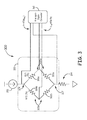
- Figure 3 illustrates a bridge circuit 300 comprising a current source 310 coupled to a bridge network 320, coupled to a bias resistor 314.
- a first branch 321a of bridge network 320 is coupled between a first node 324 and a second node 327 of bridge network 320.
- the first branch includes the temperature sensing element 226a of a first resistive temperature device.
- a second branch 321b is coupled in parallel with the first branch 321a, between the first node 324 and the second node 327.
- the second branch 321b includes a second temperature sensing element 326b from a second resistive temperature device.
- a first output from bridge network 320 (shown as V a-b ) provides an output signal representing a difference between a voltage developed across temperature sensing element 326a and a voltage developed across temperature sensing element 326b.
- a second output from bridge network 320 (shown as V T ) provides an output signal representing the voltage that developed across first node 324 and the second node 327.
- the outputs V T and V a-b from bridge circuit 320 are optionally coupled to at least one analog-to-digital converter 361 that samples the outputs V T and V a-b into digital data for further processing, such as described above, to determine a differential temperature measurement from the measurements from temperature sensing elements 326a and 326b.
- current source 310 supplies a constant precision current to first node 324 of bridge network 320 which splits between the parallel branches 321a and 321b and is recombined at second node 327.
- the resistances in the branches 321a and 321b are equal, the current flowing through each of the branches will each be half of the current supplied to first node 324. Under these conditions, the voltage V a-b will be zero.
- a temperature gradient develops between temperature sensing elements 326a and 326b, the temperatures measured will deviate from each other, causing the resistances of sensing elements 326a and 326b to also deviate from each other.
- V a-b the current supplied to node 324 will no longer be shared equally between branches 321a and 321b and a voltage difference develops which is output from bridge network 320 as V a-b .
- the value of V a-b thus will vary as a function of the difference in temperatures measured by temperature sensing elements 326a and 326b.
- variations that develop in the voltage V T are a function of the total resistance of bridge network 320. Because the two sensing elements 326a and 326b are located in matching parallel branches, the voltage V T provides an indication of the average temperature being measured at sensing elements 326a and 326b.
- Bias resistor 314 performs the same function as described with respect to resistor 214 in Figure 2 , to avoid self heating of the sensing elements 326a and 326b. Bias resistor 314 can be readily determined by one of ordinary skill in the art after reading this specification. In one embodiment, the resistance for bias resistor 314 is specified such that less than 250 micro-amps will flow through either of sensing element 326a or 326b.
- Example 1 includes a circuit comprising: a current source; a bridge network including: a first node and a second node, the first node coupled to the current source; a first branch coupled between the first node and the second node; a second branch coupled in parallel with the first branch between the first node and the second node; wherein the first branch includes a first temperature sensing element of a first resistive temperature device in series with a first resistor; wherein the second branch includes a second temperature sensing element of a second temperature device in series with a second resistor; a first output that provides a signal representing a difference between a voltage developed across the first temperature sensing element and a voltage developed across the second temperature sensing element; and a second output providing a voltage representing a difference in voltage between the first node and the second node.
- Example 2 includes the circuit of Example 1, further comprising a voltage feedback from the second node of the bridge network to the current source.
- Example 3 includes the circuit of any of Examples 1-2, further comprising at least one analog-to-digital converter coupled to the bridge network.
- Example 4 includes the circuit of Example 3, wherein an input of the analog-to-digital converter is coupled to the first output and wherein the analog-to-digital converter output a sample of V a-b.
- Example 5 includes the circuit of any of Examples 3-4, wherein an input of the analog-to-digital converter is coupled to the second output and wherein the analog-to-digital converter outputs a sample of V T .
- Example 6 includes the circuit of any of Examples 3-5, further comprising one or more processing elements, wherein the processing elements input digital samples of V T and digital samples of V a-b and calculate a temperature differential T diff between the first resistive temperature device and the second resistive temperature device from the digital samples of V T and digital samples of V a-b .
- Example 7 includes the circuit of any of Examples 1-6, wherein the current source includes an amplifier comprising: a first input coupled to a DC power source; a second input coupled to the second node of the bridge network; and an output coupled to the first node of the bridge network.
- the current source includes an amplifier comprising: a first input coupled to a DC power source; a second input coupled to the second node of the bridge network; and an output coupled to the first node of the bridge network.
- Example 8 includes the circuit of any of Examples 1-7, further comprising a bias resistor coupled to the second node, the bias resistor generating a feedback to the current source to limit current flow through each of the first temperature sensing element and the second temperature sensing element.
- Example 9 includes the circuit of any of Examples 1-8, wherein the first resistor and the second resistor are matched precision resistors.
- Example 10 includes the circuit of any of Examples 1-9, wherein the first resistive temperature device and the second resistive temperature device are located within a ring laser gyroscope to measure a temperature differential across a laser block sensor.
- Example 11 includes a device comprising: a bridge network including: a first node and a second node, wherein the first node receives a constant current from a current source; a first branch coupled between a first node and a second node, the first branch including a first temperature sensing element of a first resistive temperature device; a second branch coupled in parallel with the first branch between the first node and the second node, the second branch including a second temperature sensing element of a second resistive temperature device; a first output that provides a signal representing a difference between a voltage developed across the first temperature sensing element and a voltage developed across the second temperature sensing element; and a second output that provides a signal representing a voltage developed across first node and the second node.
- Example 12 includes the device of Example 11, the first branch further comprising a first resistor in series with the first temperature sensing element; and the second branch further comprising a second resistor in series with the second temperature sensing element; wherein the first resistor and the second resistor are matched precision resistors.
- Example 13 includes the device of any of Examples 11-12, wherein the current source receives a feedback signal from the second node of the bridge network.
- Example 14 includes the device of Example 13, further comprising a bias resistor sized to limit current flow through each of the first temperature sensing element and the second temperature sensing element to below a threshold.
- Example 15 includes the device of Example 14, wherein the bias resistor is coupled between the second node and ground.
- Example 16 includes the device of any of Examples 11-15, further comprising at least one analog-to-digital converter coupled to the first output and the second output of the bridge network.
- Example 17 includes the device of any of Examples 11-16, further comprising one or more processing elements, wherein the processing elements input digital samples of V T and digital samples of V a-b and calculate a temperature differential T diff between the first resistive temperature device and the second resistive temperature device from the digital samples of V T and digital samples of V a-b .
- Example 18 includes the device of any of Examples 11-17, further comprising the current source, wherein the current source includes an amplifier comprising: a first input coupled to a DC power source; a second input coupled to the second node of the bridge network; and an output coupled to the first node of the bridge network.
- the current source includes an amplifier comprising: a first input coupled to a DC power source; a second input coupled to the second node of the bridge network; and an output coupled to the first node of the bridge network.
- Example 19 includes the device of any of Examples 11-18, wherein the first resistive temperature device and the second resistive temperature device are located within a ring laser gyroscope to measure a temperature differential across a laser block sensor.
Landscapes
- Physics & Mathematics (AREA)
- General Physics & Mathematics (AREA)
- Engineering & Computer Science (AREA)
- Nonlinear Science (AREA)
- Optics & Photonics (AREA)
- Electromagnetism (AREA)
- Power Engineering (AREA)
- Radar, Positioning & Navigation (AREA)
- Remote Sensing (AREA)
- Gyroscopes (AREA)
- Measuring Temperature Or Quantity Of Heat (AREA)
- Measuring Instrument Details And Bridges, And Automatic Balancing Devices (AREA)
Applications Claiming Priority (1)
| Application Number | Priority Date | Filing Date | Title |
|---|---|---|---|
| US13/250,319 US9091598B2 (en) | 2011-09-30 | 2011-09-30 | Circuits for determining differential and average temperatures from resistive temperature devices |
Publications (3)
| Publication Number | Publication Date |
|---|---|
| EP2574892A2 true EP2574892A2 (fr) | 2013-04-03 |
| EP2574892A3 EP2574892A3 (fr) | 2014-03-19 |
| EP2574892B1 EP2574892B1 (fr) | 2016-02-24 |
Family
ID=47221941
Family Applications (1)
| Application Number | Title | Priority Date | Filing Date |
|---|---|---|---|
| EP12185926.8A Active EP2574892B1 (fr) | 2011-09-30 | 2012-09-25 | Circuits pour déterminer des températures moyennes et différentielles à partir de dispositifs de température résistifs |
Country Status (2)
| Country | Link |
|---|---|
| US (1) | US9091598B2 (fr) |
| EP (1) | EP2574892B1 (fr) |
Cited By (1)
| Publication number | Priority date | Publication date | Assignee | Title |
|---|---|---|---|---|
| CN104296735A (zh) * | 2013-11-29 | 2015-01-21 | 中国航空工业集团公司洛阳电光设备研究所 | 一种动力调谐陀螺仪信号器测量电路 |
Families Citing this family (3)
| Publication number | Priority date | Publication date | Assignee | Title |
|---|---|---|---|---|
| US8905635B2 (en) * | 2011-09-30 | 2014-12-09 | Honeywell International Inc. | Temperature sensor attachment facilitating thermal conductivity to a measurement point and insulation from a surrounding environment |
| EP2762867B1 (fr) * | 2013-01-31 | 2018-11-21 | Sensirion AG | Capteur de gaz avec régulation de température |
| CN115824333B (zh) * | 2022-12-28 | 2026-01-30 | 山东核电有限公司 | 热式气体质量流量计的介质温度的检测电路、方法及设备 |
Family Cites Families (29)
| Publication number | Priority date | Publication date | Assignee | Title |
|---|---|---|---|---|
| US3186229A (en) | 1961-09-26 | 1965-06-01 | Liben William | Temperature-sensitive device |
| US3469922A (en) * | 1967-03-27 | 1969-09-30 | Massachusetts Inst Technology | Gas ring laser gyroscope system |
| US3683671A (en) * | 1970-09-14 | 1972-08-15 | Univ Kansas State | Measuring system including thermal conductivity detector means |
| US3967188A (en) * | 1973-05-24 | 1976-06-29 | Bell & Howell Company | Temperature compensation circuit for sensor of physical variables such as temperature and pressure |
| US4035081A (en) * | 1974-12-21 | 1977-07-12 | Messerschmitt-Bolkow-Blohm Gmbh | Laser gyroscope |
| US4143549A (en) | 1978-01-27 | 1979-03-13 | The United States Of America As Represented By The Secretary Of The Navy | Temperature measuring system |
| US4282753A (en) | 1980-03-31 | 1981-08-11 | The United States Of America As Represented By The Secretary Of Transportation | Combination absolute and differential temperature system |
| US4411527A (en) | 1981-06-29 | 1983-10-25 | The Singer Company | Ring laser gyroscope with compensation |
| US4722406A (en) * | 1985-06-21 | 1988-02-02 | Ishida Scales Mfg. Co. Ltd. | Electronic weigher with compensated test signal |
| US4867567A (en) | 1987-08-21 | 1989-09-19 | Litton Systems, Inc. | Ring laser gyro frame design resistant to thermal gradient effects |
| DE69124820T2 (de) * | 1990-04-26 | 1997-07-24 | Hitachi Cable | Optischer Faserkreisel |
| RU2008633C1 (ru) * | 1991-04-04 | 1994-02-28 | Научно-производственное объединение "Техномаш" | Устройство для измерения температуры |
| US5546482A (en) | 1993-04-19 | 1996-08-13 | Litton Systems, Inc. | Potted fiber optic gyro sensor coil for stringent vibration and thermal enviroments |
| US5400141A (en) | 1993-08-31 | 1995-03-21 | Honeywell Inc. | Method and system for minimizing angular random walk or bias in a ring laser gyroscope through the use of temperature based control |
| JPH09505668A (ja) | 1993-11-29 | 1997-06-03 | ハネウエル・インコーポレーテッド | モジュール式レーザ・ジャイロ |
| US5601363A (en) * | 1994-06-09 | 1997-02-11 | Caterpillar Inc. | Quench system cooling effectiveness meter and method of operating same |
| US5786895A (en) * | 1996-03-11 | 1998-07-28 | Litton Systems, Inc. | Means and method for active dispersion equalization of a multioscillator ring laser gyroscope |
| US6889152B2 (en) * | 1997-12-24 | 2005-05-03 | Edward S. More | Method and apparatus for economical drift compensation in high resolution measurements |
| US7014357B2 (en) * | 2002-11-19 | 2006-03-21 | Rosemount Aerospace Inc. | Thermal icing conditions detector |
| GB0227098D0 (en) | 2002-11-20 | 2002-12-24 | Bae Systems Plc | Method of calibrating bias drift with temperature for a vibrating structure gyroscope |
| US7068700B2 (en) * | 2003-11-14 | 2006-06-27 | Honeywell International Inc. | Optical bench for diode-pumped solid state lasers in field applications |
| US7483795B2 (en) * | 2004-08-10 | 2009-01-27 | Robertshaw Controls Company | Pressure and temperature compensation algorithm for use with a piezo-resistive strain gauge type pressure sensor |
| US7191072B2 (en) * | 2004-08-10 | 2007-03-13 | Robertshaw Controls Company | Pressure and temperature measurement of a piezo-resistive device using differential channel of a ratiometric analog to digital converter |
| CN100494897C (zh) | 2006-12-31 | 2009-06-03 | 中国航天时代电子公司 | 采用低偏和保偏混合光路的光纤陀螺 |
| CN101349560B (zh) * | 2008-07-07 | 2011-07-06 | 北京信息工程学院 | 水平姿态敏感芯片及其制造方法、水平姿态传感器 |
| DE102009028958A1 (de) | 2009-08-28 | 2011-03-03 | Robert Bosch Gmbh | Magnetfeld- und Temperatursensor mit einer Wheatstoneschen Widerstands-Messbrücke und Verfahren zur Messung von Magnetfeld und Temperatur |
| US8504311B2 (en) * | 2010-04-09 | 2013-08-06 | Hitachi Metals, Ltd. | Method and mass flow controller for enhanced operating range |
| US8432551B2 (en) * | 2010-08-06 | 2013-04-30 | Honeywell International Inc. | Neon or iodine absorption enhanced hene ring laser gyroscope |
| US8781778B2 (en) * | 2011-09-30 | 2014-07-15 | Honeywell International Inc. | Systems and methods for thermal gradient compensation for ring laser gyroscopes |
-
2011
- 2011-09-30 US US13/250,319 patent/US9091598B2/en active Active
-
2012
- 2012-09-25 EP EP12185926.8A patent/EP2574892B1/fr active Active
Non-Patent Citations (1)
| Title |
|---|
| None |
Cited By (1)
| Publication number | Priority date | Publication date | Assignee | Title |
|---|---|---|---|---|
| CN104296735A (zh) * | 2013-11-29 | 2015-01-21 | 中国航空工业集团公司洛阳电光设备研究所 | 一种动力调谐陀螺仪信号器测量电路 |
Also Published As
| Publication number | Publication date |
|---|---|
| US9091598B2 (en) | 2015-07-28 |
| EP2574892B1 (fr) | 2016-02-24 |
| EP2574892A3 (fr) | 2014-03-19 |
| US20130085709A1 (en) | 2013-04-04 |
Similar Documents
| Publication | Publication Date | Title |
|---|---|---|
| US20130085699A1 (en) | Systems and methods for thermal gradient compensation for ring laser gyroscopes | |
| US7775711B2 (en) | Temperature measurement device and measurement method | |
| US7651263B2 (en) | Method and apparatus for measuring the temperature of a gas in a mass flow controller | |
| EP2577245B1 (fr) | Transmetteur variable en processus à détection de polarité de thermocouple | |
| US3754442A (en) | Temperature measuring system producing linear output signal from non-linear sensing resistance | |
| US7054767B2 (en) | Thermal mass flowmeter apparatus and method with temperature correction | |
| CN106104233B (zh) | 内部温度测量方法以及内部温度测量装置 | |
| CN106679842B (zh) | 一种采用基准电压补偿技术的测温方法和测温电路 | |
| EP3719509B1 (fr) | Système et procédé de correction de la valeur du courant de résistance shunt | |
| JP2010511894A (ja) | プロセス変数送信機における温度センサ構成の検出 | |
| US20210010876A1 (en) | Method for calibrating short temperature measuring device using dry body temperature calibrator | |
| JPH1151797A (ja) | 熱損失圧力測定装置および方法 | |
| EP2574892B1 (fr) | Circuits pour déterminer des températures moyennes et différentielles à partir de dispositifs de température résistifs | |
| US3580074A (en) | Temperature-compensated liquid quantity gage | |
| US8774365B2 (en) | Thermal compensation signal for high voltage sensing | |
| JP2020508473A (ja) | 冷接点補償を備えた熱電対温度センサ | |
| JP2000088891A (ja) | ブリッジ回路及びこれを用いた検出器 | |
| JP6767731B2 (ja) | 過熱検出システム事象地点のためのシステムおよび方法 | |
| US6829930B2 (en) | Gas velocity and temperature sensor system | |
| US2960866A (en) | System for measuring thermalgradients and the like | |
| Kemper et al. | Temperature measurements | |
| KR102936546B1 (ko) | 브릿지 회로의 감도를 결정하는 회로 및 방법 | |
| JPWO2014068693A1 (ja) | 風速計 | |
| JP2020134330A (ja) | 熱伝導真空計 | |
| JP4907959B2 (ja) | フローセンサ用補正ユニット、流体判別装置、及び、流量計測装置 |
Legal Events
| Date | Code | Title | Description |
|---|---|---|---|
| PUAI | Public reference made under article 153(3) epc to a published international application that has entered the european phase |
Free format text: ORIGINAL CODE: 0009012 |
|
| 17P | Request for examination filed |
Effective date: 20120925 |
|
| AK | Designated contracting states |
Kind code of ref document: A2 Designated state(s): AL AT BE BG CH CY CZ DE DK EE ES FI FR GB GR HR HU IE IS IT LI LT LU LV MC MK MT NL NO PL PT RO RS SE SI SK SM TR |
|
| AX | Request for extension of the european patent |
Extension state: BA ME |
|
| PUAL | Search report despatched |
Free format text: ORIGINAL CODE: 0009013 |
|
| AK | Designated contracting states |
Kind code of ref document: A3 Designated state(s): AL AT BE BG CH CY CZ DE DK EE ES FI FR GB GR HR HU IE IS IT LI LT LU LV MC MK MT NL NO PL PT RO RS SE SI SK SM TR |
|
| AX | Request for extension of the european patent |
Extension state: BA ME |
|
| RIC1 | Information provided on ipc code assigned before grant |
Ipc: G01K 3/14 20060101ALI20140212BHEP Ipc: G01K 3/06 20060101AFI20140212BHEP Ipc: G01C 19/66 20060101ALI20140212BHEP Ipc: G01K 7/24 20060101ALI20140212BHEP |
|
| 17Q | First examination report despatched |
Effective date: 20140227 |
|
| GRAP | Despatch of communication of intention to grant a patent |
Free format text: ORIGINAL CODE: EPIDOSNIGR1 |
|
| INTG | Intention to grant announced |
Effective date: 20151020 |
|
| GRAS | Grant fee paid |
Free format text: ORIGINAL CODE: EPIDOSNIGR3 |
|
| RAP1 | Party data changed (applicant data changed or rights of an application transferred) |
Owner name: HONEYWELL INTERNATIONAL INC. |
|
| GRAA | (expected) grant |
Free format text: ORIGINAL CODE: 0009210 |
|
| AK | Designated contracting states |
Kind code of ref document: B1 Designated state(s): AL AT BE BG CH CY CZ DE DK EE ES FI FR GB GR HR HU IE IS IT LI LT LU LV MC MK MT NL NO PL PT RO RS SE SI SK SM TR |
|
| REG | Reference to a national code |
Ref country code: GB Ref legal event code: FG4D |
|
| REG | Reference to a national code |
Ref country code: CH Ref legal event code: EP |
|
| REG | Reference to a national code |
Ref country code: AT Ref legal event code: REF Ref document number: 776966 Country of ref document: AT Kind code of ref document: T Effective date: 20160315 |
|
| REG | Reference to a national code |
Ref country code: IE Ref legal event code: FG4D |
|
| REG | Reference to a national code |
Ref country code: DE Ref legal event code: R096 Ref document number: 602012014863 Country of ref document: DE |
|
| REG | Reference to a national code |
Ref country code: LT Ref legal event code: MG4D |
|
| REG | Reference to a national code |
Ref country code: NL Ref legal event code: MP Effective date: 20160224 |
|
| REG | Reference to a national code |
Ref country code: AT Ref legal event code: MK05 Ref document number: 776966 Country of ref document: AT Kind code of ref document: T Effective date: 20160224 |
|
| PG25 | Lapsed in a contracting state [announced via postgrant information from national office to epo] |
Ref country code: GR Free format text: LAPSE BECAUSE OF FAILURE TO SUBMIT A TRANSLATION OF THE DESCRIPTION OR TO PAY THE FEE WITHIN THE PRESCRIBED TIME-LIMIT Effective date: 20160525 Ref country code: ES Free format text: LAPSE BECAUSE OF FAILURE TO SUBMIT A TRANSLATION OF THE DESCRIPTION OR TO PAY THE FEE WITHIN THE PRESCRIBED TIME-LIMIT Effective date: 20160224 Ref country code: FI Free format text: LAPSE BECAUSE OF FAILURE TO SUBMIT A TRANSLATION OF THE DESCRIPTION OR TO PAY THE FEE WITHIN THE PRESCRIBED TIME-LIMIT Effective date: 20160224 Ref country code: NO Free format text: LAPSE BECAUSE OF FAILURE TO SUBMIT A TRANSLATION OF THE DESCRIPTION OR TO PAY THE FEE WITHIN THE PRESCRIBED TIME-LIMIT Effective date: 20160524 Ref country code: IT Free format text: LAPSE BECAUSE OF FAILURE TO SUBMIT A TRANSLATION OF THE DESCRIPTION OR TO PAY THE FEE WITHIN THE PRESCRIBED TIME-LIMIT Effective date: 20160224 Ref country code: HR Free format text: LAPSE BECAUSE OF FAILURE TO SUBMIT A TRANSLATION OF THE DESCRIPTION OR TO PAY THE FEE WITHIN THE PRESCRIBED TIME-LIMIT Effective date: 20160224 |
|
| REG | Reference to a national code |
Ref country code: FR Ref legal event code: PLFP Year of fee payment: 5 |
|
| PG25 | Lapsed in a contracting state [announced via postgrant information from national office to epo] |
Ref country code: AT Free format text: LAPSE BECAUSE OF FAILURE TO SUBMIT A TRANSLATION OF THE DESCRIPTION OR TO PAY THE FEE WITHIN THE PRESCRIBED TIME-LIMIT Effective date: 20160224 Ref country code: PL Free format text: LAPSE BECAUSE OF FAILURE TO SUBMIT A TRANSLATION OF THE DESCRIPTION OR TO PAY THE FEE WITHIN THE PRESCRIBED TIME-LIMIT Effective date: 20160224 Ref country code: SE Free format text: LAPSE BECAUSE OF FAILURE TO SUBMIT A TRANSLATION OF THE DESCRIPTION OR TO PAY THE FEE WITHIN THE PRESCRIBED TIME-LIMIT Effective date: 20160224 Ref country code: PT Free format text: LAPSE BECAUSE OF FAILURE TO SUBMIT A TRANSLATION OF THE DESCRIPTION OR TO PAY THE FEE WITHIN THE PRESCRIBED TIME-LIMIT Effective date: 20160624 Ref country code: NL Free format text: LAPSE BECAUSE OF FAILURE TO SUBMIT A TRANSLATION OF THE DESCRIPTION OR TO PAY THE FEE WITHIN THE PRESCRIBED TIME-LIMIT Effective date: 20160224 Ref country code: LT Free format text: LAPSE BECAUSE OF FAILURE TO SUBMIT A TRANSLATION OF THE DESCRIPTION OR TO PAY THE FEE WITHIN THE PRESCRIBED TIME-LIMIT Effective date: 20160224 Ref country code: LV Free format text: LAPSE BECAUSE OF FAILURE TO SUBMIT A TRANSLATION OF THE DESCRIPTION OR TO PAY THE FEE WITHIN THE PRESCRIBED TIME-LIMIT Effective date: 20160224 Ref country code: RS Free format text: LAPSE BECAUSE OF FAILURE TO SUBMIT A TRANSLATION OF THE DESCRIPTION OR TO PAY THE FEE WITHIN THE PRESCRIBED TIME-LIMIT Effective date: 20160224 |
|
| PG25 | Lapsed in a contracting state [announced via postgrant information from national office to epo] |
Ref country code: EE Free format text: LAPSE BECAUSE OF FAILURE TO SUBMIT A TRANSLATION OF THE DESCRIPTION OR TO PAY THE FEE WITHIN THE PRESCRIBED TIME-LIMIT Effective date: 20160224 Ref country code: DK Free format text: LAPSE BECAUSE OF FAILURE TO SUBMIT A TRANSLATION OF THE DESCRIPTION OR TO PAY THE FEE WITHIN THE PRESCRIBED TIME-LIMIT Effective date: 20160224 |
|
| REG | Reference to a national code |
Ref country code: DE Ref legal event code: R097 Ref document number: 602012014863 Country of ref document: DE |
|
| PG25 | Lapsed in a contracting state [announced via postgrant information from national office to epo] |
Ref country code: CZ Free format text: LAPSE BECAUSE OF FAILURE TO SUBMIT A TRANSLATION OF THE DESCRIPTION OR TO PAY THE FEE WITHIN THE PRESCRIBED TIME-LIMIT Effective date: 20160224 Ref country code: RO Free format text: LAPSE BECAUSE OF FAILURE TO SUBMIT A TRANSLATION OF THE DESCRIPTION OR TO PAY THE FEE WITHIN THE PRESCRIBED TIME-LIMIT Effective date: 20160224 Ref country code: SM Free format text: LAPSE BECAUSE OF FAILURE TO SUBMIT A TRANSLATION OF THE DESCRIPTION OR TO PAY THE FEE WITHIN THE PRESCRIBED TIME-LIMIT Effective date: 20160224 Ref country code: SK Free format text: LAPSE BECAUSE OF FAILURE TO SUBMIT A TRANSLATION OF THE DESCRIPTION OR TO PAY THE FEE WITHIN THE PRESCRIBED TIME-LIMIT Effective date: 20160224 |
|
| PG25 | Lapsed in a contracting state [announced via postgrant information from national office to epo] |
Ref country code: BE Free format text: LAPSE BECAUSE OF FAILURE TO SUBMIT A TRANSLATION OF THE DESCRIPTION OR TO PAY THE FEE WITHIN THE PRESCRIBED TIME-LIMIT Effective date: 20160224 |
|
| PLBE | No opposition filed within time limit |
Free format text: ORIGINAL CODE: 0009261 |
|
| STAA | Information on the status of an ep patent application or granted ep patent |
Free format text: STATUS: NO OPPOSITION FILED WITHIN TIME LIMIT |
|
| 26N | No opposition filed |
Effective date: 20161125 |
|
| PG25 | Lapsed in a contracting state [announced via postgrant information from national office to epo] |
Ref country code: BG Free format text: LAPSE BECAUSE OF FAILURE TO SUBMIT A TRANSLATION OF THE DESCRIPTION OR TO PAY THE FEE WITHIN THE PRESCRIBED TIME-LIMIT Effective date: 20160524 Ref country code: SI Free format text: LAPSE BECAUSE OF FAILURE TO SUBMIT A TRANSLATION OF THE DESCRIPTION OR TO PAY THE FEE WITHIN THE PRESCRIBED TIME-LIMIT Effective date: 20160224 |
|
| REG | Reference to a national code |
Ref country code: DE Ref legal event code: R119 Ref document number: 602012014863 Country of ref document: DE |
|
| PG25 | Lapsed in a contracting state [announced via postgrant information from national office to epo] |
Ref country code: MC Free format text: LAPSE BECAUSE OF FAILURE TO SUBMIT A TRANSLATION OF THE DESCRIPTION OR TO PAY THE FEE WITHIN THE PRESCRIBED TIME-LIMIT Effective date: 20160224 |
|
| REG | Reference to a national code |
Ref country code: CH Ref legal event code: PL |
|
| GBPC | Gb: european patent ceased through non-payment of renewal fee |
Effective date: 20160925 |
|
| REG | Reference to a national code |
Ref country code: IE Ref legal event code: MM4A |
|
| PG25 | Lapsed in a contracting state [announced via postgrant information from national office to epo] |
Ref country code: GB Free format text: LAPSE BECAUSE OF NON-PAYMENT OF DUE FEES Effective date: 20160925 Ref country code: CH Free format text: LAPSE BECAUSE OF NON-PAYMENT OF DUE FEES Effective date: 20160930 Ref country code: LI Free format text: LAPSE BECAUSE OF NON-PAYMENT OF DUE FEES Effective date: 20160930 Ref country code: DE Free format text: LAPSE BECAUSE OF NON-PAYMENT OF DUE FEES Effective date: 20170401 Ref country code: IE Free format text: LAPSE BECAUSE OF NON-PAYMENT OF DUE FEES Effective date: 20160925 |
|
| PG25 | Lapsed in a contracting state [announced via postgrant information from national office to epo] |
Ref country code: LU Free format text: LAPSE BECAUSE OF NON-PAYMENT OF DUE FEES Effective date: 20160925 |
|
| REG | Reference to a national code |
Ref country code: FR Ref legal event code: PLFP Year of fee payment: 6 |
|
| PG25 | Lapsed in a contracting state [announced via postgrant information from national office to epo] |
Ref country code: CY Free format text: LAPSE BECAUSE OF FAILURE TO SUBMIT A TRANSLATION OF THE DESCRIPTION OR TO PAY THE FEE WITHIN THE PRESCRIBED TIME-LIMIT Effective date: 20160224 Ref country code: HU Free format text: LAPSE BECAUSE OF FAILURE TO SUBMIT A TRANSLATION OF THE DESCRIPTION OR TO PAY THE FEE WITHIN THE PRESCRIBED TIME-LIMIT; INVALID AB INITIO Effective date: 20120925 |
|
| PG25 | Lapsed in a contracting state [announced via postgrant information from national office to epo] |
Ref country code: MT Free format text: LAPSE BECAUSE OF NON-PAYMENT OF DUE FEES Effective date: 20160930 Ref country code: MK Free format text: LAPSE BECAUSE OF FAILURE TO SUBMIT A TRANSLATION OF THE DESCRIPTION OR TO PAY THE FEE WITHIN THE PRESCRIBED TIME-LIMIT Effective date: 20160224 Ref country code: TR Free format text: LAPSE BECAUSE OF FAILURE TO SUBMIT A TRANSLATION OF THE DESCRIPTION OR TO PAY THE FEE WITHIN THE PRESCRIBED TIME-LIMIT Effective date: 20160224 Ref country code: IS Free format text: LAPSE BECAUSE OF FAILURE TO SUBMIT A TRANSLATION OF THE DESCRIPTION OR TO PAY THE FEE WITHIN THE PRESCRIBED TIME-LIMIT Effective date: 20160224 |
|
| REG | Reference to a national code |
Ref country code: FR Ref legal event code: PLFP Year of fee payment: 7 |
|
| PG25 | Lapsed in a contracting state [announced via postgrant information from national office to epo] |
Ref country code: AL Free format text: LAPSE BECAUSE OF FAILURE TO SUBMIT A TRANSLATION OF THE DESCRIPTION OR TO PAY THE FEE WITHIN THE PRESCRIBED TIME-LIMIT Effective date: 20160224 |
|
| P01 | Opt-out of the competence of the unified patent court (upc) registered |
Effective date: 20230526 |
|
| PGFP | Annual fee paid to national office [announced via postgrant information from national office to epo] |
Ref country code: FR Payment date: 20250925 Year of fee payment: 14 |