EP2575127B1 - Elément d'absorption acoustique - Google Patents
Elément d'absorption acoustique Download PDFInfo
- Publication number
- EP2575127B1 EP2575127B1 EP11007957.1A EP11007957A EP2575127B1 EP 2575127 B1 EP2575127 B1 EP 2575127B1 EP 11007957 A EP11007957 A EP 11007957A EP 2575127 B1 EP2575127 B1 EP 2575127B1
- Authority
- EP
- European Patent Office
- Prior art keywords
- sound absorption
- plate
- gaps
- element according
- absorption element
- Prior art date
- Legal status (The legal status is an assumption and is not a legal conclusion. Google has not performed a legal analysis and makes no representation as to the accuracy of the status listed.)
- Active
Links
Images



Classifications
-
- G—PHYSICS
- G10—MUSICAL INSTRUMENTS; ACOUSTICS
- G10K—SOUND-PRODUCING DEVICES; METHODS OR DEVICES FOR PROTECTING AGAINST, OR FOR DAMPING, NOISE OR OTHER ACOUSTIC WAVES IN GENERAL; ACOUSTICS NOT OTHERWISE PROVIDED FOR
- G10K11/00—Methods or devices for transmitting, conducting or directing sound in general; Methods or devices for protecting against, or for damping, noise or other acoustic waves in general
- G10K11/16—Methods or devices for protecting against, or for damping, noise or other acoustic waves in general
- G10K11/162—Selection of materials
Definitions
- the present invention relates to a sound absorption element according to the preamble of claim 1 and a method for producing the sound absorption element.
- Sound generated in a room propagates as an airborne sound wave and hits room boundary surfaces that partially absorb and partially reflect the sound.
- room boundary surfaces that partially absorb and partially reflect the sound.
- a device for producing a perforated plate is used in about EP-A-0686963 described. This includes a rotating drum and a plurality of drums thereon attached flexible polymeric sheets with needles embedded therein which are designed to apply a predetermined gap pattern to an acoustic panel.
- the CH-B-698170 again relates to a sound absorbing element in the form of a knobbed metal sheet with holes, the holes being in the form of slit-like openings with smooth edges and smooth ends.
- U.S. 2010/0301161 relates to an acoustic coating for an aircraft that includes a reflective layer, an alveolar structure, and an acoustically resistive structure.
- the acoustically resistive structure includes a structural layer with openings designed not to disrupt airflow, provide the required mechanical strength, and allow sound waves to pass through.
- U.S. 7,484,592 discloses an acoustical dampening panel having a centrally located cellular structure flanked on one side by an acoustically resistive layer and on the other side by a reflector.
- the acoustically resistive layer includes a structural component with openings or holes designed to ensure that sound waves pass through.
- a particular aimed at improving the room acoustics sound absorption element is in the CH-B-697277 disclosed.
- This has a front side and a multiplicity of rotationally symmetrical recesses which extend from the front side into the element and have a section in which they taper in cross-section--as viewed from the outside towards the front side.
- the object of the present invention is now to provide a sound absorption element with very good absorption properties can be easily manufactured and optimally adapted to the respective room acoustics in a flexible manner.
- the invention thus relates to a sound absorption element comprising a panel with a first panel surface intended to face a sound source, and a second panel surface opposite the first panel surface and spaced apart by the thickness of the panel, and two panel side faces opposite one another.
- the panel has sound absorption gaps running in the transverse direction, which are continuous in the thickness direction and discontinuous in the transverse direction and the width of which is delimited in each case by two gap side surfaces which are spaced apart from one another.
- the sound absorption gaps are thus open, as a result of which the sound impinging on the sound absorption element causes the air in the respective gap to vibrate according to the principle of the perforated plate vibrator.
- At least two sound absorbing gaps are sequentially arranged in the longitudinal direction (perpendicular to the transverse direction).
- a first part of the sound absorption gaps starts from a first of the two side faces of the panel and passes through the panel in the thickness direction; a second part of the sound absorption gaps starts from the second of the two plate side surfaces and at this in the thickness direction through the plate.
- two sound absorption gaps following one another in the longitudinal direction are arranged offset from one another in the transverse direction and overlapping one another.
- the panel is flexible. This means that the plate can be both elastically stretched and compressed (through the application of force parallel to its plane). In addition, there is flexibility transverse to the plane of the plate. In particular, the plate can be elastically bent or twisted (by the effect of a torsional moment).
- the panel is flexible even when a material comprising wood and/or plastic is used, which is inherently rigid.
- the invention thus makes it possible to align the topography of the sound absorption element according to the respective space requirements in an almost unlimited manner.
- the sound absorption gaps or the webs of material formed between the sound absorption gaps can be aligned with the sound source in such a way that optimal sound absorption (through the gaps) or sound reflection and sound scattering (through the material) is obtained.
- the flexibility of the panel allows almost any adjustment of the air volume on the side of the panel facing away from the sound source, which means that a very wide frequency spectrum can be absorbed.
- the invention thus allows optimal adaptation to the respective room acoustics with regard to sound absorption as well as with regard to sound reflection and sound scattering, with hardly any limits being set with regard to adaptation to the room geometry.
- the sound absorption element of the present invention therefore necessarily has open sound absorption gaps. It differs fundamentally from previously known sound absorption elements in that the material is flexible due to the arrangement of the sound absorption gaps.
- the width of the sound absorption gap i.e. the distance from one gap side surface to the other gap side surface of a gap, is greater than approximately 1.5 mm, preferably greater than approximately 3 mm.
- the gap length and the respective distance from gap to gap are also decisive for the flexibility of the panel and the absorption properties of the sound absorption element. These can also be optimally adapted depending on the objective.
- the gap length is in a range from 40 mm to 200 mm, preferably in a range from 50 mm to 80 mm.
- the distance between two gaps following one another in the longitudinal direction is generally in a range from 2 mm to 15 mm, preferably in a range from 2 mm to 10 mm and particularly preferably in a range from 3 mm to 5 mm.
- the panel is preferably formed from a material comprising wood and/or plastic, as is customarily used for wall coverings. As mentioned, the panel is also flexible in the choice of this material due to the arrangement of the sound absorption gaps according to the invention.
- the sound absorption gaps emanating from the side faces of the panel alternately extend from opposite side faces of the panel in the longitudinal direction in order to achieve the most uniform possible flexibility of the panel.
- every second sound absorption gap arranged one on top of the other in the longitudinal direction is designed identically in terms of its extent and its arrangement in the transverse direction, which is also in the interests of uniform flexibility and, moreover, a highly aesthetic appearance.
- the sound absorption gaps have a rectangular shape in a section through a sectional plane running parallel to the panel surfaces. Such a panel is easily accessible in terms of production technology, as explained below in connection with the method according to the invention, and otherwise has very good absorption properties.
- the gap side surfaces run in planes which are essentially parallel to one another.
- the sound absorption gaps it is also conceivable for the sound absorption gaps to have an axisymmetric shape other than a rectangular shape in a section through a section plane running parallel to the panel surfaces.
- a lens shape is particularly conceivable.
- the sound absorption gaps are designed in such a way that their extension in the transverse direction of the panel (i.e. their length) continuously decreases at least in sections in the thickness direction. This results in a sound pickup or sound collection effect, which further increases the absorption properties of the sound absorption element according to the invention.
- a plate that has an identical gap pattern on both plate surfaces, the plate can be formed from two identical partial plates, each with a different gap pattern on their partial plate surfaces, the partial plates being connected in such a way that the respective partial plate surfaces with the same gap pattern on top of one another lay.
- the resulting panel thus has the same gap pattern on both sides; although it is formed from two part panels, it is nevertheless flexible.
- those partial plate surfaces are connected to one another on which the sound absorption gaps have a shorter length than on the partial plate surface opposite this.
- a textile layer between the panels This can be used, for example, to adjust the flexibility or strength of the panel.
- a sound-absorbing textile such as an acoustic fleece, in order to additionally increase the absorption properties.
- the two plates can be connected by any conceivable method that appears suitable to a person skilled in the art and is generally effected by gluing.
- At least two of the sound absorption gaps lie on a straight line in the transverse direction. Consequently, there are several separate sound absorption gaps on a straight line running in the transverse direction, which gaps are separated from one another by material webs. This allows the A20182EP/28.09.2011
- At least one of the sound absorption gaps lying on a straight line does not originate from either of the two panel side walls. This ensures a very high level of strength without seriously impairing the flexibility that can be achieved.
- a sound absorption gap or two or more sound absorption gaps lying in a straight line to form a continuous groove from one side of the panel to the other side of the panel in a region close to the surface. It is conceivable that the groove is only formed on one or both plate surfaces.
- the sound absorption gaps that follow one another in the longitudinal direction are each equally spaced from one another, which has the effect that uniform flexibility is achieved over the entire length of the component.
- the panel has two further panel surfaces which run at right angles to the described panel surfaces and panel side faces and in which sound absorption gaps are arranged as described above.
- the longitudinal direction with regard to the first two opposite plate surfaces corresponds to the thickness direction with regard to the second two opposite plate surfaces and vice versa.
- the present invention relates to a method for producing the sound absorption element described above, the panel being obtained starting from a panel-shaped structure in which the absorption gaps are formed by removing material.
- material is removed by means of a circular saw, preferably a multi-blade circular saw unit.
- the circular saw is preferably moved in the transverse direction parallel to the panel surface, being lowered into the panel at the points provided for this purpose in the thickness direction. More preferably, the circular saw oscillates in the thickness direction while being traversed in the transverse direction, describing a sinusoidal curve.
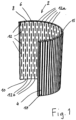
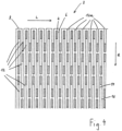
- the panel 2 of the sound absorption element according to the invention comprises a first panel surface 4 and a second panel surface 6 opposite the first panel surface, running in a plane parallel thereto and spaced by the thickness of the panel.
- the panel defines a longitudinal direction L and a transverse direction Q, as in 4 is shown.
- the plate also has two opposite plate side surfaces 8, 10 which run in a plane at right angles to the plate surfaces 4, 6.
- the plate 2 has sound absorption gaps 12 running in the transverse direction. These are continuous in the direction of thickness D (see e.g figure 5 ) and not continuous in the transverse direction Q and are each delimited by two gap side faces 14, 16 spaced apart from one another.
- a first part 12a of the sound absorption gaps 12 extends from a first of the two side faces 8 of the panel and through the panel in the direction of thickness.
- a second part 12b of the sound absorption gaps 12 extends from the second of the two side surfaces 10 of the panel and through the panel in the thickness direction.
- two sound absorption gaps 12 following one another in the longitudinal direction L are offset in relation to one another in the transverse direction Q and arranged so as to overlap one another.
- every second of the sound absorption gaps 12 arranged one on top of the other in the longitudinal direction L is configured identically with regard to its extent and its arrangement in the transverse direction Q.
- the sound absorption gaps 12 are rectangular in shape, with their extent in the transverse direction Q decreasing continuously in the thickness direction D, so that the extent of the respective sound absorption gap 12 in the transverse direction Q is greater on the first panel surface 4 than on the second panel surface 6.
- the sound absorption gaps 12 are milled into the panel in such a way that they (only) form a continuous groove 17 from one panel side surface 8 to the other panel side surface 10 on one of the two panel surfaces 4 in a region 15 close to the surface.
- a panel is obtained, for example, when the milling to produce the sound absorption gaps takes place from only one side, in the figure from the side of the first panel surface 4 . It is conceivable, for example, that the milling takes place with a circular saw, with this sawing permanently into the material of the panel while it is being moved in the direction from one panel side surface 8 or 10 to the other panel side surface 10 or 8 .
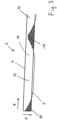
- FIG. 5 A corresponding sectional view is in figure 5 shown.
- material webs 18 are obtained which, in section, have approximately the shape of an isosceles and symmetrical trapezium, with the two diagonals being slightly concavely bent.
- corresponding material webs 18' are obtained which have a shape of a right-angled triangle with a concavely curved hypotenuse in section.
- the bending is due to the fact that when sawing, the inclination of the gap incision in the thickness direction D decreases continuously from the first panel surface 4 to the second panel surface 6 and increases continuously from the second panel surface 6 to the first panel surface 4.
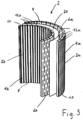
- the embodiment shown differs from that in FIG 1 shown on the one hand by a greater thickness of the panel 2.
- the sound absorption gaps 12 on both panel surfaces 4, 6 form a continuous groove 17 in a respective area 15 near the surface done on both sides; a corresponding sectional view with a material web 18′′ or 18′′′ approximately in the shape of a hexagon or an isosceles triangle is analogous to figure 5 in 6 shown.
- two plates according to 1 to be connected to one another as part panels 2a, 2b, the part panel surfaces 6a, 6b on which the sound absorption gaps 12 do not form a continuous groove being connected to one another.
- the plate thus obtained has one of the plate 2 corresponding external appearance, ie that the sound absorption gaps form a continuous groove on both panel surfaces 4a, 4b.
- a textile insert 20 - such as an acoustic fleece - is inserted between the partial panels 2a, 2b, as shown in 3 will be shown.
- the sound absorption obtained with the sound absorption element according to the invention is 7 shown measurement results of the reverberation time.
- the measurement on which the results are based was carried out according to the standard SN EN ISO 3382 "Acoustics - Measurements of room acoustics parameters - Part 2: Reverberation time in ordinary rooms (ISO 3382-2:2008)", using the precision method.
- the measurement was carried out in a room furnished according to normal use, with windows and doors closed.
- Table 1 The reverberation times measured for the respective octave bands are given in Table 1, the values obtained for a room equipped with the sound absorption elements according to the invention being compared with the values for a room without said elements (reference).
- Table 2 octave band 125Hz 250Hz 500Hz 1KHz 2KHz 4KHz with sound absorption element 1.90 1.95 1.95 1.77 1.62 1.29 reference 0.91 0.98 0.95 0.96 0.91 0.77 octave band 125Hz 250Hz 500Hz 1KHz 2KHz 4KHz with sound absorption element 2 1 1 1 1 1 reference 3 2 2 1 1 1 1 1
Landscapes
- Physics & Mathematics (AREA)
- Engineering & Computer Science (AREA)
- Acoustics & Sound (AREA)
- Multimedia (AREA)
- Building Environments (AREA)
- Transducers For Ultrasonic Waves (AREA)
Claims (14)
- Élément d'absorption acoustique comprenant une plaque (2) avec une première surface de plaque (4) qui est destinée à être tournée vers une source sonore et une deuxième surface de plaque (6) opposée à la première surface de plaque et espacée de l'épaisseur de la plaque, ainsi que deux surfaces latérales de plaque (8, 10) opposées l'une à l'autre, la plaque présentant des fentes d'absorption acoustique (12) s'étendant dans la direction transversale, qui sont continues dans la direction de l'épaisseur (D) et non continues dans la direction transversale (Q) et dont la largeur est respectivement limitée par deux surfaces latérales de fente (14, 16) espacées l'une de l'autre, et au moins deux fentes d'absorption acoustique (12) étant disposées l'une après l'autre dans la direction longitudinale (L), une première partie des fentes d'absorption acoustique (12a) part d'une première des deux surfaces latérales de plaque (8) et traverse celle-ci dans la direction de l'épaisseur (D), une deuxième partie des fentes d'absorption acoustique (12b) part de la deuxième des deux surfaces latérales de plaque (10) et traverse celle-ci dans la direction de l'épaisseur (D) et chaque fois deux fentes d'absorption acoustique (12) se succédant dans la direction longitudinale (L) sont disposées de manière décalée l'une par rapport à l'autre dans la direction transversale (Q) et se chevauchent l'une l'autre et, les fentes d'absorption acoustique (12) étant conçues de telle sorte que leur extension dans la direction transversale (Q) de la plaque (2) diminue de manière continue au moins par sections dans la direction de l'épaisseur (D), les fentes d'absorption acoustique (12) qui se succèdent dans la direction longitudinale (L) se chevauchant les unes les autres dans la direction transversale (Q) sur l'une des surfaces de plaque (4), sur l'autre surface de plaque (6), deux des fentes d'absorption acoustique (12) se succédant dans la direction longitudinale (L) se chevauchent également l'une l'autre dans la direction transversale (Q) ou leurs extrémités s'étendent à fleur l'une de l'autre.
- Élément d'absorption acoustique selon la revendication 1, caractérisé en ce que la plaque (2) est constituée d'un matériau comprenant du bois et/ou du plastique.
- Élément d'absorption acoustique selon la revendication 1 ou 2, caractérisé en ce que la plaque (2) est flexible.
- Élément d'absorption acoustique selon l'une des revendications précédentes, caractérisé en ce que les fentes d'absorption acoustique partant des surfaces latérales de plaque (8, 10) partent alternativement de surfaces latérales de plaque opposées dans la direction longitudinale (L).
- Élément d'absorption acoustique selon l'une des revendications précédentes, caractérisé en ce qu'une fente d'absorption acoustique (12) sur deux, disposées l'une sur l'autre dans la direction longitudinale (L), est conçue de manière identique en ce qui concerne son étendue et sa disposition dans la direction transversale (Q).
- Élément d'absorption acoustique selon l'une des revendications précédentes, caractérisé en ce que les fentes d'absorption acoustique (12) présentent une forme rectangulaire en coupe à travers un plan de coupe parallèle aux surfaces de plaque (4, 6).
- Élément d'absorption acoustique selon l'une des revendications précédentes, caractérisé en ce que, à l'état non plié de la plaque (2), les surfaces latérales de fente (14, 16) s'étendent dans des plans sensiblement parallèles entre eux.
- Élément d'absorption acoustique selon l'une des revendications précédentes, caractérisé en ce que, dans la direction transversale (Q), au moins deux des fentes d'absorption acoustique (12) sont situées sur une ligne droite.
- Élément d'absorption acoustique selon la revendication 8, caractérisé en ce que, parmi les fentes d'absorption acoustique (12) situées sur une ligne droite, au moins une ne part d'aucune des deux surfaces latérales de plaque (8, 10).
- Élément d'absorption acoustique selon l'une des revendications précédentes, caractérisé en ce qu'une fente d'absorption acoustique (12) ou au moins deux fentes d'absorption acoustique (12) situées sur une ligne droite forment dans une zone proche de la surface (15) une rainure (17) continue de l'une des surfaces latérales de plaque (8) à l'autre surface latérale de plaque (10).
- Élément d'absorption acoustique selon l'une des revendications précédentes, caractérisé en ce qu'il comprend en outre un support avec une base et un cadre entourant la base, par lequel la plaque est maintenue.
- Élément d'absorption acoustique selon la revendication 11, dans lequel la plaque est maintenue par le cadre sous une forme non plane.
- Procédé de fabrication d'un élément d'absorption acoustique selon l'une quelconque des revendications précédentes, caractérisé en ce que la plaque est obtenue à partir d'une structure en forme de plaque dans laquelle les fentes d'absorption sont formées par enlèvement de matière.
- Procédé selon la revendication 13, caractérisé en ce que l'enlèvement de matière est réalisé au moyen d'une scie circulaire, de préférence un groupe de scies circulaires à lames multiples.
Priority Applications (2)
| Application Number | Priority Date | Filing Date | Title |
|---|---|---|---|
| ES11007957T ES2952382T3 (es) | 2011-10-01 | 2011-10-01 | Elemento de absorción acústica |
| EP11007957.1A EP2575127B1 (fr) | 2011-10-01 | 2011-10-01 | Elément d'absorption acoustique |
Applications Claiming Priority (1)
| Application Number | Priority Date | Filing Date | Title |
|---|---|---|---|
| EP11007957.1A EP2575127B1 (fr) | 2011-10-01 | 2011-10-01 | Elément d'absorption acoustique |
Publications (3)
| Publication Number | Publication Date |
|---|---|
| EP2575127A1 EP2575127A1 (fr) | 2013-04-03 |
| EP2575127B1 true EP2575127B1 (fr) | 2023-06-07 |
| EP2575127C0 EP2575127C0 (fr) | 2023-06-07 |
Family
ID=44759365
Family Applications (1)
| Application Number | Title | Priority Date | Filing Date |
|---|---|---|---|
| EP11007957.1A Active EP2575127B1 (fr) | 2011-10-01 | 2011-10-01 | Elément d'absorption acoustique |
Country Status (2)
| Country | Link |
|---|---|
| EP (1) | EP2575127B1 (fr) |
| ES (1) | ES2952382T3 (fr) |
Families Citing this family (3)
| Publication number | Priority date | Publication date | Assignee | Title |
|---|---|---|---|---|
| CN105427852A (zh) * | 2014-09-04 | 2016-03-23 | 北京市劳动保护科学研究所 | 一种吸声板 |
| CH711582A1 (en) * | 2015-09-29 | 2017-03-31 | Akustik & Raum Ag | Sound-absorbing element. |
| US12209426B2 (en) | 2020-04-23 | 2025-01-28 | Spinneybeck Enterprises Inc. | Privacy enclosure |
Citations (2)
| Publication number | Priority date | Publication date | Assignee | Title |
|---|---|---|---|---|
| EP1138842A1 (fr) * | 2000-03-27 | 2001-10-04 | Mäger AG Innenausbau | Procédé de fabrication d'un élément insonorisant en forme de panneau et dispositif pour la mise en oeuvre du procédé |
| EP2020194A2 (fr) * | 2007-07-23 | 2009-02-04 | Serge Lunin | Composant plat |
Family Cites Families (8)
| Publication number | Priority date | Publication date | Assignee | Title |
|---|---|---|---|---|
| DE9116233U1 (de) * | 1991-04-10 | 1992-06-17 | VEGLA Vereinigte Glaswerke GmbH, 5100 Aachen | Schallabsorbierende Verglasung |
| US5560881A (en) | 1994-06-08 | 1996-10-01 | Usg Interiors, Inc. | Apparatus for producing a fissured, acoustical ceiling panel and method for manufacturing said apparatus |
| JP2003532127A (ja) * | 1999-05-06 | 2003-10-28 | ファイスト・オートモーティブ・ゲーエムベーハー・ウント・コンパニー・カーゲー | 防音要素、防音要素の使用及び防音要素の製造方法 |
| FR2823590B1 (fr) * | 2001-04-17 | 2003-07-25 | Eads Airbus Sa | Panneau d'attenuation acoustique comportant une couche resistive a composante structurale renforcee |
| DE10147645A1 (de) * | 2001-09-27 | 2003-04-10 | Faist Automotive Gmbh & Co Kg | Schallabschirmelement und Verfahren zur Herstellung |
| AT413406B (de) | 2003-08-18 | 2006-02-15 | Holzindustrie Leitinger Ges M | Schallabsorbierendes element |
| CH698026B1 (de) | 2004-02-18 | 2009-04-30 | Sevex Ag | Schallabsorbierendes Schlitzlochblech. |
| FR2908737B1 (fr) * | 2006-11-16 | 2009-12-04 | Airbus France | Revetement acoustique pour aeronef incorporant un systeme de traitement du givre par effet joule. |
-
2011
- 2011-10-01 EP EP11007957.1A patent/EP2575127B1/fr active Active
- 2011-10-01 ES ES11007957T patent/ES2952382T3/es active Active
Patent Citations (2)
| Publication number | Priority date | Publication date | Assignee | Title |
|---|---|---|---|---|
| EP1138842A1 (fr) * | 2000-03-27 | 2001-10-04 | Mäger AG Innenausbau | Procédé de fabrication d'un élément insonorisant en forme de panneau et dispositif pour la mise en oeuvre du procédé |
| EP2020194A2 (fr) * | 2007-07-23 | 2009-02-04 | Serge Lunin | Composant plat |
Non-Patent Citations (1)
| Title |
|---|
| DUKTA: "Dukta Flexible Wood", INSTAGRAM, 31 December 2009 (2009-12-31), XP055910771, Retrieved from the Internet <URL:https://www.instagram.com/p/Bmfmer4gXL4/> [retrieved on 20181126] * |
Also Published As
| Publication number | Publication date |
|---|---|
| ES2952382T3 (es) | 2023-10-31 |
| EP2575127A1 (fr) | 2013-04-03 |
| EP2575127C0 (fr) | 2023-06-07 |
Similar Documents
| Publication | Publication Date | Title |
|---|---|---|
| DE10347084B4 (de) | Abstimmbare, den Schall absorbierende, und die Luft filternde Dämpfungseinrichtung und Herstellungsverfahren | |
| EP2937483B1 (fr) | Panneau de construction, en particulier dalle de plafond ou murale | |
| EP1950357B1 (fr) | Eléments acoustiques | |
| CH647575A5 (de) | Schallabsorbierendes, nur aus mindestens zwei uebereinander angeordneten kunststoff-folien bestehendes bauelement. | |
| WO2000014353A1 (fr) | Element sous forme de plaque | |
| EP0388355A1 (fr) | Panneau absorbant les sons pour l'aménagement intérieur | |
| CH639453A5 (de) | Bauelement fuer die luftschalldaemmung. | |
| WO2000036240A1 (fr) | Corps moules structures pour l'absorption acoustique | |
| DE857271C (de) | Schallschluckende Verkleidungsplatte | |
| EP2579248A2 (fr) | Procédé de fabrication d'une plaque d'insonorisation à deux ou trois couches et plaque d'insonorisation associée | |
| AT413406B (de) | Schallabsorbierendes element | |
| DE29911495U1 (de) | Schallabsorbierende Platte für die Raumgestaltung | |
| EP2575127A1 (fr) | Elément d'absorption acoustique | |
| EP2963199B1 (fr) | Plaque isolante | |
| DE102022116863A1 (de) | Plattenförmiges Element für die Wand- und Deckenverkleidung | |
| EP3935624B1 (fr) | Absorbeur acoustique, structure et utilisation d'un absorbeur acoustique | |
| DE3513662A1 (de) | Schalldaempfeinrichtung | |
| DE20006946U1 (de) | Breitbandig schallabsorbierender Bauteil für Wände, Böden und Decken | |
| EP3246479B1 (fr) | Unité d'absorption de sons | |
| DE69409065T2 (de) | Schalldämmende Platte | |
| CH713133B1 (de) | Schallabsorbierendes Element. | |
| AT413121B (de) | Schalldämmendes paneel | |
| DE20112669U1 (de) | Schallabsorbierendes Paneel | |
| AT526400B1 (de) | Bauplatte | |
| DE102019118591A1 (de) | Schallabsorberanordnung |
Legal Events
| Date | Code | Title | Description |
|---|---|---|---|
| PUAI | Public reference made under article 153(3) epc to a published international application that has entered the european phase |
Free format text: ORIGINAL CODE: 0009012 |
|
| AK | Designated contracting states |
Kind code of ref document: A1 Designated state(s): AL AT BE BG CH CY CZ DE DK EE ES FI FR GB GR HR HU IE IS IT LI LT LU LV MC MK MT NL NO PL PT RO RS SE SI SK SM TR |
|
| AX | Request for extension of the european patent |
Extension state: BA ME |
|
| TPAC | Observations filed by third parties |
Free format text: ORIGINAL CODE: EPIDOSNTIPA |
|
| 17P | Request for examination filed |
Effective date: 20131002 |
|
| RBV | Designated contracting states (corrected) |
Designated state(s): AL AT BE BG CH CY CZ DE DK EE ES FI FR GB GR HR HU IE IS IT LI LT LU LV MC MK MT NL NO PL PT RO RS SE SI SK SM TR |
|
| RAP1 | Party data changed (applicant data changed or rights of an application transferred) |
Owner name: DUKTA GMBH |
|
| RIN1 | Information on inventor provided before grant (corrected) |
Inventor name: CHRISTIAN KUHN Inventor name: SERGE LUNIN |
|
| 17Q | First examination report despatched |
Effective date: 20151110 |
|
| GRAP | Despatch of communication of intention to grant a patent |
Free format text: ORIGINAL CODE: EPIDOSNIGR1 |
|
| STAA | Information on the status of an ep patent application or granted ep patent |
Free format text: STATUS: GRANT OF PATENT IS INTENDED |
|
| INTG | Intention to grant announced |
Effective date: 20180724 |
|
| TPAC | Observations filed by third parties |
Free format text: ORIGINAL CODE: EPIDOSNTIPA |
|
| GRAJ | Information related to disapproval of communication of intention to grant by the applicant or resumption of examination proceedings by the epo deleted |
Free format text: ORIGINAL CODE: EPIDOSDIGR1 |
|
| STAA | Information on the status of an ep patent application or granted ep patent |
Free format text: STATUS: EXAMINATION IS IN PROGRESS |
|
| INTC | Intention to grant announced (deleted) | ||
| GRAP | Despatch of communication of intention to grant a patent |
Free format text: ORIGINAL CODE: EPIDOSNIGR1 |
|
| STAA | Information on the status of an ep patent application or granted ep patent |
Free format text: STATUS: GRANT OF PATENT IS INTENDED |
|
| INTG | Intention to grant announced |
Effective date: 20221115 |
|
| TPAC | Observations filed by third parties |
Free format text: ORIGINAL CODE: EPIDOSNTIPA |
|
| GRAS | Grant fee paid |
Free format text: ORIGINAL CODE: EPIDOSNIGR3 |
|
| GRAA | (expected) grant |
Free format text: ORIGINAL CODE: 0009210 |
|
| STAA | Information on the status of an ep patent application or granted ep patent |
Free format text: STATUS: THE PATENT HAS BEEN GRANTED |
|
| AK | Designated contracting states |
Kind code of ref document: B1 Designated state(s): AL AT BE BG CH CY CZ DE DK EE ES FI FR GB GR HR HU IE IS IT LI LT LU LV MC MK MT NL NO PL PT RO RS SE SI SK SM TR |
|
| REG | Reference to a national code |
Ref country code: GB Ref legal event code: FG4D Free format text: NOT ENGLISH |
|
| REG | Reference to a national code |
Ref country code: CH Ref legal event code: EP Ref country code: AT Ref legal event code: REF Ref document number: 1577382 Country of ref document: AT Kind code of ref document: T Effective date: 20230615 |
|
| REG | Reference to a national code |
Ref country code: DE Ref legal event code: R096 Ref document number: 502011017424 Country of ref document: DE |
|
| U01 | Request for unitary effect filed |
Effective date: 20230705 |
|
| U07 | Unitary effect registered |
Designated state(s): AT BE BG DE DK EE FI FR IT LT LU LV MT NL PT SE SI Effective date: 20230807 |
|
| REG | Reference to a national code |
Ref country code: LT Ref legal event code: MG9D |
|
| PG25 | Lapsed in a contracting state [announced via postgrant information from national office to epo] |
Ref country code: NO Free format text: LAPSE BECAUSE OF FAILURE TO SUBMIT A TRANSLATION OF THE DESCRIPTION OR TO PAY THE FEE WITHIN THE PRESCRIBED TIME-LIMIT Effective date: 20230907 |
|
| REG | Reference to a national code |
Ref country code: ES Ref legal event code: FG2A Ref document number: 2952382 Country of ref document: ES Kind code of ref document: T3 Effective date: 20231031 |
|
| PG25 | Lapsed in a contracting state [announced via postgrant information from national office to epo] |
Ref country code: RS Free format text: LAPSE BECAUSE OF FAILURE TO SUBMIT A TRANSLATION OF THE DESCRIPTION OR TO PAY THE FEE WITHIN THE PRESCRIBED TIME-LIMIT Effective date: 20230607 Ref country code: HR Free format text: LAPSE BECAUSE OF FAILURE TO SUBMIT A TRANSLATION OF THE DESCRIPTION OR TO PAY THE FEE WITHIN THE PRESCRIBED TIME-LIMIT Effective date: 20230607 Ref country code: GR Free format text: LAPSE BECAUSE OF FAILURE TO SUBMIT A TRANSLATION OF THE DESCRIPTION OR TO PAY THE FEE WITHIN THE PRESCRIBED TIME-LIMIT Effective date: 20230908 |
|
| U20 | Renewal fee for the european patent with unitary effect paid |
Year of fee payment: 13 Effective date: 20231027 |
|
| PG25 | Lapsed in a contracting state [announced via postgrant information from national office to epo] |
Ref country code: SK Free format text: LAPSE BECAUSE OF FAILURE TO SUBMIT A TRANSLATION OF THE DESCRIPTION OR TO PAY THE FEE WITHIN THE PRESCRIBED TIME-LIMIT Effective date: 20230607 |
|
| PG25 | Lapsed in a contracting state [announced via postgrant information from national office to epo] |
Ref country code: IS Free format text: LAPSE BECAUSE OF FAILURE TO SUBMIT A TRANSLATION OF THE DESCRIPTION OR TO PAY THE FEE WITHIN THE PRESCRIBED TIME-LIMIT Effective date: 20231007 |
|
| PG25 | Lapsed in a contracting state [announced via postgrant information from national office to epo] |
Ref country code: SM Free format text: LAPSE BECAUSE OF FAILURE TO SUBMIT A TRANSLATION OF THE DESCRIPTION OR TO PAY THE FEE WITHIN THE PRESCRIBED TIME-LIMIT Effective date: 20230607 Ref country code: SK Free format text: LAPSE BECAUSE OF FAILURE TO SUBMIT A TRANSLATION OF THE DESCRIPTION OR TO PAY THE FEE WITHIN THE PRESCRIBED TIME-LIMIT Effective date: 20230607 Ref country code: RO Free format text: LAPSE BECAUSE OF FAILURE TO SUBMIT A TRANSLATION OF THE DESCRIPTION OR TO PAY THE FEE WITHIN THE PRESCRIBED TIME-LIMIT Effective date: 20230607 Ref country code: IS Free format text: LAPSE BECAUSE OF FAILURE TO SUBMIT A TRANSLATION OF THE DESCRIPTION OR TO PAY THE FEE WITHIN THE PRESCRIBED TIME-LIMIT Effective date: 20231007 Ref country code: CZ Free format text: LAPSE BECAUSE OF FAILURE TO SUBMIT A TRANSLATION OF THE DESCRIPTION OR TO PAY THE FEE WITHIN THE PRESCRIBED TIME-LIMIT Effective date: 20230607 |
|
| PG25 | Lapsed in a contracting state [announced via postgrant information from national office to epo] |
Ref country code: PL Free format text: LAPSE BECAUSE OF FAILURE TO SUBMIT A TRANSLATION OF THE DESCRIPTION OR TO PAY THE FEE WITHIN THE PRESCRIBED TIME-LIMIT Effective date: 20230607 |
|
| REG | Reference to a national code |
Ref country code: DE Ref legal event code: R097 Ref document number: 502011017424 Country of ref document: DE |
|
| PLBE | No opposition filed within time limit |
Free format text: ORIGINAL CODE: 0009261 |
|
| STAA | Information on the status of an ep patent application or granted ep patent |
Free format text: STATUS: NO OPPOSITION FILED WITHIN TIME LIMIT |
|
| 26N | No opposition filed |
Effective date: 20240308 |
|
| PG25 | Lapsed in a contracting state [announced via postgrant information from national office to epo] |
Ref country code: MC Free format text: LAPSE BECAUSE OF FAILURE TO SUBMIT A TRANSLATION OF THE DESCRIPTION OR TO PAY THE FEE WITHIN THE PRESCRIBED TIME-LIMIT Effective date: 20230607 |
|
| PG25 | Lapsed in a contracting state [announced via postgrant information from national office to epo] |
Ref country code: IE Free format text: LAPSE BECAUSE OF NON-PAYMENT OF DUE FEES Effective date: 20231001 |
|
| PG25 | Lapsed in a contracting state [announced via postgrant information from national office to epo] |
Ref country code: IE Free format text: LAPSE BECAUSE OF NON-PAYMENT OF DUE FEES Effective date: 20231001 |
|
| U20 | Renewal fee for the european patent with unitary effect paid |
Year of fee payment: 14 Effective date: 20241014 |
|
| PG25 | Lapsed in a contracting state [announced via postgrant information from national office to epo] |
Ref country code: CY Free format text: LAPSE BECAUSE OF FAILURE TO SUBMIT A TRANSLATION OF THE DESCRIPTION OR TO PAY THE FEE WITHIN THE PRESCRIBED TIME-LIMIT; INVALID AB INITIO Effective date: 20111001 |
|
| PG25 | Lapsed in a contracting state [announced via postgrant information from national office to epo] |
Ref country code: HU Free format text: LAPSE BECAUSE OF FAILURE TO SUBMIT A TRANSLATION OF THE DESCRIPTION OR TO PAY THE FEE WITHIN THE PRESCRIBED TIME-LIMIT; INVALID AB INITIO Effective date: 20111001 |
|
| REG | Reference to a national code |
Ref country code: CH Ref legal event code: U11 Free format text: ST27 STATUS EVENT CODE: U-0-0-U10-U11 (AS PROVIDED BY THE NATIONAL OFFICE) Effective date: 20251101 |
|
| U20 | Renewal fee for the european patent with unitary effect paid |
Year of fee payment: 15 Effective date: 20251008 |
|
| PG25 | Lapsed in a contracting state [announced via postgrant information from national office to epo] |
Ref country code: TR Free format text: LAPSE BECAUSE OF FAILURE TO SUBMIT A TRANSLATION OF THE DESCRIPTION OR TO PAY THE FEE WITHIN THE PRESCRIBED TIME-LIMIT Effective date: 20230607 |
|
| PGFP | Annual fee paid to national office [announced via postgrant information from national office to epo] |
Ref country code: GB Payment date: 20251022 Year of fee payment: 15 |
|
| PGFP | Annual fee paid to national office [announced via postgrant information from national office to epo] |
Ref country code: CH Payment date: 20251101 Year of fee payment: 15 |
|
| PGFP | Annual fee paid to national office [announced via postgrant information from national office to epo] |
Ref country code: ES Payment date: 20251210 Year of fee payment: 15 |