EP2575154B1 - Zelle zur Verteilung von Strom mittlerer Spannung - Google Patents
Zelle zur Verteilung von Strom mittlerer Spannung Download PDFInfo
- Publication number
- EP2575154B1 EP2575154B1 EP12306077.4A EP12306077A EP2575154B1 EP 2575154 B1 EP2575154 B1 EP 2575154B1 EP 12306077 A EP12306077 A EP 12306077A EP 2575154 B1 EP2575154 B1 EP 2575154B1
- Authority
- EP
- European Patent Office
- Prior art keywords
- cubicle
- current
- circuit
- electric distribution
- breaker
- Prior art date
- Legal status (The legal status is an assumption and is not a legal conclusion. Google has not performed a legal analysis and makes no representation as to the accuracy of the status listed.)
- Active
Links
Images

Classifications
-
- H—ELECTRICITY
- H01—ELECTRIC ELEMENTS
- H01H—ELECTRIC SWITCHES; RELAYS; SELECTORS; EMERGENCY PROTECTIVE DEVICES
- H01H33/00—High-tension or heavy-current switches with arc-extinguishing or arc-preventing means
- H01H33/60—Switches wherein the means for extinguishing or preventing the arc do not include separate means for obtaining or increasing flow of arc-extinguishing fluid
- H01H33/66—Vacuum switches
- H01H33/666—Operating arrangements
- H01H33/6661—Combination with other type of switch, e.g. for load break switches
-
- H—ELECTRICITY
- H01—ELECTRIC ELEMENTS
- H01H—ELECTRIC SWITCHES; RELAYS; SELECTORS; EMERGENCY PROTECTIVE DEVICES
- H01H31/00—Air-break switches for high tension without arc-extinguishing or arc-preventing means
- H01H31/02—Details
- H01H31/04—Interlocking mechanisms
- H01H31/10—Interlocking mechanisms for interlocking two or more switches
-
- H—ELECTRICITY
- H01—ELECTRIC ELEMENTS
- H01H—ELECTRIC SWITCHES; RELAYS; SELECTORS; EMERGENCY PROTECTIVE DEVICES
- H01H33/00—High-tension or heavy-current switches with arc-extinguishing or arc-preventing means
- H01H33/02—Details
- H01H33/04—Means for extinguishing or preventing arc between current-carrying parts
- H01H33/14—Multiple main contacts for the purpose of dividing the current through, or potential drop along, the arc
-
- H—ELECTRICITY
- H01—ELECTRIC ELEMENTS
- H01H—ELECTRIC SWITCHES; RELAYS; SELECTORS; EMERGENCY PROTECTIVE DEVICES
- H01H33/00—High-tension or heavy-current switches with arc-extinguishing or arc-preventing means
- H01H33/02—Details
- H01H33/04—Means for extinguishing or preventing arc between current-carrying parts
- H01H33/14—Multiple main contacts for the purpose of dividing the current through, or potential drop along, the arc
- H01H33/143—Multiple main contacts for the purpose of dividing the current through, or potential drop along, the arc of different construction or type
-
- H—ELECTRICITY
- H01—ELECTRIC ELEMENTS
- H01H—ELECTRIC SWITCHES; RELAYS; SELECTORS; EMERGENCY PROTECTIVE DEVICES
- H01H33/00—High-tension or heavy-current switches with arc-extinguishing or arc-preventing means
- H01H33/02—Details
- H01H33/04—Means for extinguishing or preventing arc between current-carrying parts
- H01H33/16—Impedances connected with contacts
-
- H—ELECTRICITY
- H01—ELECTRIC ELEMENTS
- H01H—ELECTRIC SWITCHES; RELAYS; SELECTORS; EMERGENCY PROTECTIVE DEVICES
- H01H9/00—Details of switching devices, not covered by groups H01H1/00 - H01H7/00
- H01H9/20—Interlocking, locking, or latching mechanisms
- H01H9/26—Interlocking, locking, or latching mechanisms for interlocking two or more switches
Definitions
- an electrical distribution cell of the kind mentioned above, as described in the patent application is known.
- FR 2 940 516 This cell comprises a switch or a circuit breaker also performing the disconnector function and, in series with this switch (or circuit breaker) a selector at least two positions respectively a current passage position and a grounding position.
- This cell is designed to conduct a current of 630 A and is therefore not able to conduct higher current levels, such as 1250 A.
- these cells that can withstand a higher nominal current than the mid-range generally correspond within a range with low consumption volumes, which means that the industrial costs of such an adaptation are not justified.
- the present invention solves these problems and proposes a simple and economical electrical distribution cell that can withstand a large nominal current without considerably increasing the necessary investments and the number of subsets made.
- the subject of the present invention is an electrical distribution cell according to claim 1.
- the first cell is adapted to conduct up to at least a first current value, while the second cell is sized to conduct at least the entire value of the nominal current minus the first current value mentioned above.
- the protection means of the first cell comprise a circuit breaker or a switch and the means of conduction and sectioning of the second cell comprise a disconnector or a switch at least two positions.
- the control mechanism of the circuit breaker controls the opening of the contacts of the disconnector, the contacts of the circuit breaker or the switch then opening with a certain delay, allowing the current to completely switch in the first branch before their separation, then the contacts of the circuit breaker open and remain open for the duration of the cut-off, during which the disconnector contacts continue to open, and during a closing maneuver, the contacts of the circuit breaker close first to establish the current in this so-called first cell, thus closing the protection circuit then, with a certain offset of time, the shut-off circuit being closed, the mechanism of the circuit breaker controls the closing of the contacts of the disconnector.
- the second cell comprises means for reducing the heating in said second cell.
- this cell comprises means for distributing the currents flowing respectively in the two cells.
- these means comprise means for increasing the impedance of the first cell.
- these means comprise a magnetic circuit placed in the first cell so as to increase its inductance.
- these means comprise, wound on the magnetic circuit, a winding closed on a resistor, an impedance or said winding itself, said magnetic circuit being placed around a shielded connecting conductor downstream of the two cells.
- these means comprise at least one pair comprising two balancing transformers respectively placed on two phases respectively belonging to the two cells, these two transformers each pair being electrically connected two by two by one of their secondary.
- connection interfaces to cables are electrically connected only to the so-called second cell, in order to increase the impedance on the so-called first cell.
- the lower link opposite the busbar, is designed so as to have a small section and / or have forms to increase its inductance, such as helical shapes.
- an inductance is added to a dedicated secondary protection current transformers of the so-called first cell so as to increase its impedance and thus limit its current to a small proportion of the nominal current to conduct.
- the mechanical control device of the disconnector is removed and in that it is directly controlled from the output shaft of the control device of the circuit breaker.
- control devices respectively of the circuit breaker and the disconnector are interlocked.
- the circuit breaker comprises a vacuum interrupter to perform the power failure.
- the mechanism of the circuit breaker controls both the moving contact of the bulb and the contacts of the disconnector.
- this cell comprises several so-called second cells equipped with disconnectors and making it possible to distribute a larger nominal current, the output shafts of which are mechanically connected to each other, the nominal current being distributed in these different cells.
- this cell comprises current balancing means, grouped two by two on pairs of neighboring cells.
- this cell is intended to conduct a current of 1250A, the first and second cells being sized to each conduct a current of 630A.
- the circuit breaker / switch is in vacuum breaking technology also performing the disconnector function.
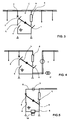
- a medium voltage electrical distribution cell C intended to electrically connect two busbars 1, 2 and to drive a high nominal current, for example in this particular embodiment, a current of 1250 A. , from "standard" cells of lower nominal currents.
- This cell C is intended to provide several functions, which are, respectively, to allow the passage of current between the busbars 1,2, to achieve an interruption of the current due to the cut made by a circuit breaker following the occurrence of a electrical fault in the circuit, which may occur for example during the protection of the network during a short circuit appeared in the latter, and to perform a sectioning of the circuit for independent operation of the two parts of the network.
- the first cell a has performance in cutoff and closure but does not allow to drive a high nominal current
- the second cell b is a cell for driving a high nominal current but has no power cutoff and closure.
- These two cells a, b are electrically connected in the upper part to a busbar of the upper table, and in the lower part to a lower busbar. These two cells a, b are electrically connected from a downstream side to a busbar of the board, and the other side said upstream to a coupling link located before the connections to the network cables.
- the upstream and downstream busbars will be adapted to conduct a permanent current of 1250A, or 630A depending on the location of this cell in the table and the balancing or distribution of currents referred to in each branch.
- the mechanism of the circuit breaker 3 of the first branch a, as well as the disconnector 6 of the second branch b are mechanically connected to operate according to a particular sequencing, as will be explained later.
- this cell C according to the invention is an arrival cell located at the end of the table.
- this cell C is arranged in the middle of the table. And on the figure 4 this cell is used to make a coupling and counting cell.
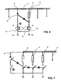
- the current carried by the downstream busbar 1 will be distributed in all branches.
- means are provided for distributing this current in such a way that the nominal current is higher in the second branch b, or the second branches b, c, d intended to conduct a current. nominal high.
- These means may be to increase the impedance in the first cell a having the circuit breaker 3 to reduce the nominal current therethrough and switch all this current or a large part thereof in the disconnector cell 6 which can easily perform this function of keep a high rated current.
- the circuit breaker 3 opens the contacts of the disconnector 6 by coupling the mechanism of the circuit breaker to the disconnector mechanism, the contacts of the bulb 13 opening with a certain delay.
- the opening of the contacts of the bulb realizes the opening of the cut-off circuit.
- the bulb remains open for the duration of the break, the recovery voltage being held across the disconnector 6 and the bulb 13.
- the two control mechanisms can be kept and interlocked.
- the mechanical connection between the two mechanisms allows a rapid maneuver of the switchgear of the switch of the second cell during the decompression of the closing springs of the circuit breaker bulb.
- the table thus produced is adapted to carry a current of 1250A, its busbar being dimensioned for 1250A and the lower or upper coupling bars being adapted to conduct a current of 1250A or a current of 630A, according to the configuration of the board.
- the disconnector must not interrupt or turn on the power because it does not have these two performances. It can just support a short arc for switching the current to be cut.
- the lower link opposite to the busbar, could be designed of small section and / or include forms increasing its inductance. For example helical shapes.
- Another solution could also be to add balancing current transformers on the two branches and cabled in opposition.
- circuit breaker cell with a very small section of copper, at least over a certain portion of its circuit, the isolating cell being sized to hold the permanent current and its section to be calculated so as to hold the current short circuit during the current switching time (a few ms) on opening.
- the present invention therefore proposes to perform a combination of cells based on the paralleling of a cell, called the nominal current, intended to conduct the nominal current, and a so-called control-protection cell, intended to perform the control functions. and electrical protection.
- This nominal current cell will only see part of this rated current and will never have to cut or establish it.
- the "control-protection” cell will see only a part of the nominal current, but above all will have to cut and establish all types of current.
- the so-called “nominal current” cell includes a disconnector while the cell called “protection -command” has a circuit breaker. It is the control mechanism of the circuit breaker that operates in direct contact with the circuit breaker contacts and at the same time the contacts of the disconnector.
- the location of the vacuum interrupter will receive a shielded over-molded conductor including at these ends the connection interfaces (busbar side and disconnect side). This replacement of the bulb reduces the heating of this cell, which will pass a higher current by increasing the impedance of the first cell relative to the second.
- the invention therefore makes it possible to considerably increase the value of the nominal current that a cell can conduct from existing cells or existing subsets.
- the nominal current be chosen by suitably dimensioning the isolator of the second cell, but the value of this current may also be modified by multiplying the number of so-called second cells in parallel with the so-called first cell.
- the cell created according to the invention is modular, the value of the nominal current can be adapted to the demand by adding modules for sectioning and passage of the nominal current, which will be connected in parallel with the other cells.
- the present invention therefore extends to any device putting in parallel a circuit breaker cell and a disconnector cell, this disconnector being sized to adapt to the various nominal currents that it is necessary to drive.
- the connection inserts can for example be sized to adapt to the maximum current to be distributed, and the disconnecting knives, modular design, can be duplicated as needed.
- the electrical protection device may be a circuit breaker or a switch with or without a vacuum bulb.
Landscapes
- Gas-Insulated Switchgears (AREA)
- Emergency Protection Circuit Devices (AREA)
- Driving Mechanisms And Operating Circuits Of Arc-Extinguishing High-Tension Switches (AREA)
- Distribution Board (AREA)
- Patch Boards (AREA)
Claims (21)
- Modulare Mittelspannungs-Verteilerschaltzelle zur Installation zwischen zwei Abschnitten eines elektrischen Leitungsnetzes, um mindestens die Funktion der Stromführung zwischen den beiden Netzabschnitten sowie der Stromabschaltung im Fehlerfall zu gewährleisten,
dadurch gekennzeichnet, dass sie eine erste Schaltzelle (a) zum Ausschalten und Einschalten des Stroms, welche Zelle elektrische Schutzmittel (3) mit einem angepassten Ausschalt- und Einschaltvermögen umfasst, sowie eine zweite Schaltzelle (b) die parallel zu der ersten Schaltzelle (a) zur Nennstromführung umfasst, welche Zelle Mittel (6) zur Führung des Nennstroms und zur Führung des Kurzschlussstroms vor dessen Abschaltung durch die genannten Schutzmittel (3) sowie Mittel zur Trennung des Leitungsabschnitts umfasst, wobei die genannte zweite Schaltzelle (b) zur Führung hoher Nennströme ausgelegt ist, der genannte Trennschalter (6) über die genannten elektrischen Schutzmittel (3) angesteuert wird und der Wert des Nennstroms durch Hinzufügung weiterer, parallel zu den vorhandenen Schaltzellen geschalteten Trennungs- und Nennstrom-Führungsmodulen an die Installationsbedürfnisse angepasst werden kann. - Verteilerschaltzelle nach Anspruch 1, dadurch gekennzeichnet, dass die erste Schaltzelle (a) Mittel zur Führung mindestens eines ersten Stromwerts umfasst, während die zweite Schaltzelle (b) Mittel zur Führung mindestens des gesamten Nennstroms, vermindert um den genannten ersten Stromwert umfasst.
- Verteilerschaltzelle nach Anspruch 1 oder 2, dadurch gekennzeichnet, dass die Schutzmittel (3) der ersten Schaltzelle (a) einen Leistungsschalter oder Lastschalter umfassen und die Stromführungs- und Trennungsmittel (6) der zweiten Schaltzelle (b) einen Trennschalter (6) oder einen Schalter mit mindestens zwei Stellungen umfasst.
- Verteilerschaltzelle nach Anspruch 3, dadurch gekennzeichnet, dass der Schaltmechanismus des Leistungsschalters mechanisch mit den Kontakten des Trennschalters verbunden ist, derart, dass bei einer Ausschalthandlung der Schaltmechanismus des Leistungsschalters (3) das Öffnen der Kontakte des Trennschalters (6) steuert, wobei die Kontakte des Leistungsschalters (3) bzw. Lastschalters erst mit einer bestimmten Zeitverzögerung abschalten, so dass der Strom vor Abschaltung dieser Kontakte vollständig auf den ersten Zweig (a) umgeschaltet werden kann und die Kontakte des Leistungsschalters (3) anschließend abschalten und über die gesamte Dauer der Ausschalthandlung, in deren Verlauf sich die Kontakte des Trennschalters (6) weiter öffnen, abgeschaltet bleiben, und dass bei einer Einschalthandlung die Kontakte des Leistungsschalters (3) zuerst eingeschaltet werden, wodurch der Stromfluss in dieser als erste Zelle bezeichneten Schaltzelle (a) ermöglicht und der Schutzstromkreis geschlossen wird, und der Schaltmechanismus des Leistungsschalters (3) bei bereits eingeschaltetem Ausschalt-Einschaltkreis nach Ablauf einer bestimmten Zeitverzögerung das Schließen der Kontakte des Trennschalters (6) steuert.
- Verteilerschaltzelle nach Anspruch 3 oder 4, dadurch gekennzeichnet, dass die zweite Schaltzelle (b) Mittel zur Reduzierung der Erwärmung in der genannten zweiten Schaltzelle umfasst.
- Verteilerschaltzelle nach irgendeinem der vorhergehenden Ansprüche, dadurch gekennzeichnet, dass sie Mittel zur Aufteilung des Stroms auf die beiden Schaltzellen (a, b) umfasst.
- Verteilerschaltzelle nach Anspruch 6, dadurch gekennzeichnet, dass diese Mittel ihrerseits Mittel zur Erhöhung der Impedanz der ersten Schaltzelle (a) umfassen.
- Verteilerschaltzelle nach Anspruch 7, dadurch gekennzeichnet, dass diese Mittel einen in der ersten Schaltzelle (a) installierten Magnetkreis (7) umfassen, der dazu dient, den induktiven Widerstand der Schaltzelle zu erhöhen.
- Verteilerschaltzelle nach Anspruch 7 oder 8, dadurch gekennzeichnet, dass diese Mittel eine um den Magnetkreis geführte, über einen Widerstand (10), eine Impedanz oder in sich selbst geschlossene Wicklung (9) umfasst, wobei der genannte Magnetkreis um einen geschirmten Verbindungsleiter zur abgangsseitigen Verbindung der beiden Schaltzellen geführt ist.
- Verteilerschaltzelle nach Anspruch 6, dadurch gekennzeichnet, dass diese Mittel mindestens eine Zwillingsschaltung aus zwei Ausgleichs-Stromwandlern (11, 12) umfassen, die in zwei entsprechende Phasen der zwei Schaltzellen (a, b) geschaltet sind, wobei die beiden genannten Ausgleichs-Stromwandler jeder Zwillingsschaltung paarweise über eine ihrer Sekundärwicklungen miteinander verbunden sind.
- Verteilerschaltzelle nach Anspruch 7, dadurch gekennzeichnet, dass die Verbindungsvorrichtungen für den Kabelanschluss nur mit der sogenannten zweiten Schaltzelle (b) elektrisch verbunden sind, um die Impedanz der sogenannten ersten Schaltzelle zu erhöhen.
- Verteilerschaltzelle nach Anspruch 7, dadurch gekennzeichnet, dass eine dafür vorgesehene Sekundärwicklung der Schutz-Stromwandler der sogenannten ersten Schaltzelle mit einem zusätzlichen induktiven Widerstand beschaltet ist, um die Impedanz dieser Schaltzelle zu erhöhen und so deren Strom auf einen Bruchteil des zu führenden Nennstroms zu begrenzen.
- Verteilerschaltzelle nach irgendeinem der Ansprüche 3 bis 12, dadurch gekennzeichnet, dass die Vorrichtung zur mechanischen Betätigung des Trennschalters (6) entfällt und der Trennschalter direkt über die Ausgangswelle des Schaltmechanismus' des Leistungsschalters (3) angesteuert wird.
- Verteilerschaltzelle nach irgendeinem der Ansprüche 3 bis 13, dadurch gekennzeichnet, dass die Schaltmechanismen des Leistungsschalters (3) und des Trennschalters (6) gegenseitig verriegelt sind.
- Verteilerschaltzelle nach irgendeinem der Ansprüche 3 bis 14, dadurch gekennzeichnet, dass der Leistungsschalter eine Vakuum-Schaltröhre zur Stromabschaltung umfasst.
- Verteilerschaltzelle nach Anspruch 15, dadurch gekennzeichnet, dass der Schaltmechanismus des Leistungsschalters (3) sowohl den beweglichen Kontakt der Vakuumschaltröhre (13) als auch die Kontakte des Trennschalters (6) ansteuert.
- Verteilerschaltzelle nach irgendeinem der vorhergehenden Ansprüche, dadurch gekennzeichnet, dass sie mehrere, sogenannte zweite Schaltzellen (c, d, e) mit Trennschaltern umfasst, welche die Verteilung eines höheren Nennstroms erlauben und deren Ausgangswellen mechanisch miteinander verbunden sind, wobei der Nennstrom auf diese einzelnen Schaltzellen aufgeteilt wird.
- Verteilerschaltzelle nach Anspruch 17, dadurch gekennzeichnet, dass sie paarweise in jeweils zwei benachbarte Schaltzellen geschaltete Strom-Ausgleichsmittel umfasst.
- Verteilerschaltzelle nach irgendeinem der vorhergehenden Ansprüche, dadurch gekennzeichnet, dass die Schaltzelle als an einem Ende der Schaltanlage installierte Eingangs-Schaltzelle, als in der Mitte der Schaltanlage installierte Eingangs-Schaltzelle, als Koppel-Schaltzelle oder als Zähler-Schaltzelle ausgebildet ist.
- Verteilerschaltzelle nach irgendeinem der vorhergehenden Ansprüche, dadurch gekennzeichnet, dass diese Schaltzelle C dazu dient, einen Strom von 1250 A zu führen, und die erste Schaltzelle (a) sowie die zweite Schaltzelle (b) so ausgelegt sind, dass sie jeweils 630 A führen.
- Verteilerschaltzelle nach irgendeinem der Ansprüche 3 bis 20, dadurch gekennzeichnet, dass der Leistungsschalter/Lastschalter (3) in Vakuum-Schalttechnik ausgeführt ist und zusätzlich eine Trennschalterfunktion (6) umfasst.
Applications Claiming Priority (1)
| Application Number | Priority Date | Filing Date | Title |
|---|---|---|---|
| FR1102931A FR2980634B1 (fr) | 2011-09-27 | 2011-09-27 | Cellule de distribution electrique moyenne tension |
Publications (2)
| Publication Number | Publication Date |
|---|---|
| EP2575154A1 EP2575154A1 (de) | 2013-04-03 |
| EP2575154B1 true EP2575154B1 (de) | 2015-07-29 |
Family
ID=46800147
Family Applications (1)
| Application Number | Title | Priority Date | Filing Date |
|---|---|---|---|
| EP12306077.4A Active EP2575154B1 (de) | 2011-09-27 | 2012-09-07 | Zelle zur Verteilung von Strom mittlerer Spannung |
Country Status (4)
| Country | Link |
|---|---|
| EP (1) | EP2575154B1 (de) |
| CN (1) | CN103022908B (de) |
| ES (1) | ES2547343T3 (de) |
| FR (1) | FR2980634B1 (de) |
Families Citing this family (1)
| Publication number | Priority date | Publication date | Assignee | Title |
|---|---|---|---|---|
| FR3021159B1 (fr) * | 2014-05-15 | 2016-05-06 | Schneider Electric Ind Sas | Appareillage de coupure electrique moyenne tension utilisant la technique de coupure dans le vide |
Family Cites Families (6)
| Publication number | Priority date | Publication date | Assignee | Title |
|---|---|---|---|---|
| DE3642108A1 (de) * | 1986-12-10 | 1988-06-16 | Bbc Brown Boveri & Cie | Schaltanlage zur verteilung elektrischer energie und verfahren zum betreiben der schaltanlage |
| WO1999052120A1 (de) * | 1998-04-08 | 1999-10-14 | Siemens Aktiengesellschaft | Hochstromschalter, insbesondere generator-leistungsschalter |
| JP3799924B2 (ja) * | 2000-01-11 | 2006-07-19 | 株式会社日立製作所 | 電力用遮断器および発電所電気回路装置 |
| JP4162664B2 (ja) * | 2005-02-22 | 2008-10-08 | 株式会社日立製作所 | 真空スイッチギヤ |
| FR2940516B1 (fr) | 2008-12-18 | 2012-09-28 | Schneider Electric Ind Sas | Cellule de distribution electrique moyenne tension |
| CN101908435B (zh) * | 2010-08-05 | 2012-12-19 | 西安通大思源电器有限公司 | 一种永磁操动的真空断路器 |
-
2011
- 2011-09-27 FR FR1102931A patent/FR2980634B1/fr not_active Expired - Fee Related
-
2012
- 2012-09-07 ES ES12306077.4T patent/ES2547343T3/es active Active
- 2012-09-07 EP EP12306077.4A patent/EP2575154B1/de active Active
- 2012-09-26 CN CN201210363795.3A patent/CN103022908B/zh active Active
Also Published As
| Publication number | Publication date |
|---|---|
| FR2980634A1 (fr) | 2013-03-29 |
| FR2980634B1 (fr) | 2013-09-06 |
| EP2575154A1 (de) | 2013-04-03 |
| CN103022908B (zh) | 2017-05-31 |
| ES2547343T3 (es) | 2015-10-05 |
| CN103022908A (zh) | 2013-04-03 |
Similar Documents
| Publication | Publication Date | Title |
|---|---|---|
| EP2359378B1 (de) | Elektrische mittelspannungs-verteilerzelle | |
| EP1974362B1 (de) | Generator-isolator mit integriertem widerstand | |
| EP1974363B1 (de) | Schalter zum abschalten eines generator-schutzschalters einer kompaktstruktur | |
| EP1870916B1 (de) | Betätigung eines Lasttrennschalters durch Kulissenzylinder | |
| EP1855300B1 (de) | Trennschalter für einen Wechselstromschalter, der von einem Servomotor betätigt wird | |
| EP3577672A1 (de) | Hochspannungs-gleichstromsperre | |
| EP0096601A1 (de) | Funktioneller Niederspannungs-Energieverteilungsblock | |
| FR3072826B1 (fr) | Appareil de coupure electrique, procede et installation utilisant un tel appareil | |
| EP1107269B1 (de) | Drehstromschaltgerät mit kompensiertem Magnetkreis, insbesondere für Starkstrom mit zwei Polen pro Phase | |
| EP2575154A1 (de) | Zelle zur Verteilung von Strom mittlerer Spannung | |
| CA2912175C (fr) | Organe hybride de coupure pour circuit electrique | |
| EP4193376A2 (de) | Stromunterbrechungsvorrichtung für elektrischen hochspannungsstrom, anlage mit einer solchen vorrichtung, steuerverfahren und verfahren zur bewertung der integrität eines elektrischen leiters | |
| FR2849968A1 (fr) | Centre de transformation pour transformateur autoprotege | |
| FR2897208A1 (fr) | Tableau electrique. | |
| EP4104195B1 (de) | Mechanische stromabschaltvorrichtung für hochspannungsgleichstrom mit einem kondensator in einer sekundären bahn, einrichtung und verfahren mit einer solchen vorrichtung | |
| EP2945176B1 (de) | Mittelspannungsschaltanlage mit Vakuumschaltsstechnik | |
| EP2200060B1 (de) | Zelle zur Verteilung von Strom mittlerer Spannung | |
| FR2823002A1 (fr) | Interrupteur/sectionneur multifonctionnel pour poste de distribution electrique | |
| EP2682970B1 (de) | Schaltgerät mit Mitteln zum geschlossenhalten elektrischer Kontakte | |
| EP2743957B1 (de) | Gerät zur Stromunterbrechung, insbesondere Anschluss-Überlastschalter | |
| FR3075458A1 (fr) | Appareil electrique destine a etablir ou interrompre le courant dans un circuit electrique | |
| CH338239A (fr) | Poste de commutation et de coupure d'un réseau de transport et de distribution d'énergie électrique polyphasée | |
| EP3070727A1 (de) | Trennvorrichtung zur hochspannungsstrom-unterbrechung oder -verbindung | |
| FR2944644A1 (fr) | Appareil electrique interrupteur et appareillage electrique d'interruption. | |
| FR2954621A1 (fr) | Dispositif d'inversion de phases a pinces |
Legal Events
| Date | Code | Title | Description |
|---|---|---|---|
| PUAI | Public reference made under article 153(3) epc to a published international application that has entered the european phase |
Free format text: ORIGINAL CODE: 0009012 |
|
| AK | Designated contracting states |
Kind code of ref document: A1 Designated state(s): AL AT BE BG CH CY CZ DE DK EE ES FI FR GB GR HR HU IE IS IT LI LT LU LV MC MK MT NL NO PL PT RO RS SE SI SK SM TR |
|
| AX | Request for extension of the european patent |
Extension state: BA ME |
|
| 17P | Request for examination filed |
Effective date: 20130419 |
|
| GRAP | Despatch of communication of intention to grant a patent |
Free format text: ORIGINAL CODE: EPIDOSNIGR1 |
|
| RIC1 | Information provided on ipc code assigned before grant |
Ipc: H01H 33/666 20060101AFI20150407BHEP |
|
| INTG | Intention to grant announced |
Effective date: 20150421 |
|
| RIN1 | Information on inventor provided before grant (corrected) |
Inventor name: KERSUSAN, JEAN-PIERRE Inventor name: PREVE, CHRISTOPHE |
|
| GRAS | Grant fee paid |
Free format text: ORIGINAL CODE: EPIDOSNIGR3 |
|
| GRAA | (expected) grant |
Free format text: ORIGINAL CODE: 0009210 |
|
| REG | Reference to a national code |
Ref country code: FR Ref legal event code: PLFP Year of fee payment: 4 |
|
| AK | Designated contracting states |
Kind code of ref document: B1 Designated state(s): AL AT BE BG CH CY CZ DE DK EE ES FI FR GB GR HR HU IE IS IT LI LT LU LV MC MK MT NL NO PL PT RO RS SE SI SK SM TR |
|
| REG | Reference to a national code |
Ref country code: GB Ref legal event code: FG4D Free format text: NOT ENGLISH |
|
| REG | Reference to a national code |
Ref country code: CH Ref legal event code: EP |
|
| REG | Reference to a national code |
Ref country code: AT Ref legal event code: REF Ref document number: 739870 Country of ref document: AT Kind code of ref document: T Effective date: 20150815 |
|
| REG | Reference to a national code |
Ref country code: IE Ref legal event code: FG4D Free format text: LANGUAGE OF EP DOCUMENT: FRENCH |
|
| REG | Reference to a national code |
Ref country code: DE Ref legal event code: R096 Ref document number: 602012009112 Country of ref document: DE |
|
| REG | Reference to a national code |
Ref country code: ES Ref legal event code: FG2A Ref document number: 2547343 Country of ref document: ES Kind code of ref document: T3 Effective date: 20151005 |
|
| REG | Reference to a national code |
Ref country code: AT Ref legal event code: MK05 Ref document number: 739870 Country of ref document: AT Kind code of ref document: T Effective date: 20150729 |
|
| REG | Reference to a national code |
Ref country code: LT Ref legal event code: MG4D |
|
| REG | Reference to a national code |
Ref country code: NL Ref legal event code: MP Effective date: 20150729 |
|
| PG25 | Lapsed in a contracting state [announced via postgrant information from national office to epo] |
Ref country code: FI Free format text: LAPSE BECAUSE OF FAILURE TO SUBMIT A TRANSLATION OF THE DESCRIPTION OR TO PAY THE FEE WITHIN THE PRESCRIBED TIME-LIMIT Effective date: 20150729 Ref country code: GR Free format text: LAPSE BECAUSE OF FAILURE TO SUBMIT A TRANSLATION OF THE DESCRIPTION OR TO PAY THE FEE WITHIN THE PRESCRIBED TIME-LIMIT Effective date: 20151030 Ref country code: LT Free format text: LAPSE BECAUSE OF FAILURE TO SUBMIT A TRANSLATION OF THE DESCRIPTION OR TO PAY THE FEE WITHIN THE PRESCRIBED TIME-LIMIT Effective date: 20150729 Ref country code: LV Free format text: LAPSE BECAUSE OF FAILURE TO SUBMIT A TRANSLATION OF THE DESCRIPTION OR TO PAY THE FEE WITHIN THE PRESCRIBED TIME-LIMIT Effective date: 20150729 Ref country code: NO Free format text: LAPSE BECAUSE OF FAILURE TO SUBMIT A TRANSLATION OF THE DESCRIPTION OR TO PAY THE FEE WITHIN THE PRESCRIBED TIME-LIMIT Effective date: 20151029 |
|
| PG25 | Lapsed in a contracting state [announced via postgrant information from national office to epo] |
Ref country code: RS Free format text: LAPSE BECAUSE OF FAILURE TO SUBMIT A TRANSLATION OF THE DESCRIPTION OR TO PAY THE FEE WITHIN THE PRESCRIBED TIME-LIMIT Effective date: 20150729 Ref country code: PT Free format text: LAPSE BECAUSE OF FAILURE TO SUBMIT A TRANSLATION OF THE DESCRIPTION OR TO PAY THE FEE WITHIN THE PRESCRIBED TIME-LIMIT Effective date: 20151130 Ref country code: AT Free format text: LAPSE BECAUSE OF FAILURE TO SUBMIT A TRANSLATION OF THE DESCRIPTION OR TO PAY THE FEE WITHIN THE PRESCRIBED TIME-LIMIT Effective date: 20150729 Ref country code: PL Free format text: LAPSE BECAUSE OF FAILURE TO SUBMIT A TRANSLATION OF THE DESCRIPTION OR TO PAY THE FEE WITHIN THE PRESCRIBED TIME-LIMIT Effective date: 20150729 Ref country code: HR Free format text: LAPSE BECAUSE OF FAILURE TO SUBMIT A TRANSLATION OF THE DESCRIPTION OR TO PAY THE FEE WITHIN THE PRESCRIBED TIME-LIMIT Effective date: 20150729 Ref country code: IS Free format text: LAPSE BECAUSE OF FAILURE TO SUBMIT A TRANSLATION OF THE DESCRIPTION OR TO PAY THE FEE WITHIN THE PRESCRIBED TIME-LIMIT Effective date: 20151129 Ref country code: SE Free format text: LAPSE BECAUSE OF FAILURE TO SUBMIT A TRANSLATION OF THE DESCRIPTION OR TO PAY THE FEE WITHIN THE PRESCRIBED TIME-LIMIT Effective date: 20150729 |
|
| PG25 | Lapsed in a contracting state [announced via postgrant information from national office to epo] |
Ref country code: NL Free format text: LAPSE BECAUSE OF FAILURE TO SUBMIT A TRANSLATION OF THE DESCRIPTION OR TO PAY THE FEE WITHIN THE PRESCRIBED TIME-LIMIT Effective date: 20150729 |
|
| PG25 | Lapsed in a contracting state [announced via postgrant information from national office to epo] |
Ref country code: CZ Free format text: LAPSE BECAUSE OF FAILURE TO SUBMIT A TRANSLATION OF THE DESCRIPTION OR TO PAY THE FEE WITHIN THE PRESCRIBED TIME-LIMIT Effective date: 20150729 Ref country code: SK Free format text: LAPSE BECAUSE OF FAILURE TO SUBMIT A TRANSLATION OF THE DESCRIPTION OR TO PAY THE FEE WITHIN THE PRESCRIBED TIME-LIMIT Effective date: 20150729 Ref country code: MC Free format text: LAPSE BECAUSE OF FAILURE TO SUBMIT A TRANSLATION OF THE DESCRIPTION OR TO PAY THE FEE WITHIN THE PRESCRIBED TIME-LIMIT Effective date: 20150729 Ref country code: DK Free format text: LAPSE BECAUSE OF FAILURE TO SUBMIT A TRANSLATION OF THE DESCRIPTION OR TO PAY THE FEE WITHIN THE PRESCRIBED TIME-LIMIT Effective date: 20150729 Ref country code: LU Free format text: LAPSE BECAUSE OF FAILURE TO SUBMIT A TRANSLATION OF THE DESCRIPTION OR TO PAY THE FEE WITHIN THE PRESCRIBED TIME-LIMIT Effective date: 20150907 Ref country code: EE Free format text: LAPSE BECAUSE OF FAILURE TO SUBMIT A TRANSLATION OF THE DESCRIPTION OR TO PAY THE FEE WITHIN THE PRESCRIBED TIME-LIMIT Effective date: 20150729 |
|
| REG | Reference to a national code |
Ref country code: CH Ref legal event code: PL |
|
| REG | Reference to a national code |
Ref country code: DE Ref legal event code: R097 Ref document number: 602012009112 Country of ref document: DE |
|
| PG25 | Lapsed in a contracting state [announced via postgrant information from national office to epo] |
Ref country code: RO Free format text: LAPSE BECAUSE OF FAILURE TO SUBMIT A TRANSLATION OF THE DESCRIPTION OR TO PAY THE FEE WITHIN THE PRESCRIBED TIME-LIMIT Effective date: 20150729 |
|
| PLBE | No opposition filed within time limit |
Free format text: ORIGINAL CODE: 0009261 |
|
| STAA | Information on the status of an ep patent application or granted ep patent |
Free format text: STATUS: NO OPPOSITION FILED WITHIN TIME LIMIT |
|
| REG | Reference to a national code |
Ref country code: IE Ref legal event code: MM4A |
|
| REG | Reference to a national code |
Ref country code: FR Ref legal event code: PLFP Year of fee payment: 5 |
|
| 26N | No opposition filed |
Effective date: 20160502 |
|
| PG25 | Lapsed in a contracting state [announced via postgrant information from national office to epo] |
Ref country code: LI Free format text: LAPSE BECAUSE OF NON-PAYMENT OF DUE FEES Effective date: 20150930 Ref country code: CH Free format text: LAPSE BECAUSE OF NON-PAYMENT OF DUE FEES Effective date: 20150930 Ref country code: IE Free format text: LAPSE BECAUSE OF NON-PAYMENT OF DUE FEES Effective date: 20150907 |
|
| PG25 | Lapsed in a contracting state [announced via postgrant information from national office to epo] |
Ref country code: SI Free format text: LAPSE BECAUSE OF FAILURE TO SUBMIT A TRANSLATION OF THE DESCRIPTION OR TO PAY THE FEE WITHIN THE PRESCRIBED TIME-LIMIT Effective date: 20150729 |
|
| PG25 | Lapsed in a contracting state [announced via postgrant information from national office to epo] |
Ref country code: MT Free format text: LAPSE BECAUSE OF FAILURE TO SUBMIT A TRANSLATION OF THE DESCRIPTION OR TO PAY THE FEE WITHIN THE PRESCRIBED TIME-LIMIT Effective date: 20150729 |
|
| PG25 | Lapsed in a contracting state [announced via postgrant information from national office to epo] |
Ref country code: SM Free format text: LAPSE BECAUSE OF FAILURE TO SUBMIT A TRANSLATION OF THE DESCRIPTION OR TO PAY THE FEE WITHIN THE PRESCRIBED TIME-LIMIT Effective date: 20150729 Ref country code: BG Free format text: LAPSE BECAUSE OF FAILURE TO SUBMIT A TRANSLATION OF THE DESCRIPTION OR TO PAY THE FEE WITHIN THE PRESCRIBED TIME-LIMIT Effective date: 20150729 Ref country code: HU Free format text: LAPSE BECAUSE OF FAILURE TO SUBMIT A TRANSLATION OF THE DESCRIPTION OR TO PAY THE FEE WITHIN THE PRESCRIBED TIME-LIMIT; INVALID AB INITIO Effective date: 20120907 |
|
| PG25 | Lapsed in a contracting state [announced via postgrant information from national office to epo] |
Ref country code: CY Free format text: LAPSE BECAUSE OF FAILURE TO SUBMIT A TRANSLATION OF THE DESCRIPTION OR TO PAY THE FEE WITHIN THE PRESCRIBED TIME-LIMIT Effective date: 20150729 |
|
| PG25 | Lapsed in a contracting state [announced via postgrant information from national office to epo] |
Ref country code: BE Free format text: LAPSE BECAUSE OF NON-PAYMENT OF DUE FEES Effective date: 20150930 |
|
| PG25 | Lapsed in a contracting state [announced via postgrant information from national office to epo] |
Ref country code: TR Free format text: LAPSE BECAUSE OF FAILURE TO SUBMIT A TRANSLATION OF THE DESCRIPTION OR TO PAY THE FEE WITHIN THE PRESCRIBED TIME-LIMIT Effective date: 20150729 |
|
| REG | Reference to a national code |
Ref country code: FR Ref legal event code: PLFP Year of fee payment: 6 |
|
| PG25 | Lapsed in a contracting state [announced via postgrant information from national office to epo] |
Ref country code: MK Free format text: LAPSE BECAUSE OF FAILURE TO SUBMIT A TRANSLATION OF THE DESCRIPTION OR TO PAY THE FEE WITHIN THE PRESCRIBED TIME-LIMIT Effective date: 20150729 |
|
| REG | Reference to a national code |
Ref country code: FR Ref legal event code: PLFP Year of fee payment: 7 |
|
| PG25 | Lapsed in a contracting state [announced via postgrant information from national office to epo] |
Ref country code: AL Free format text: LAPSE BECAUSE OF FAILURE TO SUBMIT A TRANSLATION OF THE DESCRIPTION OR TO PAY THE FEE WITHIN THE PRESCRIBED TIME-LIMIT Effective date: 20150729 |
|
| PGFP | Annual fee paid to national office [announced via postgrant information from national office to epo] |
Ref country code: GB Payment date: 20200925 Year of fee payment: 9 |
|
| PGFP | Annual fee paid to national office [announced via postgrant information from national office to epo] |
Ref country code: DE Payment date: 20201127 Year of fee payment: 9 Ref country code: ES Payment date: 20201020 Year of fee payment: 9 Ref country code: IT Payment date: 20200923 Year of fee payment: 9 |
|
| REG | Reference to a national code |
Ref country code: DE Ref legal event code: R119 Ref document number: 602012009112 Country of ref document: DE |
|
| GBPC | Gb: european patent ceased through non-payment of renewal fee |
Effective date: 20210907 |
|
| PG25 | Lapsed in a contracting state [announced via postgrant information from national office to epo] |
Ref country code: GB Free format text: LAPSE BECAUSE OF NON-PAYMENT OF DUE FEES Effective date: 20210907 Ref country code: DE Free format text: LAPSE BECAUSE OF NON-PAYMENT OF DUE FEES Effective date: 20220401 |
|
| PG25 | Lapsed in a contracting state [announced via postgrant information from national office to epo] |
Ref country code: IT Free format text: LAPSE BECAUSE OF NON-PAYMENT OF DUE FEES Effective date: 20210907 |
|
| REG | Reference to a national code |
Ref country code: ES Ref legal event code: FD2A Effective date: 20221104 |
|
| PG25 | Lapsed in a contracting state [announced via postgrant information from national office to epo] |
Ref country code: ES Free format text: LAPSE BECAUSE OF NON-PAYMENT OF DUE FEES Effective date: 20210908 |
|
| PGFP | Annual fee paid to national office [announced via postgrant information from national office to epo] |
Ref country code: FR Payment date: 20250925 Year of fee payment: 14 |