EP2575190A2 - Wiederaufladbare Batterie - Google Patents
Wiederaufladbare Batterie Download PDFInfo
- Publication number
- EP2575190A2 EP2575190A2 EP12178842A EP12178842A EP2575190A2 EP 2575190 A2 EP2575190 A2 EP 2575190A2 EP 12178842 A EP12178842 A EP 12178842A EP 12178842 A EP12178842 A EP 12178842A EP 2575190 A2 EP2575190 A2 EP 2575190A2
- Authority
- EP
- European Patent Office
- Prior art keywords
- current collector
- electrode
- rechargeable battery
- electrode assembly
- separating member
- Prior art date
- Legal status (The legal status is an assumption and is not a legal conclusion. Google has not performed a legal analysis and makes no representation as to the accuracy of the status listed.)
- Granted
Links
Images


Classifications
-
- H—ELECTRICITY
- H01—ELECTRIC ELEMENTS
- H01M—PROCESSES OR MEANS, e.g. BATTERIES, FOR THE DIRECT CONVERSION OF CHEMICAL ENERGY INTO ELECTRICAL ENERGY
- H01M50/00—Constructional details or processes of manufacture of the non-active parts of electrochemical cells other than fuel cells, e.g. hybrid cells
- H01M50/10—Primary casings; Jackets or wrappings
- H01M50/102—Primary casings; Jackets or wrappings characterised by their shape or physical structure
- H01M50/103—Primary casings; Jackets or wrappings characterised by their shape or physical structure prismatic or rectangular
-
- H—ELECTRICITY
- H01—ELECTRIC ELEMENTS
- H01M—PROCESSES OR MEANS, e.g. BATTERIES, FOR THE DIRECT CONVERSION OF CHEMICAL ENERGY INTO ELECTRICAL ENERGY
- H01M10/00—Secondary cells; Manufacture thereof
- H01M10/04—Construction or manufacture in general
- H01M10/0431—Cells with wound or folded electrodes
-
- H—ELECTRICITY
- H01—ELECTRIC ELEMENTS
- H01M—PROCESSES OR MEANS, e.g. BATTERIES, FOR THE DIRECT CONVERSION OF CHEMICAL ENERGY INTO ELECTRICAL ENERGY
- H01M10/00—Secondary cells; Manufacture thereof
- H01M10/04—Construction or manufacture in general
- H01M10/0463—Cells or batteries with horizontal or inclined electrodes
-
- H—ELECTRICITY
- H01—ELECTRIC ELEMENTS
- H01M—PROCESSES OR MEANS, e.g. BATTERIES, FOR THE DIRECT CONVERSION OF CHEMICAL ENERGY INTO ELECTRICAL ENERGY
- H01M10/00—Secondary cells; Manufacture thereof
- H01M10/04—Construction or manufacture in general
- H01M10/049—Processes for forming or storing electrodes in the battery container
-
- H—ELECTRICITY
- H01—ELECTRIC ELEMENTS
- H01M—PROCESSES OR MEANS, e.g. BATTERIES, FOR THE DIRECT CONVERSION OF CHEMICAL ENERGY INTO ELECTRICAL ENERGY
- H01M10/00—Secondary cells; Manufacture thereof
- H01M10/05—Accumulators with non-aqueous electrolyte
- H01M10/058—Construction or manufacture
- H01M10/0587—Construction or manufacture of accumulators having only wound construction elements, i.e. wound positive electrodes, wound negative electrodes and wound separators
-
- H—ELECTRICITY
- H01—ELECTRIC ELEMENTS
- H01M—PROCESSES OR MEANS, e.g. BATTERIES, FOR THE DIRECT CONVERSION OF CHEMICAL ENERGY INTO ELECTRICAL ENERGY
- H01M50/00—Constructional details or processes of manufacture of the non-active parts of electrochemical cells other than fuel cells, e.g. hybrid cells
- H01M50/10—Primary casings; Jackets or wrappings
- H01M50/172—Arrangements of electric connectors penetrating the casing
- H01M50/174—Arrangements of electric connectors penetrating the casing adapted for the shape of the cells
- H01M50/176—Arrangements of electric connectors penetrating the casing adapted for the shape of the cells for prismatic or rectangular cells
-
- H—ELECTRICITY
- H01—ELECTRIC ELEMENTS
- H01M—PROCESSES OR MEANS, e.g. BATTERIES, FOR THE DIRECT CONVERSION OF CHEMICAL ENERGY INTO ELECTRICAL ENERGY
- H01M50/00—Constructional details or processes of manufacture of the non-active parts of electrochemical cells other than fuel cells, e.g. hybrid cells
- H01M50/40—Separators; Membranes; Diaphragms; Spacing elements inside cells
- H01M50/463—Separators, membranes or diaphragms characterised by their shape
-
- H—ELECTRICITY
- H01—ELECTRIC ELEMENTS
- H01M—PROCESSES OR MEANS, e.g. BATTERIES, FOR THE DIRECT CONVERSION OF CHEMICAL ENERGY INTO ELECTRICAL ENERGY
- H01M50/00—Constructional details or processes of manufacture of the non-active parts of electrochemical cells other than fuel cells, e.g. hybrid cells
- H01M50/50—Current conducting connections for cells or batteries
- H01M50/531—Electrode connections inside a battery casing
- H01M50/538—Connection of several leads or tabs of wound or folded electrode stacks
-
- H—ELECTRICITY
- H01—ELECTRIC ELEMENTS
- H01M—PROCESSES OR MEANS, e.g. BATTERIES, FOR THE DIRECT CONVERSION OF CHEMICAL ENERGY INTO ELECTRICAL ENERGY
- H01M2220/00—Batteries for particular applications
- H01M2220/20—Batteries in motive systems, e.g. vehicle, ship, plane
-
- Y—GENERAL TAGGING OF NEW TECHNOLOGICAL DEVELOPMENTS; GENERAL TAGGING OF CROSS-SECTIONAL TECHNOLOGIES SPANNING OVER SEVERAL SECTIONS OF THE IPC; TECHNICAL SUBJECTS COVERED BY FORMER USPC CROSS-REFERENCE ART COLLECTIONS [XRACs] AND DIGESTS
- Y02—TECHNOLOGIES OR APPLICATIONS FOR MITIGATION OR ADAPTATION AGAINST CLIMATE CHANGE
- Y02E—REDUCTION OF GREENHOUSE GAS [GHG] EMISSIONS, RELATED TO ENERGY GENERATION, TRANSMISSION OR DISTRIBUTION
- Y02E60/00—Enabling technologies; Technologies with a potential or indirect contribution to GHG emissions mitigation
- Y02E60/10—Energy storage using batteries
-
- Y—GENERAL TAGGING OF NEW TECHNOLOGICAL DEVELOPMENTS; GENERAL TAGGING OF CROSS-SECTIONAL TECHNOLOGIES SPANNING OVER SEVERAL SECTIONS OF THE IPC; TECHNICAL SUBJECTS COVERED BY FORMER USPC CROSS-REFERENCE ART COLLECTIONS [XRACs] AND DIGESTS
- Y02—TECHNOLOGIES OR APPLICATIONS FOR MITIGATION OR ADAPTATION AGAINST CLIMATE CHANGE
- Y02P—CLIMATE CHANGE MITIGATION TECHNOLOGIES IN THE PRODUCTION OR PROCESSING OF GOODS
- Y02P70/00—Climate change mitigation technologies in the production process for final industrial or consumer products
- Y02P70/50—Manufacturing or production processes characterised by the final manufactured product
Definitions
- the present invention relates to a rechargeable battery.
- a rechargeable battery can be repeatedly charged and discharged.
- a low capacity rechargeable battery has been used for small electronic devices such as mobile phones, laptop computers, and camcorders, and a large capacity battery has been used as a power source for driving a motor of a hybrid vehicle.
- a high power rechargeable battery using high energy density non-aqueous electrolyte has also been developed.
- An embodiment of the present invention is directed to a rechargeable battery comprising an electrode assembly, the electrode assembly comprising a first electrode, a second electrode, and a separator interposed between the first and second electrodes; a first current collector mechanically and electrically coupled to the first electrode; a case for mounting the electrode assembly and the first current collector therein; a cap plate for closing an opening in the case; a first terminal protruding through the cap plate and being electrically coupled to the first current collector.
- a first separating member is provided electrically insulating and located between the first current collector and the case, the first separating member comprising a first body portion extending along a length of the first current collector in the region where the first current collector is mechanically coupled to the first electrode, and a first protrusion portion extending away from the first body portion and being fixed between the first current collector and the cap plate.
- the first separating member preferably physically contacts the first current collector and/or the electrode assembly. In other words, the first separating member is in direct contact with the first current collector and/or the electrode assembly.
- the first current collector may comprise a first electrode current collector coupling unit coupled the first electrode, and a first terminal coupling unit coupled to the first terminal and extending away from first electrode current collector coupling unit, wherein the first body portion of the first separating member extends along the first electrode current collector coupling unit, and the first protrusion portion of the first separating member extends along first terminal coupling unit.
- the first separating member may comprise at least one of the following features: (a) covers at least a part of the surface of the terminal coupling unit facing the cap plate, (b) covers at least a part of the surface of the first electrode current collector coupling unit facing away from the electrode assembly, preferably fully covers the surface of the electrode current collector coupling unit facing away from the electrode assembly, and (c) surrounds at least four sides of the electrode current collector coupling unit of the first current collector, covers at least a part of the first electrode.
- the first separating member may further comprise a first electrode receiving member being formed in the first body portion to receive a part of the first electrode and the first current collector, and a first terminal fixing groove being formed in the first protrusion portion to receive the first terminal.
- the separating member may further comprise a first supporting unit extending away from the first body portion and being formed between a bottom side of the electrode assembly and the bottom of the case.
- the first current collector preferably comprises a first fixing plate insertion element extending along the length of the first electrode current collector coupling unit and wherein a first fixing plate is provided being inserted into the first fixing plate insertion element and extending into a gap in the electrode assembly.
- a second separating member and a second current collector are preferably provided, the second separating member being electrically insulating and being located between the second current collector and the case, wherein the first fixing plate contacts the first and second separating members, or a first fixing plate and a second fixing plate are provided extending from two opposite sides into a gap in the electrode assembly, the second fixing plate being inserted into a second fixing plate insertion element in the second current collector.
- Two electrode assemblies may be provided and two first fixing plates may be inserted into two first fixing plate insertion elements, respectively, each first fixing plate extending into a gap formed in one of the two electrode assemblies, respectively.
- a first lower insulating member is preferably provided between the cap plate and the first separating member and between the cap plate and the first terminal.
- the first lower insulating member may comprise a first current collector receiving groove, a first terminal flange receiving groove and a first terminal through-hole.
- the first separating member may be spaced apart from the case and fixed between the first lower insulating member and the first current collector.
- the first lower insulating member may be an integral part of the first separating member.
- the first separating member is preferably fixed to the cap plate.
- Another embodiment is directed to a vehicle, including a power source, the power source providing a motive power for the vehicle, and at least one rechargeable battery configured to provide electricity to the power source.
- FIG. 1 illustrates a perspective view of a rechargeable battery according to the first example embodiment
- FIG. 2 illustrates a cross-sectional view taken along the line II-II of FIG. 1
- a rechargeable battery 100 includes at least one electrode assembly 10, a case 20 receiving the electrode assembly 10, and a cap assembly 30 coupled to an opening of the case 20.
- the electrode assembly 10 is spiral-wound by locating a separator 13 between a positive electrode 11 and a negative electrode 12.
- the rechargeable battery 100 may be a lithium ion rechargeable battery and may have a quadrangular or prismatic shape.
- Various forms of batteries such as a lithium polymer battery or a cylindrical battery may also be implemented.
- the positive electrode 11 and the negative electrode 12 may each include coating regions, which are regions that are coated with an active material, and uncoated regions 11a and 12a, which are regions that are not coated with an active material, of a respective current collector, which may be formed with a thin plate of metal foil.
- the positive electrode 11 and the negative electrode 12 may be spiral-wound with the separator 13, which is an insulator, located therebetween.
- the electrode assembly 10 may be formed in a structure in which a positive electrode and a negative electrode are each formed with a plurality of sheets alternately stacked with a separator located therebetween.
- the case 20 may form an entire exterior of the rechargeable battery 10, and may be made of a conductive metal such as aluminum, an aluminum alloy, or nickel-plated steel.
- the case 30 may provide a space incorporating the electrode assembly 10.
- the cap assembly 30 may have a cap plate 31 covering the opening of the case 20.
- the case 20 and the cap plate 31 may each be electrically conductive.
- positive and negative terminals 21 and 22 electrically connected to the positive electrode 11 or the negative electrode 12 may passed through the cap plate 31 and may be protruded outside.
- the external circumferential surface of the upper column of the positive and negative terminals 21 and 22 protruded outside the cap plate 31 may be screw-processed and may be fastened to the cap plate 31 by a nut.
- the positive and negative terminals 21 and 22 may be made of a rivet structure so as to be rivet-coupled, or may be weld-coupled to the cap plate 31.
- the cap plate 31 may be made of a thin plate to be coupled to the opening of the case 20, and an electrolyte injection opening 32 that may be installed with a seal stopper 33 may be formed to the cap plate 31.
- the cap plate 31 may have a vent unit 34 that is formed with a notch 34a.
- the positive and negative terminals 21 and 22 may be electrically connected to positive and negative current collectors 40 and 50 that are coupled, e.g., weld-coupled, to the positive uncoated region 11a or the negative uncoated region 12a.
- the positive and negative terminals 21 and 22 may be weld-coupled to the positive and negative current collectors 40 and 50.
- the positive and negative terminals 21 and 22 and the positive and negative current collectors 40 and 50 may be integrally combined.
- First and second lower insulating members 60 and 70 may be installed between the electrode assembly 10 and the cap plate 31.
- One end of first and second separating members 80 and 90 may be installed between the first and second lower insulating members 60 and 70 and the positive and negative terminals 21 and 22.
- the first and second separating members 80 and 90 face a side of the electrode assembly 10, preferably a side which is contacted by current collectors 40 and 50.
- the positive and negative terminals 21 and 22 weld-coupled to the positive and negative current collectors 40 and 50 may be coupled to ends of the first and second lower insulating members 60 and 70 and the first and second separating members 80 and 90.
- FIG. 3 illustrates a partial exploded perspective view of a rechargeable battery according to the first example embodiment.
- the rechargeable battery according to the present example embodiment may include the electrode assembly 10, the positive and negative terminals 21 and 22, the positive and negative current collectors 40 and 50, the first and second lower insulating members 60 and 70, and the first and second separating members 80 and 90.
- Each structure of the negative terminal 22, the negative current collector 40, and the second lower insulating member 70 according to the present example embodiment may be the same as each structure of the positive terminal 21, the positive current collector 40, and the first lower insulating member 60. Accordingly, the detailed description of the negative terminal 22, the negative current collector 50, and the second lower insulating member 70 is omitted.
- the positive terminal 21 according to the present example embodiment may include a body 21b, a flange 21a, and a coupling protrusion 21 c protruded from the flange 21a, and the positive current collector 40 may include a terminal coupling unit 41 formed with a terminal coupling groove 41a and an electrode current collector coupling unit 42.
- the terminal coupling groove 41a of the terminal coupling unit 41 may be inserted with the coupling protrusion 21 c of the positive terminal 21 so as to be weld-coupled.
- the coupling protrusion 21 c of the positive terminal 21 may be coupled to the coupling groove 41a formed to the terminal coupling unit 41 in a force fitting manner, e.g., by caulking or swaging.
- the first lower insulating member 60 may include a current collector receiving groove 61 (receiving the terminal coupling unit 41 of the positive current collector 40), a terminal through-hole 62 (through which the body 21b of the positive terminal 21 is passed), and a flange receiving groove 63 (receiving the flange 21a of the positive terminal 21).
- the first separating member 80 may include a first body portion 80a that may face one side of the electrode assembly 10, and a first protrusion portion 80b that may be extended, preferably perpendicularly extended from one end, preferably the upper end of the first body portion 80a and including a positive terminal fixing groove 801b.
- the first body portion 80a faces a side of the electrode assembly 10 contacted by the first current collector 80.
- the first protrusion portion 80b may be positioned for the positive terminal fixing groove 801b and the terminal through-hole 62 to face each other so as to be received in the current collector receiving groove 61 of the first lower insulating member 60.
- the body 21b of the positive terminal 21 may be passed through the positive terminal fixing groove 801b and the terminal through-hole 62 so as to be fixed to the cap plate 31 by the nut, and the flange 21a of the positive terminal 21 may be coupled to the positive terminal fixing groove 801b of the first protrusion portion 80b so as to be received in the flange receiving groove 63.
- the first separating member 80 may be fixed to the flange 21a of the positive terminal 21 so as to be fixed between the first lower insulating member 60 and the positive terminal 21.
- the first protrusion portion 80b of the first separating member 80 may be protruded substantially perpendicular to the first body portion 80a. As shown in FIG. 3 , the first body portion 80a of the first separating member 80 may be positioned to face one side of the electrode assembly 10, e.g., where the positive electrode uncoated region 11a coupled with the electrode current collector coupling unit 42 is positioned.
- the positive current collector 40 may be a brittle material, a flexible material, etc.
- the positive current collector may be made of a flexible material, and may be fixed by the first separating member 80 after being weld-coupled to the positive electrode uncoated region 11a of the electrode assembly 10.
- a first electrode receiving groove or member 801a that is configured to receive the portion of the electrode assembly 10 where the positive electrode uncoated region 11a is coupled to, is formed at one side of the first body portion 80a of the first separating member 80 according to the present example embodiment, i.e. the side of the first body portion facing the electrode assembly 10.
- the first electrode receiving member 801a is preferably an indentation in the first body portion 80a. The depth of the indentation is preferably smaller than the sum of the widths of the first current collector coupling unit 42 and the first electrode uncoated region 11a of the electrode assembly fitted therein.
- the first separating member 80 may be made of an insulating material, for example an insulating resin.
- the portion of the electrode assembly 10 where the positive electrode uncoated region 11a coupled with the positive current collector 40 is formed may be received in the first electrode receiving member 801a.
- the first electrode receiving member 801a receives the first current collector member coupling unit 42 and part of the electrode assembly 10 coupled to the uncoated region 11a of the first electrode 11.
- the second separating member 90 may include a second body portion 90a facing the other side of the electrode assembly 10.
- the second separating member 90 may include a second protrusion portion 90b extended from one end of the second body portion 90a.
- the second separating member may have a negative terminal fixing groove 901b.
- a second electrode assembly receiving member 901a (receiving the portion of the electrode assembly 10 wherein the negative uncoated region 12a is formed) may be formed at one side of the second body portion 90a.
- the second separating member 90 may be an insulating material, for example an insulating resin.
- the second electrode receiving member 901a may receive the portion of the electrode assembly 10 where the negative uncoated region 12a coupled with the negative current collector 5 is formed.
- connection relation of the second separating member 90, the negative terminal 22, the negative current collector 50, and the second lower insulating member 70 according to the present example embodiment may be the same as the connection relation of the first separating member 80, the positive terminal 21, the positive current collector 40, and the first lower insulating member 60, such that the detailed description is omitted.
- the electrode assembly 10 is positioned between the first separating member 80 and the second separating member 90 to be physically and electrically separated from the case 20, i.e. to be spaced apart from the case 20.
- the first separating member 80 and the second separating member 90 may absorb an external impact such that damage to the electrode assembly 10 by the external impact may be prevented. Also, leakage of the current generated in the electrode assembly 10 to the outside through the case 20 may be prevented.
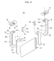
- FIG. 4 illustrates a partial exploded perspective view of a rechargeable battery according to a variation of the first example embodiment.
- a rechargeable battery 101 according to the present example embodiment is the same as rechargeable battery 100 according to the first example embodiment, except for first and second separating members 81 and 91, such that the detailed description of the same structure as in the first example embodiment is omitted.
- the first separating member 81 according to the present example embodiment may include a first body portion 81a, a first protrusion portion 81b, and a first supporting unit 81 c.
- the second separating member 91 may include a second body portion 91a, a second protrusion portion 91b, and a second supporting unit 91 c.
- the first and second bodies 81a and 91a of the first and second separating members 81 and 91 may include first and second electrode receiving members 811a and 911a.
- the first and second protrusion portions 81b and 91b may include positive and negative terminal fixing grooves 811b and 911b.
- the coupling relation of the first and second separating members 81 and 91, the current collectors 40 and 50, and the electrode assembly 10 according to the present example embodiment, except for the first and second supporting units 81 c and 91 c, is the same as the coupling relation of the first and second separating members 80 and 90, the current collectors 40 and 50, and the electrode assembly 10 according to the first example embodiment such that the detailed description thereof is omitted.
- the first and second supporting units 81 c and 91c of the first and second separating members 81 and 91 may be protruded at the end positioned opposite to the one end of the first and second bodies 81a and 91a where the first and second protrusion portions 81b and 91b are positioned.
- the first and second supporting units 81 c and 91 c may be formed substantially perpendicular to the first and second bodies 81a and 91a. Accordingly, the first and second supporting units 81 c and 91 c according to the present example embodiment may be positioned between one surface of the lower portion of the electrode assembly 10 and the bottom of the case 20 such that the electrode assembly 10 and the case 20 may be physically separated.
- the first and second separating members 81 and 91 according to the present example embodiment may be made of the insulating material, for example the insulating resin.
- the first and second supporting units 81 c and 91c may be positioned between the electrode assembly 10 and the case 20 such that the electrode assembly 10 and the case 20 may be electrically separated.
- the electrode assembly 10 between the first and second separating members 81 and 91 according to the present example embodiment may be installed between the first and second separating members 81 and 91 to be stably fixed inside the case 20 such that it is possible for the electrode assembly 10 to be physically and electrically separated from one side of the upper portion and the lower portion of the case 20.
- FIG. 5 illustrates a partial exploded perspective view of a rechargeable battery according to the second example embodiment.
- the rechargeable battery 200 according to the present example embodiment has the same structure as the rechargeable battery 100 according to the first example embodiment, except for a fixing plate 82, such that the detailed description for the same structure as in the rechargeable battery 100 according to the first example embodiment is omitted.
- the fixing plate 82 according to the present example embodiment may have a thin plate shape and may be coupled to one side of the first body portion 80a of the first separating member 80. In other implementations, the fixing plate 82 according to the present example embodiment can be coupled to one side of the second separating member 90 of the second body portion 90a, or may be extended at one side of each of the first and second separating members 80 and 90.
- the coupling relation of the first and second separating members 80 and 90 and the electrode assembly 10 is the same as that of the rechargeable battery 100 according to the first example embodiment such that the detailed description of the first and second separating members 80 and 90 and the electrode assembly 10 is omitted.
- the fixing plate 82 fixed to one side of the first separating member 80 is passed through or into a first fixing plate insertion element 42'a, also referred to as a current collector groove 42'a, which is formed at an electrode current collector coupling unit 42' of a positive current collector 40'.
- the first fixing plate insertion element 42'a can be a through-hole or a blind hole.
- the fixing plate 82 may be inserted into a gap formed in the center of one surface of the electrode assembly 10 where the positive electrode uncoated region 11a is formed.
- the fixing plate 82 according to the present example embodiment may be made of the insulating material, for example an insulating resin.
- the electrode assembly 10 may be supported between the first and second separating members 81 and 91 by the fixing plate 82 coupled to the first separating member 81.
- the electrode assembly 10 may be stably fixed inside the case 20.
- the positive electrode 11, the negative electrode 12, and the fixing plate 82 may be interposed between the separator 13 and then spiral-wound to form the electrode assembly 10.
- FIG. 6 illustrates a partial exploded perspective view of a rechargeable battery according to a variation of the second example embodiment.
- a rechargeable battery 201 according to the present example embodiment is the same as the rechargeable battery 100 according to the first example embodiment, except for a first fixing plate 83 and a second fixing plate 93 and positive and negative current collectors 40" and 50", such that the detailed description of the same structure is omitted.
- the first and second fixing plates 83 and 93 according to the present example embodiment may be formed with a thin plate shape.
- the first fixing plate 83 may be coupled to one side of the first separating member 80.
- the second fixing plate 93 may be coupled to one side of the second separating member 90.
- the coupling relation of the first and second separating members 80 and 90 and the electrode assembly 10 is the same as that of the rechargeable battery 100 according to the first example embodiment such that the detailed description thereof is omitted.
- the fixing plate 83 coupled to one side of the first separating member 80 may be passed through a first fixing plate insertion element 42"a, also referred to as a current collector groove 42"a formed at an electrode current collector coupling unit 42" of the positive current collector 40".
- the fixing plate 83 may be inserted into a gap formed at the center of one surface of the electrode assembly 10 where the positive electrode uncoated region 11a is formed.
- the second fixing plate 93 coupled to one side of the second separating member 90 may be passed through a first fixing plate insertion element 52"a, also referred to as a current collector groove 52"a formed at an electrode current collector coupling unit 52" of the negative current collector 50".
- the second fixing plate 93 may be inserted into a gap formed at the center of one surface of the electrode assembly 10 where the negative uncoated region 12a is formed. Accordingly, the first and second fixing plates 83 and 93 respectively coupled to the first and second separating members 80 and 90 may be inserted to both surfaces where the positive and negative uncoated regions 11a and 12a of the electrode assembly 10 are formed. Thus, the electrode assembly 10 may be stably fixed inside the case 20 and supported by the first and second fixing plates 83 and 93 between the first and second separating members 80 and 90.
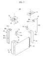
- FIG. 7 illustrates a partial exploded perspective view of a rechargeable battery according to another variation according to the second example embodiment.
- a rechargeable battery 202 may include the electrode assembly 10 and another electrode assembly 10'.
- a separating member 80' may include a fixing plate 82b and another fixing plate 82a extending from the separating member 80'.
- the fixing plate 82b may extend into a center region of the electrode assembly 10 and the other fixing plate 82a may extend into a center region of the other electrode assembly 10'.
- the fixing plates 82a, 82b may be configured to support the electrode assemblies 10', 10 along respective inner portions thereof.
- the fixing plates 82a, 82b may be formed as an integral unit as part of the separating member 80'.
- the fixing plates 82a, 82b, and the separating member 80' may be formed of an electrically insulating material.
- the separating member 80' may have a body portion 80'a, a protrusion portion 80'b, and an electrode receiving member 801'c.
- the fixing plates 82a, 82b may extend through respective openings 42"'b, 42"'a in a current collector 40"'.
- the current collector 40"' may have a body portion 42"' and a protrusion portion 41"' with a hole 41"'a therein, which may be used to couple to terminal 21.
- the terminal 21 may extend through an opening 801'b in the protrusion portion 80'b.
- An insulating member 60' may include terminal through-hole 62', a current collector receiving groove 61', and a flange receiving groove 63'.
- Another insulating member 70' may correspond to another separating member 90a, which may include a body portion 90'a, a protrusion portion 90'b, an electrode receiving member 901'a, and a terminal fixing groove 901'b
- a current collector 50"' may be disposed in the electrode receiving member 901'a.
- FIG. 8 illustrates a partial exploded perspective view of a rechargeable battery according to the third example embodiment.
- a rechargeable battery 300 according to the present example embodiment is the same structure as the rechargeable battery 100 according to the first example embodiment, except for a first separating member 84, such that the detailed description of the same structure as in the rechargeable battery 100 according to the first example embodiment is omitted.
- the first separating member 84 may include a first body portion 84a and a first protrusion portion 84b that is formed with a positive terminal fixing groove 841b.
- the first body portion 84a of the first separating member 84 may include an electrode receiving member 841a, and a pair of first fixing walls 84c extending from facing edges of the electrode receiving member 841a.
- the first fixing walls 84c may be made of the insulating material, for example an insulating resin.
- the first fixing walls 84c according to the present example embodiment may be extended from the second separating member 90, or may be extended from the first and second separating members 84 and 90.
- the coupling relation of the first and second separating members 84 and 90 and the electrode assembly 10 according to the present example embodiment is the same as the coupling relation of the first and second separating members 80 and 90 and the electrode assembly 10 according to the first example embodiment, except for the first fixing wall 84c formed at the first separating member 84, such that the detailed description is omitted.
- the electrode assembly 10 is inserted between a pair of first fixing walls 84c of the first body portion 84a of the first separating member 84 such that the electrode receiving member 841a may receive the portion of the electrode assembly 10 where the positive electrode uncoated region 11a is formed. Accordingly, according to the present example embodiment, the electrode assembly 10 may be physically and electrically separated from the case 20 by the first fixing wall 84c formed at the first separating member 84, and may be stably fixed inside the case 20.
- fixing plates and fixing walls may both be provided simultaneously, i.e. the embodiments of Fig. 5-7 may be combined with the embodiment of Fig. 8 .
- FIG. 9 illustrates a partial exploded perspective view of a rechargeable battery according to the fourth example embodiment
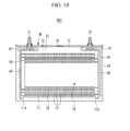
- FIG. 10 illustrates a cross-sectional view of a rechargeable battery according to the fourth example embodiment.
- the rechargeable battery 400 according to the present example embodiment has the same structure as the rechargeable battery 100 according to the first example embodiment, except for first and second separating members 85 and 95, such that the detailed description of the same structure as in the first example embodiment is omitted.
- the first and second separating members 85 and 95 may include first and second bodies 85a and 95a, and first and second lower insulators 85b and 95b including first and second electrode receiving member 851a and 951a.
- the first and second separating members 85 and 95 may be made of the insulating material, for example an insulating resin.
- the first and second lower insulators 85b and 95b may include first and second current collector receiving grooves 851b and 951b, first and second flange receiving grooves 852b and 952b, and first and second terminal through-holes 853b and 953b.
- the first and second lower insulators 85b and 95b may be extended perpendicular to the first and second bodies 85a and 95a.
- the first and second separating members 85 and 95 may have the same structure such that the detailed description of the coupling relation of the second separating member 95, the electrode assembly 10, the negative terminal 22, and the negative current collector 50 is omitted.
- the positive terminal 21 is passed through a first terminal through-hole 853b and may be fixed to the cap plate 31 by a nut, and the flange 21a may be received by the first flange receiving groove 852b.
- the terminal coupling groove 41a formed at the terminal coupling unit 41 of the current collector 40 may be inserted and welded with the coupling protrusion 21a.
- the first separating member 85 according to the present example embodiment may be fixed under the cap plate 31 by the flange 21a of the positive terminal 21.
- the first body portion 85a of the first separating member 85 may be positioned between the case 20 and one surface of the electrode assembly 10 where the positive electrode uncoated region 11a coupled with the current collector 40 is positioned. Accordingly, the first and second separating members 85 and 95 may be positioned between the cap plate 31 and the electrode assembly 10 and both sides of the case. Thus, the electrode assembly 10 and the case 20 may be physically and electrically separated.
- FIG. 11 illustrates a partial exploded perspective view of a rechargeable battery according to a variation according to the fourth example embodiment.
- the rechargeable battery 401 according to the present example embodiment has the same structure as the rechargeable battery 400 according to the fourth example embodiment, except for first and second separating members 86 and 96, such that the detailed description of the same structure is omitted.
- the first and second separating members 86 and 96 may include first and second bodies 86a and 96a (including first and second electrode receiving members 861a and 961a) and first and second lower insulators 86b and 96b, and may be made of the insulating material, for example an insulating resin.
- the first and second lower insulators 86b and 96b may include first and second current collector receiving grooves 861b and 961b, first and second flange receiving grooves 862b and 962b, and first and second terminal through-holes 863b and 963b.
- the first and second lower insulators 86b and 96b may be extended substantially perpendicular to the first and second bodies 86a and 96a.
- the coupling relation of the first and second separating member 86 and 96 and the electrode assembly 10, the positive electrode and negative terminals 21 and 22, and the positive and negative current collectors 40 and 50 according to the present example embodiment is the same as the coupling relation between the first and second separating members 85 and 95 and the electrode assembly 10, the positive and negative terminals 21 and 22, and the positive and the negative current collectors 40 and 50 according to the fourth example embodiment, except for the first and second supporting units 86c and 96c. Accordingly, the detailed description of the coupling relation of the first and second separating members 86 and 96 and the electrode assembly 10, the positive and negative terminals 21 and 22, and the positive and negative current collectors 40 and 50 is omitted.
- the first and second supporting units 86c and 96c of the first and second separating members 86 and 96 may be protruded at the other end positioned opposite to the end of the first and second bodies 86a and 96a where the first and second lower insulators 86b and 96b are positioned.
- the first and second supporting units 86c and 96c may be substantially perpendicular to the first and second bodies 86a and 96a.
- first and second supporting units 86c and 96c may be positioned between one surface of the lower portion of the electrode assembly 10 and the bottom surface of the case 20 such that the electrode assembly 10 and the case 20 may be physically separated.
- the first and second separating members 86 and 96 may be made of the insulating material, for example an insulating resin.
- the first and second supporting units 86c and 96c may be positioned between the electrode assembly 10 and the bottom portion of the case 20 such that the electrode assembly 10 and the case 20 may be electrically separated.
- the electrode assembly 10 may be installed between the first and second separating members 86 and 96, thereby being stably fixed inside the case 20 and being physically and electrically separated from one side, the upper portion, and the lower portion of the case 20.
- a rechargeable battery may be formed in various shapes, e.g., a cylindrical shape, a rectangular shape, etc.
- a plurality of large capacity rechargeable batteries may be connected in series and used for driving a motor for an electric vehicle.
- an electrode assembly housed within a case may be electrically connected to a current collector, and a terminal that protrudes outside the case may be electrically connected to the current collector such that a current generated in the electrode assembly may be provided to the outside.
- a space between the electrode assembly and the case is very small, an external impact on the case could be directly transmitted to the current collector, and the current collector could be damaged.
- the current collector (combined to an uncoated region of the electrode assembly) and the case may become electrically connected to each other such that the current generated in the electrode assembly may be shorted to the case.
- a separating member may protect the current collector in the event of an impact on the case, and may prevent the current collector from becoming electrically connected to the case in the event of such an impact.
- the separator may protect the electrode assembly in the event of an impact on the case.
- a separating member may be combined with a fixing plate or fixing walls to provide support and/or protection for the electrode assembly.
- the electrode assembly may be stably fixed inside the case by the separating member. Also, a short circuit of current generated in the electrode assembly to the outside of the case may be prevented. Accordingly, embodiments may provide a rechargeable battery stably fixing an electrode assembly inside a case and preventing a current generated in the electrode assembly from shorting to the case.
- the separating member may electrically and/or physically separate one or more electrode assemblies from the case.
Landscapes
- Chemical & Material Sciences (AREA)
- Chemical Kinetics & Catalysis (AREA)
- Electrochemistry (AREA)
- General Chemical & Material Sciences (AREA)
- Engineering & Computer Science (AREA)
- Manufacturing & Machinery (AREA)
- Connection Of Batteries Or Terminals (AREA)
- Secondary Cells (AREA)
- Sealing Battery Cases Or Jackets (AREA)
Applications Claiming Priority (2)
| Application Number | Priority Date | Filing Date | Title |
|---|---|---|---|
| US201161540226P | 2011-09-28 | 2011-09-28 | |
| US13/439,381 US9299972B2 (en) | 2011-09-28 | 2012-04-04 | Rechargeable battery with separating member between current collector and battery case |
Publications (3)
| Publication Number | Publication Date |
|---|---|
| EP2575190A2 true EP2575190A2 (de) | 2013-04-03 |
| EP2575190A3 EP2575190A3 (de) | 2014-08-20 |
| EP2575190B1 EP2575190B1 (de) | 2017-07-12 |
Family
ID=46603725
Family Applications (1)
| Application Number | Title | Priority Date | Filing Date |
|---|---|---|---|
| EP12178842.6A Active EP2575190B1 (de) | 2011-09-28 | 2012-08-01 | Wiederaufladbare Batterie |
Country Status (5)
| Country | Link |
|---|---|
| US (1) | US9299972B2 (de) |
| EP (1) | EP2575190B1 (de) |
| JP (1) | JP6084410B2 (de) |
| KR (1) | KR20130034578A (de) |
| CN (1) | CN103035855B (de) |
Cited By (3)
| Publication number | Priority date | Publication date | Assignee | Title |
|---|---|---|---|---|
| SE2351176A1 (en) * | 2023-10-12 | 2025-04-13 | Northvolt Ab | Battery cell with insulating element |
| US12463300B2 (en) | 2018-09-28 | 2025-11-04 | Panasonic Intellectual Property Management Co., Ltd. | Electricity storage device and electricity storage module |
| SE2430336A1 (en) * | 2024-06-19 | 2025-12-20 | Northvolt Ab | Improved insulator for a battery cell |
Families Citing this family (24)
| Publication number | Priority date | Publication date | Assignee | Title |
|---|---|---|---|---|
| JP5935878B2 (ja) * | 2012-04-17 | 2016-06-15 | 株式会社豊田自動織機 | 蓄電装置 |
| US10333113B2 (en) * | 2013-06-19 | 2019-06-25 | Samsung Sdi Co., Ltd. | Rechargeable battery having retainer |
| KR101724013B1 (ko) * | 2013-09-24 | 2017-04-06 | 삼성에스디아이 주식회사 | 결합이 용이한 단자 구조를 가지는 이차전지 |
| JP6502609B2 (ja) * | 2013-09-26 | 2019-04-17 | 株式会社Gsユアサ | 蓄電素子 |
| JP6187148B2 (ja) * | 2013-10-24 | 2017-08-30 | 株式会社Gsユアサ | 蓄電素子及び電源モジュール |
| JP6519161B2 (ja) | 2014-01-17 | 2019-05-29 | 株式会社Gsユアサ | 蓄電素子 |
| JP2015170414A (ja) * | 2014-03-05 | 2015-09-28 | 株式会社Gsユアサ | 蓄電素子 |
| JP6535982B2 (ja) * | 2014-06-13 | 2019-07-03 | 株式会社Gsユアサ | 蓄電素子 |
| KR102273643B1 (ko) | 2014-10-07 | 2021-07-07 | 삼성에스디아이 주식회사 | 이차 전지 |
| KR102284572B1 (ko) * | 2014-10-07 | 2021-08-03 | 삼성에스디아이 주식회사 | 이차 전지 |
| WO2016084693A1 (ja) * | 2014-11-28 | 2016-06-02 | 株式会社 豊田自動織機 | 蓄電装置 |
| KR102483338B1 (ko) | 2015-05-15 | 2023-01-02 | 삼성에스디아이 주식회사 | 이차 전지 |
| KR102524471B1 (ko) * | 2015-09-18 | 2023-04-24 | 삼성에스디아이 주식회사 | 이차전지 |
| KR102496391B1 (ko) * | 2015-11-11 | 2023-02-06 | 삼성에스디아이 주식회사 | 이차 전지 |
| JP6880483B2 (ja) * | 2017-01-27 | 2021-06-02 | 株式会社Gsユアサ | 蓄電素子 |
| JP6972583B2 (ja) * | 2017-03-07 | 2021-11-24 | 株式会社Gsユアサ | 蓄電素子 |
| JP7320165B2 (ja) * | 2018-03-23 | 2023-08-03 | パナソニックエナジー株式会社 | 二次電池 |
| US20230112577A1 (en) * | 2020-03-25 | 2023-04-13 | Gs Yuasa International Ltd. | Energy storage device |
| JP7070596B2 (ja) * | 2020-03-26 | 2022-05-18 | 株式会社Gsユアサ | 蓄電素子 |
| AU2021273919A1 (en) | 2020-05-22 | 2022-10-06 | Duracell U.S. Operations, Inc. | Seal assembly for a battery cell |
| CN113394493A (zh) * | 2021-06-25 | 2021-09-14 | 银隆新能源股份有限公司 | 锂离子电池及具有其的电动车 |
| EP4510284A4 (de) * | 2022-07-21 | 2025-08-20 | Contemporary Amperex Technology Co Ltd | Batteriezelle, batterie und elektrische vorrichtung |
| SE2250961A1 (en) * | 2022-08-12 | 2024-02-13 | Northvolt Ab | Battery cell with insulating element |
| CN117096514B (zh) * | 2023-10-20 | 2024-03-29 | 江苏时代新能源科技有限公司 | 顶盖组件、电池及用电设备 |
Family Cites Families (12)
| Publication number | Priority date | Publication date | Assignee | Title |
|---|---|---|---|---|
| JPS4722440U (de) | 1971-03-23 | 1972-11-13 | ||
| JPH0722440U (ja) | 1993-09-30 | 1995-04-21 | 市光工業株式会社 | 車両用灯具のスイッチ装置 |
| US6610444B2 (en) * | 2000-09-29 | 2003-08-26 | Sanyo Electric Co., Ltd. | Secondary cell with non-rotatable terminal member |
| KR100599709B1 (ko) * | 2004-07-28 | 2006-07-12 | 삼성에스디아이 주식회사 | 이차 전지 |
| KR101011179B1 (ko) | 2005-09-13 | 2011-01-26 | 히다치 막셀 가부시키가이샤 | 밀폐 각형 전지 |
| JP5096671B2 (ja) | 2005-09-13 | 2012-12-12 | 日立マクセルエナジー株式会社 | 密閉角形電池 |
| KR20090035328A (ko) | 2007-10-05 | 2009-04-09 | 주식회사 씨엠파트너 | 스웰링에 의한 극판 변형을 방지하는 구조의 극판 압착판을갖는 전극조립체 및 이를 이용한 전지 |
| JP5522507B2 (ja) * | 2009-06-23 | 2014-06-18 | 株式会社Gsユアサ | 電池 |
| KR101097221B1 (ko) * | 2009-10-30 | 2011-12-21 | 에스비리모티브 주식회사 | 이차전지 |
| JP2011108507A (ja) * | 2009-11-18 | 2011-06-02 | Honda Motor Co Ltd | 二次電池 |
| KR101036089B1 (ko) * | 2010-01-27 | 2011-05-19 | 에스비리모티브 주식회사 | 절연 백을 갖는 이차전지 |
| EP2549562B1 (de) * | 2010-06-21 | 2016-12-14 | Kabushiki Kaisha Toshiba | Batterie |
-
2012
- 2012-04-04 US US13/439,381 patent/US9299972B2/en active Active
- 2012-07-23 KR KR1020120080225A patent/KR20130034578A/ko not_active Ceased
- 2012-08-01 EP EP12178842.6A patent/EP2575190B1/de active Active
- 2012-09-07 CN CN201210331467.5A patent/CN103035855B/zh active Active
- 2012-09-14 JP JP2012203257A patent/JP6084410B2/ja active Active
Non-Patent Citations (1)
| Title |
|---|
| None |
Cited By (4)
| Publication number | Priority date | Publication date | Assignee | Title |
|---|---|---|---|---|
| US12463300B2 (en) | 2018-09-28 | 2025-11-04 | Panasonic Intellectual Property Management Co., Ltd. | Electricity storage device and electricity storage module |
| SE2351176A1 (en) * | 2023-10-12 | 2025-04-13 | Northvolt Ab | Battery cell with insulating element |
| SE547943C2 (en) * | 2023-10-12 | 2025-12-23 | Northvolt Ab | Battery cell with insulating element |
| SE2430336A1 (en) * | 2024-06-19 | 2025-12-20 | Northvolt Ab | Improved insulator for a battery cell |
Also Published As
| Publication number | Publication date |
|---|---|
| KR20130034578A (ko) | 2013-04-05 |
| JP6084410B2 (ja) | 2017-02-22 |
| CN103035855B (zh) | 2017-08-04 |
| JP2013073936A (ja) | 2013-04-22 |
| CN103035855A (zh) | 2013-04-10 |
| US9299972B2 (en) | 2016-03-29 |
| EP2575190A3 (de) | 2014-08-20 |
| EP2575190B1 (de) | 2017-07-12 |
| US20130078505A1 (en) | 2013-03-28 |
Similar Documents
| Publication | Publication Date | Title |
|---|---|---|
| EP2575190A2 (de) | Wiederaufladbare Batterie | |
| EP2557609B1 (de) | Wieder aufladbare Batterie und Herstellungsverfahren dafür | |
| EP2299511B1 (de) | Wiederaufladbare Batterie und Batteriemodul | |
| EP3168898B1 (de) | Wiederaufladbares batteriemodul | |
| US9178204B2 (en) | Rechargeable battery | |
| JP4519063B2 (ja) | 二次電池 | |
| CN103367668B (zh) | 电池 | |
| EP2562842B1 (de) | Batteriemodul | |
| KR101509474B1 (ko) | 단일 전극단자 결합부를 가진 전지 조합체 | |
| KR101155888B1 (ko) | 이차 전지 | |
| EP2736097B1 (de) | Wiederaufladbare Batterie und Modul daraus | |
| US9312528B2 (en) | Rechargeable battery and battery module | |
| KR102361705B1 (ko) | 커버를 갖는 이차 전지 | |
| CN105322210A (zh) | 可再充电电池 | |
| US8999569B2 (en) | Rechargeable battery including a terminal connecting member | |
| EP2551938A1 (de) | Verbindung zwischen einem Pol und einem Gehäusedeckel in einer wiederaufladbaren Batterie | |
| US20130115494A1 (en) | Rechargeable battery | |
| JP2011119265A (ja) | 二次電池 | |
| KR101147176B1 (ko) | 이차전지 | |
| US10014495B2 (en) | Rechargeable battery | |
| KR102296817B1 (ko) | 이차 전지 |
Legal Events
| Date | Code | Title | Description |
|---|---|---|---|
| PUAI | Public reference made under article 153(3) epc to a published international application that has entered the european phase |
Free format text: ORIGINAL CODE: 0009012 |
|
| AK | Designated contracting states |
Kind code of ref document: A2 Designated state(s): AL AT BE BG CH CY CZ DE DK EE ES FI FR GB GR HR HU IE IS IT LI LT LU LV MC MK MT NL NO PL PT RO RS SE SI SK SM TR |
|
| AX | Request for extension of the european patent |
Extension state: BA ME |
|
| REG | Reference to a national code |
Ref country code: DE Ref legal event code: R079 Ref document number: 602012034358 Country of ref document: DE Free format text: PREVIOUS MAIN CLASS: H01M0002060000 Ipc: H01M0002180000 |
|
| PUAL | Search report despatched |
Free format text: ORIGINAL CODE: 0009013 |
|
| AK | Designated contracting states |
Kind code of ref document: A3 Designated state(s): AL AT BE BG CH CY CZ DE DK EE ES FI FR GB GR HR HU IE IS IT LI LT LU LV MC MK MT NL NO PL PT RO RS SE SI SK SM TR |
|
| AX | Request for extension of the european patent |
Extension state: BA ME |
|
| RIC1 | Information provided on ipc code assigned before grant |
Ipc: H01M 2/06 20060101ALN20140711BHEP Ipc: H01M 2/02 20060101ALN20140711BHEP Ipc: H01M 10/04 20060101ALI20140711BHEP Ipc: H01M 2/26 20060101ALI20140711BHEP Ipc: H01M 10/0587 20100101ALN20140711BHEP Ipc: H01M 2/18 20060101AFI20140711BHEP |
|
| 17P | Request for examination filed |
Effective date: 20150216 |
|
| RBV | Designated contracting states (corrected) |
Designated state(s): AL AT BE BG CH CY CZ DE DK EE ES FI FR GB GR HR HU IE IS IT LI LT LU LV MC MK MT NL NO PL PT RO RS SE SI SK SM TR |
|
| GRAP | Despatch of communication of intention to grant a patent |
Free format text: ORIGINAL CODE: EPIDOSNIGR1 |
|
| STAA | Information on the status of an ep patent application or granted ep patent |
Free format text: STATUS: GRANT OF PATENT IS INTENDED |
|
| INTG | Intention to grant announced |
Effective date: 20170202 |
|
| GRAS | Grant fee paid |
Free format text: ORIGINAL CODE: EPIDOSNIGR3 |
|
| GRAA | (expected) grant |
Free format text: ORIGINAL CODE: 0009210 |
|
| STAA | Information on the status of an ep patent application or granted ep patent |
Free format text: STATUS: THE PATENT HAS BEEN GRANTED |
|
| AK | Designated contracting states |
Kind code of ref document: B1 Designated state(s): AL AT BE BG CH CY CZ DE DK EE ES FI FR GB GR HR HU IE IS IT LI LT LU LV MC MK MT NL NO PL PT RO RS SE SI SK SM TR |
|
| REG | Reference to a national code |
Ref country code: GB Ref legal event code: FG4D |
|
| REG | Reference to a national code |
Ref country code: CH Ref legal event code: EP |
|
| REG | Reference to a national code |
Ref country code: AT Ref legal event code: REF Ref document number: 909125 Country of ref document: AT Kind code of ref document: T Effective date: 20170715 |
|
| REG | Reference to a national code |
Ref country code: IE Ref legal event code: FG4D |
|
| REG | Reference to a national code |
Ref country code: FR Ref legal event code: PLFP Year of fee payment: 6 |
|
| REG | Reference to a national code |
Ref country code: DE Ref legal event code: R096 Ref document number: 602012034358 Country of ref document: DE |
|
| REG | Reference to a national code |
Ref country code: NL Ref legal event code: MP Effective date: 20170712 |
|
| REG | Reference to a national code |
Ref country code: LT Ref legal event code: MG4D |
|
| REG | Reference to a national code |
Ref country code: AT Ref legal event code: MK05 Ref document number: 909125 Country of ref document: AT Kind code of ref document: T Effective date: 20170712 |
|
| PG25 | Lapsed in a contracting state [announced via postgrant information from national office to epo] |
Ref country code: SE Free format text: LAPSE BECAUSE OF FAILURE TO SUBMIT A TRANSLATION OF THE DESCRIPTION OR TO PAY THE FEE WITHIN THE PRESCRIBED TIME-LIMIT Effective date: 20170712 Ref country code: LT Free format text: LAPSE BECAUSE OF FAILURE TO SUBMIT A TRANSLATION OF THE DESCRIPTION OR TO PAY THE FEE WITHIN THE PRESCRIBED TIME-LIMIT Effective date: 20170712 Ref country code: NL Free format text: LAPSE BECAUSE OF FAILURE TO SUBMIT A TRANSLATION OF THE DESCRIPTION OR TO PAY THE FEE WITHIN THE PRESCRIBED TIME-LIMIT Effective date: 20170712 Ref country code: AT Free format text: LAPSE BECAUSE OF FAILURE TO SUBMIT A TRANSLATION OF THE DESCRIPTION OR TO PAY THE FEE WITHIN THE PRESCRIBED TIME-LIMIT Effective date: 20170712 Ref country code: HR Free format text: LAPSE BECAUSE OF FAILURE TO SUBMIT A TRANSLATION OF THE DESCRIPTION OR TO PAY THE FEE WITHIN THE PRESCRIBED TIME-LIMIT Effective date: 20170712 Ref country code: FI Free format text: LAPSE BECAUSE OF FAILURE TO SUBMIT A TRANSLATION OF THE DESCRIPTION OR TO PAY THE FEE WITHIN THE PRESCRIBED TIME-LIMIT Effective date: 20170712 Ref country code: NO Free format text: LAPSE BECAUSE OF FAILURE TO SUBMIT A TRANSLATION OF THE DESCRIPTION OR TO PAY THE FEE WITHIN THE PRESCRIBED TIME-LIMIT Effective date: 20171012 |
|
| PG25 | Lapsed in a contracting state [announced via postgrant information from national office to epo] |
Ref country code: BG Free format text: LAPSE BECAUSE OF FAILURE TO SUBMIT A TRANSLATION OF THE DESCRIPTION OR TO PAY THE FEE WITHIN THE PRESCRIBED TIME-LIMIT Effective date: 20171012 Ref country code: PL Free format text: LAPSE BECAUSE OF FAILURE TO SUBMIT A TRANSLATION OF THE DESCRIPTION OR TO PAY THE FEE WITHIN THE PRESCRIBED TIME-LIMIT Effective date: 20170712 Ref country code: LV Free format text: LAPSE BECAUSE OF FAILURE TO SUBMIT A TRANSLATION OF THE DESCRIPTION OR TO PAY THE FEE WITHIN THE PRESCRIBED TIME-LIMIT Effective date: 20170712 Ref country code: ES Free format text: LAPSE BECAUSE OF FAILURE TO SUBMIT A TRANSLATION OF THE DESCRIPTION OR TO PAY THE FEE WITHIN THE PRESCRIBED TIME-LIMIT Effective date: 20170712 Ref country code: GR Free format text: LAPSE BECAUSE OF FAILURE TO SUBMIT A TRANSLATION OF THE DESCRIPTION OR TO PAY THE FEE WITHIN THE PRESCRIBED TIME-LIMIT Effective date: 20171013 Ref country code: IS Free format text: LAPSE BECAUSE OF FAILURE TO SUBMIT A TRANSLATION OF THE DESCRIPTION OR TO PAY THE FEE WITHIN THE PRESCRIBED TIME-LIMIT Effective date: 20171112 Ref country code: RS Free format text: LAPSE BECAUSE OF FAILURE TO SUBMIT A TRANSLATION OF THE DESCRIPTION OR TO PAY THE FEE WITHIN THE PRESCRIBED TIME-LIMIT Effective date: 20170712 |
|
| REG | Reference to a national code |
Ref country code: CH Ref legal event code: PL |
|
| REG | Reference to a national code |
Ref country code: DE Ref legal event code: R097 Ref document number: 602012034358 Country of ref document: DE |
|
| PG25 | Lapsed in a contracting state [announced via postgrant information from national office to epo] |
Ref country code: CH Free format text: LAPSE BECAUSE OF NON-PAYMENT OF DUE FEES Effective date: 20170831 Ref country code: DK Free format text: LAPSE BECAUSE OF FAILURE TO SUBMIT A TRANSLATION OF THE DESCRIPTION OR TO PAY THE FEE WITHIN THE PRESCRIBED TIME-LIMIT Effective date: 20170712 Ref country code: MC Free format text: LAPSE BECAUSE OF FAILURE TO SUBMIT A TRANSLATION OF THE DESCRIPTION OR TO PAY THE FEE WITHIN THE PRESCRIBED TIME-LIMIT Effective date: 20170712 Ref country code: LI Free format text: LAPSE BECAUSE OF NON-PAYMENT OF DUE FEES Effective date: 20170831 Ref country code: RO Free format text: LAPSE BECAUSE OF FAILURE TO SUBMIT A TRANSLATION OF THE DESCRIPTION OR TO PAY THE FEE WITHIN THE PRESCRIBED TIME-LIMIT Effective date: 20170712 Ref country code: CZ Free format text: LAPSE BECAUSE OF FAILURE TO SUBMIT A TRANSLATION OF THE DESCRIPTION OR TO PAY THE FEE WITHIN THE PRESCRIBED TIME-LIMIT Effective date: 20170712 |
|
| PLBE | No opposition filed within time limit |
Free format text: ORIGINAL CODE: 0009261 |
|
| STAA | Information on the status of an ep patent application or granted ep patent |
Free format text: STATUS: NO OPPOSITION FILED WITHIN TIME LIMIT |
|
| REG | Reference to a national code |
Ref country code: IE Ref legal event code: MM4A |
|
| PG25 | Lapsed in a contracting state [announced via postgrant information from national office to epo] |
Ref country code: EE Free format text: LAPSE BECAUSE OF FAILURE TO SUBMIT A TRANSLATION OF THE DESCRIPTION OR TO PAY THE FEE WITHIN THE PRESCRIBED TIME-LIMIT Effective date: 20170712 Ref country code: SK Free format text: LAPSE BECAUSE OF FAILURE TO SUBMIT A TRANSLATION OF THE DESCRIPTION OR TO PAY THE FEE WITHIN THE PRESCRIBED TIME-LIMIT Effective date: 20170712 Ref country code: SM Free format text: LAPSE BECAUSE OF FAILURE TO SUBMIT A TRANSLATION OF THE DESCRIPTION OR TO PAY THE FEE WITHIN THE PRESCRIBED TIME-LIMIT Effective date: 20170712 Ref country code: IT Free format text: LAPSE BECAUSE OF FAILURE TO SUBMIT A TRANSLATION OF THE DESCRIPTION OR TO PAY THE FEE WITHIN THE PRESCRIBED TIME-LIMIT Effective date: 20170712 |
|
| REG | Reference to a national code |
Ref country code: BE Ref legal event code: MM Effective date: 20170831 |
|
| 26N | No opposition filed |
Effective date: 20180413 |
|
| PG25 | Lapsed in a contracting state [announced via postgrant information from national office to epo] |
Ref country code: LU Free format text: LAPSE BECAUSE OF NON-PAYMENT OF DUE FEES Effective date: 20170801 |
|
| REG | Reference to a national code |
Ref country code: FR Ref legal event code: PLFP Year of fee payment: 7 |
|
| PG25 | Lapsed in a contracting state [announced via postgrant information from national office to epo] |
Ref country code: IE Free format text: LAPSE BECAUSE OF NON-PAYMENT OF DUE FEES Effective date: 20170801 |
|
| PG25 | Lapsed in a contracting state [announced via postgrant information from national office to epo] |
Ref country code: BE Free format text: LAPSE BECAUSE OF NON-PAYMENT OF DUE FEES Effective date: 20170831 Ref country code: SI Free format text: LAPSE BECAUSE OF FAILURE TO SUBMIT A TRANSLATION OF THE DESCRIPTION OR TO PAY THE FEE WITHIN THE PRESCRIBED TIME-LIMIT Effective date: 20170712 |
|
| PG25 | Lapsed in a contracting state [announced via postgrant information from national office to epo] |
Ref country code: MT Free format text: LAPSE BECAUSE OF NON-PAYMENT OF DUE FEES Effective date: 20170801 |
|
| PG25 | Lapsed in a contracting state [announced via postgrant information from national office to epo] |
Ref country code: HU Free format text: LAPSE BECAUSE OF FAILURE TO SUBMIT A TRANSLATION OF THE DESCRIPTION OR TO PAY THE FEE WITHIN THE PRESCRIBED TIME-LIMIT; INVALID AB INITIO Effective date: 20120801 |
|
| PG25 | Lapsed in a contracting state [announced via postgrant information from national office to epo] |
Ref country code: CY Free format text: LAPSE BECAUSE OF NON-PAYMENT OF DUE FEES Effective date: 20170712 |
|
| PG25 | Lapsed in a contracting state [announced via postgrant information from national office to epo] |
Ref country code: MK Free format text: LAPSE BECAUSE OF FAILURE TO SUBMIT A TRANSLATION OF THE DESCRIPTION OR TO PAY THE FEE WITHIN THE PRESCRIBED TIME-LIMIT Effective date: 20170712 |
|
| PG25 | Lapsed in a contracting state [announced via postgrant information from national office to epo] |
Ref country code: TR Free format text: LAPSE BECAUSE OF FAILURE TO SUBMIT A TRANSLATION OF THE DESCRIPTION OR TO PAY THE FEE WITHIN THE PRESCRIBED TIME-LIMIT Effective date: 20170712 |
|
| PG25 | Lapsed in a contracting state [announced via postgrant information from national office to epo] |
Ref country code: PT Free format text: LAPSE BECAUSE OF FAILURE TO SUBMIT A TRANSLATION OF THE DESCRIPTION OR TO PAY THE FEE WITHIN THE PRESCRIBED TIME-LIMIT Effective date: 20170712 |
|
| PG25 | Lapsed in a contracting state [announced via postgrant information from national office to epo] |
Ref country code: AL Free format text: LAPSE BECAUSE OF FAILURE TO SUBMIT A TRANSLATION OF THE DESCRIPTION OR TO PAY THE FEE WITHIN THE PRESCRIBED TIME-LIMIT Effective date: 20170712 |
|
| REG | Reference to a national code |
Ref country code: DE Ref legal event code: R079 Ref document number: 602012034358 Country of ref document: DE Free format text: PREVIOUS MAIN CLASS: H01M0002180000 Ipc: H01M0050463000 |
|
| P01 | Opt-out of the competence of the unified patent court (upc) registered |
Effective date: 20230530 |
|
| PGFP | Annual fee paid to national office [announced via postgrant information from national office to epo] |
Ref country code: DE Payment date: 20250805 Year of fee payment: 14 |
|
| PGFP | Annual fee paid to national office [announced via postgrant information from national office to epo] |
Ref country code: GB Payment date: 20250731 Year of fee payment: 14 |
|
| PGFP | Annual fee paid to national office [announced via postgrant information from national office to epo] |
Ref country code: FR Payment date: 20250808 Year of fee payment: 14 |