EP2575212A1 - Antenne - Google Patents
Antenne Download PDFInfo
- Publication number
- EP2575212A1 EP2575212A1 EP20120179298 EP12179298A EP2575212A1 EP 2575212 A1 EP2575212 A1 EP 2575212A1 EP 20120179298 EP20120179298 EP 20120179298 EP 12179298 A EP12179298 A EP 12179298A EP 2575212 A1 EP2575212 A1 EP 2575212A1
- Authority
- EP
- European Patent Office
- Prior art keywords
- antenna
- radiating part
- conductive member
- radiating
- feeding
- Prior art date
- Legal status (The legal status is an assumption and is not a legal conclusion. Google has not performed a legal analysis and makes no representation as to the accuracy of the status listed.)
- Granted
Links
Images

Classifications
-
- H—ELECTRICITY
- H01—ELECTRIC ELEMENTS
- H01Q—ANTENNAS, i.e. RADIO AERIALS
- H01Q9/00—Electrically-short antennas having dimensions not more than twice the operating wavelength and consisting of conductive active radiating elements
- H01Q9/04—Resonant antennas
- H01Q9/0407—Substantially flat resonant element parallel to ground plane, e.g. patch antenna
- H01Q9/0421—Substantially flat resonant element parallel to ground plane, e.g. patch antenna with a shorting wall or a shorting pin at one end of the element
-
- H—ELECTRICITY
- H01—ELECTRIC ELEMENTS
- H01Q—ANTENNAS, i.e. RADIO AERIALS
- H01Q1/00—Details of, or arrangements associated with, antennas
- H01Q1/44—Details of, or arrangements associated with, antennas using equipment having another main function to serve additionally as an antenna, e.g. means for giving an antenna an aesthetic aspect
- H01Q1/46—Electric supply lines or communication lines
-
- H—ELECTRICITY
- H01—ELECTRIC ELEMENTS
- H01Q—ANTENNAS, i.e. RADIO AERIALS
- H01Q5/00—Arrangements for simultaneous operation of antennas on two or more different wavebands, e.g. dual-band or multi-band arrangements
- H01Q5/40—Imbricated or interleaved structures; Combined or electromagnetically coupled arrangements, e.g. comprising two or more non-connected fed radiating elements
-
- H—ELECTRICITY
- H01—ELECTRIC ELEMENTS
- H01Q—ANTENNAS, i.e. RADIO AERIALS
- H01Q7/00—Loop antennas with a substantially uniform current distribution around the loop and having a directional radiation pattern in a plane perpendicular to the plane of the loop
-
- H—ELECTRICITY
- H01—ELECTRIC ELEMENTS
- H01Q—ANTENNAS, i.e. RADIO AERIALS
- H01Q9/00—Electrically-short antennas having dimensions not more than twice the operating wavelength and consisting of conductive active radiating elements
- H01Q9/04—Resonant antennas
- H01Q9/0407—Substantially flat resonant element parallel to ground plane, e.g. patch antenna
- H01Q9/045—Substantially flat resonant element parallel to ground plane, e.g. patch antenna with particular feeding means
Definitions
- the disclosure relates to an antenna having a circular feeding structure.
- the disclosure relates to an antenna which can optimize the impedance matching in the power feeding between antennas by utilizing a circular feeding structure, increase the efficiency of the antenna by allowing a feeding line to serve as another antenna, and perform beam forming.
- a radiating element constituting the antenna can be formed with a length corresponding to 4/1 of a wavelength at a resonance frequency in the low frequency band.
- Compacter antennas for a broad band have been required, and antennas usable in a wider frequency band have been required.
- the disclosure is to provide a high-efficiency small antenna to various wireless appliances by utilizing a conventional feeding line to a circular feeding coupling to act as one independent antenna, so that the feeding line acts as an array antenna together with an antenna mounted on the feeding line.
- an antenna including a first radiating part bent in a predetermined direction, a second radiating part under the first radiating part, a conductive member connected to the second radiating part, and a coupling part spaced apart from the conductive member while surrounding a lateral side of the conductive member.
- the circular feeding coupling antenna of the disclosure has the following effects.
- the circular feeding coupling antenna is utilized as an antenna different from an antenna mounted on an antenna feeding line, so that the two antennas serves as an array antenna, thereby increasing the antenna efficiency.
- a part of an antenna mounted on the feeding line acts as a feeding line antenna, so that the electrical length of the antenna can be reduced.
- the impedance matching for a broader band can be achieved by using a coupling.
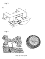
- FIG. 1 is an exploded perspective view showing components of an antenna according to the embodiment of the disclosure
- FIG. 2 is a partial enlarged view of a part A of FIG. 1 ;
- FIG. 3 is a perspective view showing the coupling of the components of an antenna according to the embodiment of the disclosure.
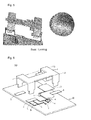
- FIGS. 4 and 5 are views showing the radiation shape of the antenna according to the embodiment of the present invention.
- FIG. 6 is an exploded perspective view showing components of an antenna according to another embodiment of the disclosure.
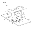
- FIG. 7 is an exploded perspective view showing components of an antenna according to still another embodiment of the disclosure.
- FIG. 1 is an exploded perspective view showing components of an antenna according to the embodiment of the disclosure
- FIG. 2 is a partial enlarged view of a part A of FIG. 1
- FIG. 3 is a perspective view showing the coupling of the components of an antenna according to the embodiment of the disclosure.
- a broadband embedded antenna device 100 may include an antenna part and a substrate 20.
- the antenna part may be provided on a feeding part 3.
- the antenna part may include a first radiating part 1, a second radiating part 2, a feeding part 3, a coupling part 4, a first radiating part mounting part 5, and a conductive member 6.
- the first and second radiating parts 1 and 2 may be connected to a grounding part and the feeding part 3, respectively.
- the substrate 20 may include at least one of epoxy, duroid, Teflon, baklite, high-resistance silicon, glass, alumina, LTCC, and air form, but the disclosure is not limited thereto.
- the first and second radiating parts 1 and 2 radiate RF signals having a preset frequency band to the outside, and receive RF signals having a preset frequency band from the outside.
- the first radiating part 1 is mounted on the first radiating part mounting part 5 so that the first radiating part 1 can be connected to the second radiating part 2.
- the first and second radiating parts 1 and 2 may include the same material.
- the first radiating part 1 may be bent at a right angle along two bending lines 110 and 120.
- the two bending lines 110 and 120 may include virtual lines to bend the first radiating part 1.
- the first radiating part 1 may be bent in the same direction along the two bending lines 110 and 120.
- the first radiating part 1 may be bent at the right angle along the two bending lines 110 and 120. Accordingly, the space necessary to mount an antenna may be reduced.
- the first radiating part 1 may include a metallic plate having a meander line structure so that the antenna can be realized in a limited space.
- the disclosure has been described in that the first radiating part 1 is bent at the right angle, the bending angle of the first radiating part 1 may be more than the right angle or less than the right angle.
- the dimension of the first radiating part 1 or the second radiating part 2 may be varied according to the resonance frequency or the wavelength.
- the antenna device 100 may include an internal antenna used in a cellular terminal (e.g., mobile communication terminal), or PDA (Personal Digital Assistant).
- a cellular terminal e.g., mobile communication terminal
- PDA Personal Digital Assistant
- the resonance in the fundamental band and/or the resonance at a higher band may be additionally provided by the second radiating part 2.
- the second radiating part 2 may have a substantially loop shape, so that the resonance in the fundamental band and/or the resonance at a higher band may be additionally provided.
- the second radiating part 2 may have the conductive member 6 at the bending part.
- the second radiating part 2 may be connected in the bending state due to the conductive member 6.
- the second radiating part 2 may be connected to the first radiating part mounting part 5.
- the coupling part 4 may have a closed loop shape (or ring).
- the coupling structure A may exert an influence on the electrical characteristic (especially, impedance matching) of the antenna device 100 at all frequency bands.
- the coupling part 4 and the conductive member 6 are spaced apart from each other by a predetermined distance d to perform impedance matching.
- the coupling part 4 may have the shape of "O” as show in FIG. 2
- the coupling part 4 may have the shape of "C".
- the disclosure is not limited thereto.
- the coupling part 4 may be applied to a stack-type antenna.
- the coupling part may be applied to a double-side antenna.
- the conductive member 6 has a cylindrical shape, the embodiment is not limited thereto.
- the conductive member 6 is connected to the second radiating part 2, and spaced apart from the coupling part.
- the whole interval d and a radius r of the conductive member 6 are adjusted by taking the whole size and the internal space of a terminal equipped with an antenna into consideration.
- the interval d and the radius r of the conductive member 6 are variously set, so that the diversity of a capacitor component can be more maximized. Accordingly, the interval d and the radius r of the conductive member 6 may be variously modified and applied. For example, one of the interval d and the radius r of the conductive member 6 may be modified, or both of the interval d and the radius r of the conductive member 6 can be modified.
- the second radiating part 2 connected to the coupling part 4 may be horizontal to the second radiating part 2 connected to the conductive member 6.
- impedance matching can be achieved at a broader band through the coupling matching occurring in the structure in which the coupling part 4 is spaced apart from the conductive member 6 by a predetermined distance d.
- a conventional inverse-F antenna has a structure of achieving only point matching through a grounding pin. According to the matching scheme, sufficient matching at a broad band does not occur. In contrast, in the coupling matching structure of the present invention, impedance matching can be achieved at the broader band.
- the impedance matching can be achieved due to the capacitor coupling in the coupling structure, and the capacitance may be varied according to the interval d. For example, if the interval d is increased, the capacitance may be increased. In addition, the electrical length of the first radiating part 1 can be reduced due to the coupling structure.
- FIGS. 4 and 5 are views showing the radiation shape of the antenna according to the embodiment.
- FIG. 4 is a view showing an external antenna.
- the second radiating part 2 may have a point symmetry structure. If the second radiating part 2 has a point symmetry structure, the coupling part 4 may have the shape of "O".
- FIG. 5 is a view showing an embedded antenna.
- the second radiating part 2 may have a plane symmetry structure. If the second radiating part 2 has a plane symmetry structure, the coupling part 4 may have the shape of "C".
- FIG. 6 is an exploded perspective view showing components of the antenna according to another embodiment of the disclosure.
- a plurality of feeding parts 3 are provided, and the feeding part 3 may be connected to the first radiating part mounting part 5.
- the feeding part 3 including first and second feeding parts L and M in parallel to each other may be connected to the first radiating part mounting part 5.
- the first feeding part L may be aligned in line with the second feeing part M.
- the first and second feeding parts L and M may have the same width, but the embodiment is not limited thereto.
- the first and second feeding parts L and M may be formed on the same plane in parallel, or may be formed with a predetermined gradient.
- FIG. 7 is an exploded perspective view showing the components of an antenna according to still another embodiment of the disclosure. Different from the structure shown in FIG. 6 , the first and second feeding parts L and M are connected to each other in parallel while forming a predetermined height.
- the first and second feeding parts L and M may include the same material, and includes a conductive material.
- the size of the antenna may be reduced.
- any reference in this specification to "one embodiment,” “an embodiment,” “example embodiment,” etc. means that a particular feature, structure, or characteristic described in connection with the embodiment is included in at least one embodiment of the invention.
- the appearances of such phrases in various places in the specification are not necessarily all referring to the same embodiment.
Landscapes
- Physics & Mathematics (AREA)
- Electromagnetism (AREA)
- Details Of Aerials (AREA)
- Support Of Aerials (AREA)
Applications Claiming Priority (1)
| Application Number | Priority Date | Filing Date | Title |
|---|---|---|---|
| KR1020110098610A KR101316153B1 (ko) | 2011-09-28 | 2011-09-28 | 안테나 |
Publications (2)
| Publication Number | Publication Date |
|---|---|
| EP2575212A1 true EP2575212A1 (fr) | 2013-04-03 |
| EP2575212B1 EP2575212B1 (fr) | 2018-06-06 |
Family
ID=46679173
Family Applications (1)
| Application Number | Title | Priority Date | Filing Date |
|---|---|---|---|
| EP12179298.0A Active EP2575212B1 (fr) | 2011-09-28 | 2012-08-03 | Antenne |
Country Status (4)
| Country | Link |
|---|---|
| US (1) | US9373890B2 (fr) |
| EP (1) | EP2575212B1 (fr) |
| JP (1) | JP5535281B2 (fr) |
| KR (1) | KR101316153B1 (fr) |
Citations (5)
| Publication number | Priority date | Publication date | Assignee | Title |
|---|---|---|---|---|
| US5262792A (en) * | 1991-09-11 | 1993-11-16 | Harada Kogyo Kabushiki Kaisha | Shortened non-grounded type ultrashort-wave antenna |
| EP1091445A2 (fr) * | 1999-10-08 | 2001-04-11 | Matsushita Electric Industrial Co., Ltd. | Dispositif d'antenne et système de communication |
| US20030160726A1 (en) * | 2001-07-31 | 2003-08-28 | Grant Jerry Allen | Inverted safety antenna for personal communication devices |
| US20040051675A1 (en) * | 2001-11-16 | 2004-03-18 | Jinichi Inoue | Composite antenna |
| US20060227052A1 (en) * | 2005-04-07 | 2006-10-12 | X-Ether, Inc. | Multi-band or wide-band antenna |
Family Cites Families (8)
| Publication number | Priority date | Publication date | Assignee | Title |
|---|---|---|---|---|
| US3319141A (en) * | 1962-12-27 | 1967-05-09 | Union Carbide Corp | Thin film capacitors |
| US4741214A (en) * | 1986-09-19 | 1988-05-03 | Combustion Engineering, Inc. | Capacitive transducer with static compensation |
| US5349365A (en) * | 1991-10-21 | 1994-09-20 | Ow Steven G | Quadrifilar helix antenna |
| EP1978595B1 (fr) * | 2003-12-25 | 2011-03-23 | Mitsubishi Materials Corporation | Dispositif d'antenne et appareil de communication |
| JP4064978B2 (ja) * | 2004-05-28 | 2008-03-19 | 株式会社デンソー | 車載アンテナの搭載構造 |
| KR100638621B1 (ko) | 2004-10-13 | 2006-10-26 | 삼성전기주식회사 | 광대역 내장형 안테나 |
| KR100980218B1 (ko) | 2008-03-31 | 2010-09-06 | 주식회사 에이스테크놀로지 | 다중 대역에 대한 임피던스 매칭을 지원하는 내장형 안테나 |
| KR101090114B1 (ko) * | 2010-01-08 | 2011-12-07 | 주식회사 에이스테크놀로지 | 전자기 결합을 이용한 광대역 내장형 안테나 |
-
2011
- 2011-09-28 KR KR1020110098610A patent/KR101316153B1/ko active Active
-
2012
- 2012-07-24 JP JP2012163573A patent/JP5535281B2/ja active Active
- 2012-08-03 EP EP12179298.0A patent/EP2575212B1/fr active Active
- 2012-09-28 US US13/631,435 patent/US9373890B2/en active Active
Patent Citations (5)
| Publication number | Priority date | Publication date | Assignee | Title |
|---|---|---|---|---|
| US5262792A (en) * | 1991-09-11 | 1993-11-16 | Harada Kogyo Kabushiki Kaisha | Shortened non-grounded type ultrashort-wave antenna |
| EP1091445A2 (fr) * | 1999-10-08 | 2001-04-11 | Matsushita Electric Industrial Co., Ltd. | Dispositif d'antenne et système de communication |
| US20030160726A1 (en) * | 2001-07-31 | 2003-08-28 | Grant Jerry Allen | Inverted safety antenna for personal communication devices |
| US20040051675A1 (en) * | 2001-11-16 | 2004-03-18 | Jinichi Inoue | Composite antenna |
| US20060227052A1 (en) * | 2005-04-07 | 2006-10-12 | X-Ether, Inc. | Multi-band or wide-band antenna |
Also Published As
| Publication number | Publication date |
|---|---|
| KR20130034543A (ko) | 2013-04-05 |
| JP2013074622A (ja) | 2013-04-22 |
| US20130076588A1 (en) | 2013-03-28 |
| JP5535281B2 (ja) | 2014-07-02 |
| KR101316153B1 (ko) | 2013-10-08 |
| US9373890B2 (en) | 2016-06-21 |
| EP2575212B1 (fr) | 2018-06-06 |
Similar Documents
| Publication | Publication Date | Title |
|---|---|---|
| US9263798B1 (en) | Reconfigurable antenna apparatus | |
| US7215296B2 (en) | Switched multi-beam antenna | |
| KR102185196B1 (ko) | 무선 통신 기기에서 안테나 장치 | |
| CN102124584B (zh) | 紧凑的多频带天线 | |
| KR100638726B1 (ko) | 안테나 모듈 및 이를 구비한 전자 장치 | |
| KR100980774B1 (ko) | 아이솔레이션 에이드를 구비한 내장형 mimo 안테나 | |
| US8907857B2 (en) | Compact multi-antenna and multi-antenna system | |
| US20140368398A1 (en) | Multiple-Input Multiple-Output (MIMO) Antennas with Multi-Band Wave Traps | |
| WO2015001475A2 (fr) | Antennes multiples orthogonales pour combinés téléphoniques mobiles reposant sur une manipulation de mode caractéristique | |
| US20040032370A1 (en) | Portable radio-use antenna | |
| GB2542257B (en) | Reconfigurable antenna for incorporation in the hinge of a laptop computer | |
| WO2019086866A1 (fr) | Antenne lte à fente fermée hybride | |
| JPWO2008126724A1 (ja) | アンテナおよび無線通信機 | |
| CN102185174A (zh) | 一种无线终端及无线终端双天线系统的设计方法 | |
| CN109728413B (zh) | 天线结构及终端 | |
| KR100683868B1 (ko) | 슬라이드형 이동통신 단말장치에 적용되는 안테나 | |
| US20180123236A1 (en) | Antenna System and Antenna Module With a Parasitic Element For Radiation Pattern Improvements | |
| US20130043315A1 (en) | RFID tag with open-cavity antenna structure | |
| US20110037659A1 (en) | Antenna apparatus | |
| CN106848577A (zh) | 一种对数周期单极子天线 | |
| JP4709667B2 (ja) | アンテナ装置及び受信装置 | |
| EP2575212B1 (fr) | Antenne | |
| KR100581712B1 (ko) | 이동통신단말기용 링형 안테나 구조 | |
| CN223651645U (zh) | 一种双频全向高增益无线连接系统 | |
| CN104218315B (zh) | 天线结构及应用该天线结构的无线通信装置 |
Legal Events
| Date | Code | Title | Description |
|---|---|---|---|
| PUAI | Public reference made under article 153(3) epc to a published international application that has entered the european phase |
Free format text: ORIGINAL CODE: 0009012 |
|
| AK | Designated contracting states |
Kind code of ref document: A1 Designated state(s): AL AT BE BG CH CY CZ DE DK EE ES FI FR GB GR HR HU IE IS IT LI LT LU LV MC MK MT NL NO PL PT RO RS SE SI SK SM TR |
|
| AX | Request for extension of the european patent |
Extension state: BA ME |
|
| 17P | Request for examination filed |
Effective date: 20130424 |
|
| 17Q | First examination report despatched |
Effective date: 20150323 |
|
| RAP1 | Party data changed (applicant data changed or rights of an application transferred) |
Owner name: LG INNOTEK CO., LTD. |
|
| GRAP | Despatch of communication of intention to grant a patent |
Free format text: ORIGINAL CODE: EPIDOSNIGR1 |
|
| RIC1 | Information provided on ipc code assigned before grant |
Ipc: H01Q 9/04 20060101ALI20171214BHEP Ipc: H01Q 7/00 20060101AFI20171214BHEP Ipc: H01Q 5/40 20150101ALI20171214BHEP |
|
| INTG | Intention to grant announced |
Effective date: 20180109 |
|
| GRAS | Grant fee paid |
Free format text: ORIGINAL CODE: EPIDOSNIGR3 |
|
| GRAA | (expected) grant |
Free format text: ORIGINAL CODE: 0009210 |
|
| AK | Designated contracting states |
Kind code of ref document: B1 Designated state(s): AL AT BE BG CH CY CZ DE DK EE ES FI FR GB GR HR HU IE IS IT LI LT LU LV MC MK MT NL NO PL PT RO RS SE SI SK SM TR |
|
| REG | Reference to a national code |
Ref country code: GB Ref legal event code: FG4D |
|
| REG | Reference to a national code |
Ref country code: CH Ref legal event code: EP Ref country code: AT Ref legal event code: REF Ref document number: 1007066 Country of ref document: AT Kind code of ref document: T Effective date: 20180615 |
|
| REG | Reference to a national code |
Ref country code: IE Ref legal event code: FG4D |
|
| REG | Reference to a national code |
Ref country code: DE Ref legal event code: R096 Ref document number: 602012047112 Country of ref document: DE |
|
| REG | Reference to a national code |
Ref country code: NL Ref legal event code: MP Effective date: 20180606 |
|
| REG | Reference to a national code |
Ref country code: LT Ref legal event code: MG4D |
|
| PG25 | Lapsed in a contracting state [announced via postgrant information from national office to epo] |
Ref country code: LT Free format text: LAPSE BECAUSE OF FAILURE TO SUBMIT A TRANSLATION OF THE DESCRIPTION OR TO PAY THE FEE WITHIN THE PRESCRIBED TIME-LIMIT Effective date: 20180606 Ref country code: BG Free format text: LAPSE BECAUSE OF FAILURE TO SUBMIT A TRANSLATION OF THE DESCRIPTION OR TO PAY THE FEE WITHIN THE PRESCRIBED TIME-LIMIT Effective date: 20180906 Ref country code: FI Free format text: LAPSE BECAUSE OF FAILURE TO SUBMIT A TRANSLATION OF THE DESCRIPTION OR TO PAY THE FEE WITHIN THE PRESCRIBED TIME-LIMIT Effective date: 20180606 Ref country code: CY Free format text: LAPSE BECAUSE OF FAILURE TO SUBMIT A TRANSLATION OF THE DESCRIPTION OR TO PAY THE FEE WITHIN THE PRESCRIBED TIME-LIMIT Effective date: 20180606 Ref country code: ES Free format text: LAPSE BECAUSE OF FAILURE TO SUBMIT A TRANSLATION OF THE DESCRIPTION OR TO PAY THE FEE WITHIN THE PRESCRIBED TIME-LIMIT Effective date: 20180606 Ref country code: SE Free format text: LAPSE BECAUSE OF FAILURE TO SUBMIT A TRANSLATION OF THE DESCRIPTION OR TO PAY THE FEE WITHIN THE PRESCRIBED TIME-LIMIT Effective date: 20180606 Ref country code: NO Free format text: LAPSE BECAUSE OF FAILURE TO SUBMIT A TRANSLATION OF THE DESCRIPTION OR TO PAY THE FEE WITHIN THE PRESCRIBED TIME-LIMIT Effective date: 20180906 |
|
| PG25 | Lapsed in a contracting state [announced via postgrant information from national office to epo] |
Ref country code: HR Free format text: LAPSE BECAUSE OF FAILURE TO SUBMIT A TRANSLATION OF THE DESCRIPTION OR TO PAY THE FEE WITHIN THE PRESCRIBED TIME-LIMIT Effective date: 20180606 Ref country code: RS Free format text: LAPSE BECAUSE OF FAILURE TO SUBMIT A TRANSLATION OF THE DESCRIPTION OR TO PAY THE FEE WITHIN THE PRESCRIBED TIME-LIMIT Effective date: 20180606 Ref country code: LV Free format text: LAPSE BECAUSE OF FAILURE TO SUBMIT A TRANSLATION OF THE DESCRIPTION OR TO PAY THE FEE WITHIN THE PRESCRIBED TIME-LIMIT Effective date: 20180606 Ref country code: GR Free format text: LAPSE BECAUSE OF FAILURE TO SUBMIT A TRANSLATION OF THE DESCRIPTION OR TO PAY THE FEE WITHIN THE PRESCRIBED TIME-LIMIT Effective date: 20180907 |
|
| REG | Reference to a national code |
Ref country code: AT Ref legal event code: MK05 Ref document number: 1007066 Country of ref document: AT Kind code of ref document: T Effective date: 20180606 |
|
| PG25 | Lapsed in a contracting state [announced via postgrant information from national office to epo] |
Ref country code: NL Free format text: LAPSE BECAUSE OF FAILURE TO SUBMIT A TRANSLATION OF THE DESCRIPTION OR TO PAY THE FEE WITHIN THE PRESCRIBED TIME-LIMIT Effective date: 20180606 |
|
| PG25 | Lapsed in a contracting state [announced via postgrant information from national office to epo] |
Ref country code: IS Free format text: LAPSE BECAUSE OF FAILURE TO SUBMIT A TRANSLATION OF THE DESCRIPTION OR TO PAY THE FEE WITHIN THE PRESCRIBED TIME-LIMIT Effective date: 20181006 Ref country code: AT Free format text: LAPSE BECAUSE OF FAILURE TO SUBMIT A TRANSLATION OF THE DESCRIPTION OR TO PAY THE FEE WITHIN THE PRESCRIBED TIME-LIMIT Effective date: 20180606 Ref country code: PL Free format text: LAPSE BECAUSE OF FAILURE TO SUBMIT A TRANSLATION OF THE DESCRIPTION OR TO PAY THE FEE WITHIN THE PRESCRIBED TIME-LIMIT Effective date: 20180606 Ref country code: CZ Free format text: LAPSE BECAUSE OF FAILURE TO SUBMIT A TRANSLATION OF THE DESCRIPTION OR TO PAY THE FEE WITHIN THE PRESCRIBED TIME-LIMIT Effective date: 20180606 Ref country code: SK Free format text: LAPSE BECAUSE OF FAILURE TO SUBMIT A TRANSLATION OF THE DESCRIPTION OR TO PAY THE FEE WITHIN THE PRESCRIBED TIME-LIMIT Effective date: 20180606 Ref country code: RO Free format text: LAPSE BECAUSE OF FAILURE TO SUBMIT A TRANSLATION OF THE DESCRIPTION OR TO PAY THE FEE WITHIN THE PRESCRIBED TIME-LIMIT Effective date: 20180606 Ref country code: EE Free format text: LAPSE BECAUSE OF FAILURE TO SUBMIT A TRANSLATION OF THE DESCRIPTION OR TO PAY THE FEE WITHIN THE PRESCRIBED TIME-LIMIT Effective date: 20180606 |
|
| REG | Reference to a national code |
Ref country code: CH Ref legal event code: PK Free format text: BERICHTIGUNGEN |
|
| RIC2 | Information provided on ipc code assigned after grant |
Ipc: H01Q 9/04 20060101ALI20171214BHEP Ipc: H01Q 5/40 20150101ALI20171214BHEP Ipc: H01Q 7/00 20060101AFI20171214BHEP |
|
| PG25 | Lapsed in a contracting state [announced via postgrant information from national office to epo] |
Ref country code: SM Free format text: LAPSE BECAUSE OF FAILURE TO SUBMIT A TRANSLATION OF THE DESCRIPTION OR TO PAY THE FEE WITHIN THE PRESCRIBED TIME-LIMIT Effective date: 20180606 Ref country code: IT Free format text: LAPSE BECAUSE OF FAILURE TO SUBMIT A TRANSLATION OF THE DESCRIPTION OR TO PAY THE FEE WITHIN THE PRESCRIBED TIME-LIMIT Effective date: 20180606 |
|
| REG | Reference to a national code |
Ref country code: DE Ref legal event code: R097 Ref document number: 602012047112 Country of ref document: DE |
|
| PG25 | Lapsed in a contracting state [announced via postgrant information from national office to epo] |
Ref country code: MC Free format text: LAPSE BECAUSE OF FAILURE TO SUBMIT A TRANSLATION OF THE DESCRIPTION OR TO PAY THE FEE WITHIN THE PRESCRIBED TIME-LIMIT Effective date: 20180606 |
|
| REG | Reference to a national code |
Ref country code: CH Ref legal event code: PL |
|
| PLBE | No opposition filed within time limit |
Free format text: ORIGINAL CODE: 0009261 |
|
| STAA | Information on the status of an ep patent application or granted ep patent |
Free format text: STATUS: NO OPPOSITION FILED WITHIN TIME LIMIT |
|
| PG25 | Lapsed in a contracting state [announced via postgrant information from national office to epo] |
Ref country code: LI Free format text: LAPSE BECAUSE OF NON-PAYMENT OF DUE FEES Effective date: 20180831 Ref country code: LU Free format text: LAPSE BECAUSE OF NON-PAYMENT OF DUE FEES Effective date: 20180803 Ref country code: CH Free format text: LAPSE BECAUSE OF NON-PAYMENT OF DUE FEES Effective date: 20180831 |
|
| REG | Reference to a national code |
Ref country code: BE Ref legal event code: MM Effective date: 20180831 |
|
| 26N | No opposition filed |
Effective date: 20190307 |
|
| GBPC | Gb: european patent ceased through non-payment of renewal fee |
Effective date: 20180906 |
|
| REG | Reference to a national code |
Ref country code: IE Ref legal event code: MM4A |
|
| PG25 | Lapsed in a contracting state [announced via postgrant information from national office to epo] |
Ref country code: SI Free format text: LAPSE BECAUSE OF FAILURE TO SUBMIT A TRANSLATION OF THE DESCRIPTION OR TO PAY THE FEE WITHIN THE PRESCRIBED TIME-LIMIT Effective date: 20180606 Ref country code: DK Free format text: LAPSE BECAUSE OF FAILURE TO SUBMIT A TRANSLATION OF THE DESCRIPTION OR TO PAY THE FEE WITHIN THE PRESCRIBED TIME-LIMIT Effective date: 20180606 |
|
| PG25 | Lapsed in a contracting state [announced via postgrant information from national office to epo] |
Ref country code: IE Free format text: LAPSE BECAUSE OF NON-PAYMENT OF DUE FEES Effective date: 20180803 |
|
| PG25 | Lapsed in a contracting state [announced via postgrant information from national office to epo] |
Ref country code: FR Free format text: LAPSE BECAUSE OF NON-PAYMENT OF DUE FEES Effective date: 20180806 Ref country code: BE Free format text: LAPSE BECAUSE OF NON-PAYMENT OF DUE FEES Effective date: 20180831 |
|
| PG25 | Lapsed in a contracting state [announced via postgrant information from national office to epo] |
Ref country code: GB Free format text: LAPSE BECAUSE OF NON-PAYMENT OF DUE FEES Effective date: 20180906 |
|
| PG25 | Lapsed in a contracting state [announced via postgrant information from national office to epo] |
Ref country code: AL Free format text: LAPSE BECAUSE OF FAILURE TO SUBMIT A TRANSLATION OF THE DESCRIPTION OR TO PAY THE FEE WITHIN THE PRESCRIBED TIME-LIMIT Effective date: 20180606 |
|
| PG25 | Lapsed in a contracting state [announced via postgrant information from national office to epo] |
Ref country code: MT Free format text: LAPSE BECAUSE OF NON-PAYMENT OF DUE FEES Effective date: 20180803 |
|
| PG25 | Lapsed in a contracting state [announced via postgrant information from national office to epo] |
Ref country code: TR Free format text: LAPSE BECAUSE OF FAILURE TO SUBMIT A TRANSLATION OF THE DESCRIPTION OR TO PAY THE FEE WITHIN THE PRESCRIBED TIME-LIMIT Effective date: 20180606 |
|
| PG25 | Lapsed in a contracting state [announced via postgrant information from national office to epo] |
Ref country code: HU Free format text: LAPSE BECAUSE OF FAILURE TO SUBMIT A TRANSLATION OF THE DESCRIPTION OR TO PAY THE FEE WITHIN THE PRESCRIBED TIME-LIMIT; INVALID AB INITIO Effective date: 20120803 Ref country code: PT Free format text: LAPSE BECAUSE OF FAILURE TO SUBMIT A TRANSLATION OF THE DESCRIPTION OR TO PAY THE FEE WITHIN THE PRESCRIBED TIME-LIMIT Effective date: 20180606 |
|
| PG25 | Lapsed in a contracting state [announced via postgrant information from national office to epo] |
Ref country code: MK Free format text: LAPSE BECAUSE OF NON-PAYMENT OF DUE FEES Effective date: 20180606 |
|
| PGFP | Annual fee paid to national office [announced via postgrant information from national office to epo] |
Ref country code: DE Payment date: 20250721 Year of fee payment: 14 |