EP2575227A1 - Supraleitendes elektrisches System - Google Patents
Supraleitendes elektrisches System Download PDFInfo
- Publication number
- EP2575227A1 EP2575227A1 EP12185593A EP12185593A EP2575227A1 EP 2575227 A1 EP2575227 A1 EP 2575227A1 EP 12185593 A EP12185593 A EP 12185593A EP 12185593 A EP12185593 A EP 12185593A EP 2575227 A1 EP2575227 A1 EP 2575227A1
- Authority
- EP
- European Patent Office
- Prior art keywords
- electrical
- electrical equipment
- increasing
- superconducting
- equipment
- Prior art date
- Legal status (The legal status is an assumption and is not a legal conclusion. Google has not performed a legal analysis and makes no representation as to the accuracy of the status listed.)
- Granted
Links
Images
Classifications
-
- B—PERFORMING OPERATIONS; TRANSPORTING
- B64—AIRCRAFT; AVIATION; COSMONAUTICS
- B64D—EQUIPMENT FOR FITTING IN OR TO AIRCRAFT; FLIGHT SUITS; PARACHUTES; ARRANGEMENT OR MOUNTING OF POWER PLANTS OR PROPULSION TRANSMISSIONS IN AIRCRAFT
- B64D33/00—Arrangement in aircraft of power plant parts or auxiliaries not otherwise provided for
- B64D33/08—Arrangement in aircraft of power plant parts or auxiliaries not otherwise provided for of power plant cooling systems
-
- E—FIXED CONSTRUCTIONS
- E02—HYDRAULIC ENGINEERING; FOUNDATIONS; SOIL SHIFTING
- E02D—FOUNDATIONS; EXCAVATIONS; EMBANKMENTS; UNDERGROUND OR UNDERWATER STRUCTURES
- E02D27/00—Foundations as substructures
- E02D27/32—Foundations for special purposes
- E02D27/42—Foundations for poles, masts or chimneys
- E02D27/425—Foundations for poles, masts or chimneys specially adapted for wind motors masts
-
- B—PERFORMING OPERATIONS; TRANSPORTING
- B64—AIRCRAFT; AVIATION; COSMONAUTICS
- B64D—EQUIPMENT FOR FITTING IN OR TO AIRCRAFT; FLIGHT SUITS; PARACHUTES; ARRANGEMENT OR MOUNTING OF POWER PLANTS OR PROPULSION TRANSMISSIONS IN AIRCRAFT
- B64D13/00—Arrangements or adaptations of air-treatment apparatus for aircraft crew or passengers, or freight space
- B64D13/06—Arrangements or adaptations of air-treatment apparatus for aircraft crew or passengers, or freight space the air being conditioned
- B64D2013/0603—Environmental Control Systems
- B64D2013/0614—Environmental Control Systems with subsystems for cooling avionics
-
- Y—GENERAL TAGGING OF NEW TECHNOLOGICAL DEVELOPMENTS; GENERAL TAGGING OF CROSS-SECTIONAL TECHNOLOGIES SPANNING OVER SEVERAL SECTIONS OF THE IPC; TECHNICAL SUBJECTS COVERED BY FORMER USPC CROSS-REFERENCE ART COLLECTIONS [XRACs] AND DIGESTS
- Y02—TECHNOLOGIES OR APPLICATIONS FOR MITIGATION OR ADAPTATION AGAINST CLIMATE CHANGE
- Y02E—REDUCTION OF GREENHOUSE GAS [GHG] EMISSIONS, RELATED TO ENERGY GENERATION, TRANSMISSION OR DISTRIBUTION
- Y02E40/00—Technologies for an efficient electrical power generation, transmission or distribution
- Y02E40/60—Superconducting electric elements or equipment; Power systems integrating superconducting elements or equipment
Definitions
- This invention relates to a superconducting electrical system and its method of operation. In particular, though not exclusively, this invention relates to superconducting electrical system for an aircraft.
- One such technology is the creation of a superconducting system to provide the electrical power to the fan units so as to try and reduce the weight of the electrical system.
- a superconductor conducts electricity without loss, that is, with zero electrical resistance.
- current state of the art superconductor materials must be maintained below a critical temperature, current density and magnetic field. If any of the critical limits are exceeded then the superconductor is said to "quench”, at which point it reverts to its "normal” electrical (and magnetic) properties.
- the present invention seeks to provide a way to help reduce the overall weight of a superconducting electrical system whilst providing some redundancy in the system.
- the present invention provides a superconducting electrical network, comprising: an electrical system including a plurality of superconducting electrical equipment; a cryogenic system including one or more refrigeration units for providing coolant to the plurality of superconducting electrical equipment; a controller configured to control the flow of coolant to the plurality of superconducting electrical equipment, wherein the controller is configured to isolate the supply of refrigerant to one or more of the plurality of electrical equipment upon demand and increase the flow of coolant to one or more of the non-isolated plurality of electrical equipment.
- the superconducting electrical equipment any combination taken from the non-exclusive group including: generators, motors, cabling, power electronic units and fault current limiters.
- the electrical network can be part of an isolated network having a low electrical inertia.
- the isolated network may have less than ten electrical generators.
- the electrical network may be that of an aircraft or vessel.
- the electrical network may be suitable for distributing electrical power to a plurality of electrical propulsion units.
- the superconducting system may include a plurality of refrigeration units, two or more of which may be joined to a coolant network which provides coolant to two or more items of electrical equipment.
- the electrical network may further comprise a superconducting electrical generator and a prime mover which provides input power to the electrical generator, wherein the controller may be configured to control the input of power from the prime mover.
- the controller may be configured to increase the power output of one or more items of electrical equipment when the flow of coolant is increased to that item of electrical equipment.
- Increasing the power output includes one or more of increasing the current flow in the equipment, increasing the electrical frequency supplied to the equipment, and increasing the switching frequency.
- the electrical equipment may include a plurality of motors and increasing the power output of the electrical equipment includes increasing the rotational speed of one or more of the motors.
- the controller may be configured to increase the rotational speed of the prime mover to increase the electrical frequency supplied to an item of electrical equipment.
- the superconducting electrical equipment may include one or more of generators, motors, refrigeration unit and power electronic conditioning units.
- the controller may be configured to increase the power output from one or more refrigeration units.
- the present invention may provide a method of controlling power distribution within a superconducting electrical network having an electrical system including a plurality of superconducting electrical equipment; a cryogenic system including one or more refrigeration units for providing coolant to the plurality of superconducting electrical equipment; and, a controller, the method comprising: monitoring the electrical equipment to determine whether its operating condition falls within predetermined limits; electrically isolating an item of electrical equipment if it falls outside of the predetermined limits; diverting the flow of coolant from the isolated item of electrical equipment to at least one non-isolated item of electrical equipment.
- the operating condition of electrical equipment may include monitoring the terminal voltage of the equipment, monitoring the instantaneous or average reactive or real power flow within the electrical equipment.
- the electrical equipment may include any from the non-exclusive group comprising generators, motors, isolators and superconducting fault current limiters.
- the method may include increasing the power output from one or more items of the electrical equipment when the flow of coolant is increased to that item of electrical equipment.
- the method may also comprise increasing the power output of one or more electrical generators in the electrical system by increasing the input power received from a prime mover.
- Increasing the power output may include one or more of increasing the current flow in the equipment, increasing the electrical frequency supplied to the equipment, and increasing the switching frequency.
- the electrical equipment may include a plurality of motors. Increasing the power output of the electrical equipment may include increasing the rotational speed of one or more of the motors.
- the method may further comprise increasing the rotational speed of the prime mover to increase the electrical frequency supplied to an item of electrical equipment.
- the method may further comprise the step of monitoring the electrical network to determine the operating condition of the cryogenic system.
- Monitoring the cryogenic system may include monitoring the temperature of the electrical equipment or the operating condition of an individual refrigeration unit.
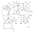
- Figure 1 shows a superconductive electrical network 10 which includes an electrical system and a cryogenic system, the operation of which are monitored by a controller 12.
- the electrical network 10 described in this embodiment is part of an aircraft which utilises so-called distributed propulsion in which a plurality of electrically driven propulsive units are distributed about the airframe.
- the invention is not limited to this application and can be implemented on any superconducting electrical network.
- the electrical system includes a plurality of pieces of superconducting electrical equipment.
- the superconducting electrical equipment includes superconducting generators, superconducting motors, refrigeration units, power electronic units in the form of convertors which are used to control the frequency and voltage within the network, and various electrical buses and wiring looms which include superconducting cables for example.
- superconducting electrical equipment may embrace other items of equipment. Further, some of the equipment within the electrical system may not be superconducting. For example, the various electrical buses and wiring looms may or may not be superconducting. As will also be appreciated, the electrical system may include any number of ancillary equipment such as isolators and superconducting fault current limiters (not shown).
- the gas turbine engine 16 provides power to the electrical generators 14a, 14b via independent mechanical power off takes 18a, 18b which in practice may include a combination of gearboxes and shafts, although these are not shown here for the sake of clarity.
- Each generator feeds a bus bar 20a, 20b via an isolator 21a, 21b, which in turn is connected to various pieces of electrical equipment in the form of two superconducting motors 22a1, 22a2, 22b1, 22b2.
- the connection between the bus bars 20a, 20b and the motors 22a1, 22a2, 22b1, 22b2 is made via a power electronic convertor 24a1, 24a2, 24b1, 24b2 and electrical isolators 26a1, 26a2, 26b1, 26b2 which are all connected by electrical cables.
- the bus bars 20a, 20b, and thus electrical generators 14a, 14b, are connected via an isolatable link 28 which extends between the two buses 20a, 20b.
- the cryogenic system includes a plurality of refrigeration units 30a, 30b, 32a, 32b which maintain control the supply of a coolant to the various items of superconducting electrical equipment.
- Each generator 14a, 14b has a single dedicated refrigeration unit 30a, 30b and the electrical motors 22a1, 22a2, 22b1, 22b2 each share a refrigeration unit 32a, 32b with one other motor 22a1, 22a2, 22b1, 22b2.
- the number and distribution of the refrigeration units will be determined by the type and distribution of the electrical equipment, which is in turn determined by the application of the electrical network.
- Each refrigeration unit 30a, 30b, 32a, 32b is connected to its respective piece or pieces of electrical equipment via a coolant pathway in the form of a primary conduit.
- a secondary conduits which connect at least one other refrigeration unit 30a, 30b, 32a, 32b to each piece of electrical equipment.
- electrical generator 14a is connected to refrigeration unit 30a via primary conduit 34a, and secondary conduit 34b.
- there is a network of coolant conduits 34a, 34b which can be configured to provide each piece of cooling equipment with an alternative supply of coolant.
- the superconductor material used for each element can be any known to date which is suitable for the purpose described above.
- the coolant can be any which is suitable for use with the chosen superconductor.
- Typical superconductors which would find utilisation would be Bismuth Strontium Calcium Copper Oxide (BSCCO), Yttrium Barium Copper Oxide (YBCO) or Magnesium Diboride (MgB 2 ) which would be cooled by liquid helium or hydrogen, or, in the case of BSCCO and YBCO, liquid nitrogen.
- the controller 12 is connected to each piece of electrical equipment and the gas turbine engine 16 (although only a few of these connections are shown in Figure 1 for the sake of clarity) and is configured to monitor the operating condition of each of the pieces of equipment such that it can determine the overall condition of the network 10.
- the condition may be in terms of the required and delivered distributed propulsive output and the power input. Alternatively, the condition may relate to the operating condition or health of each piece of equipment individually.
- the monitoring of the operating condition will involve the use of detection equipment, for example sensors, within the equipment or at selected locations throughout the electrical network. These sensors may include voltage, current or power meters, speed sensors or temperature sensors.
- the controller 12 may also be connected to the cryogenic system and monitor its operating condition so as to determine whether the coolant is being delivered as required for maintaining a superconducting state in each of the pieces of electrical equipment. In this way, if one of the refrigeration units begins to malfunction, it can be isolated and the supply provided from an alternative refrigeration unit, or the piece of electrical equipment which receives the affected coolant flow, isolated.
- the controller 12 monitors the condition of the electrical network and determines whether it is within predetermined limits which represent satisfactory operation. If a piece of equipment develops a fault and operates outside of the acceptable predetermined limits, it may be necessary for it to be isolated and another piece of electrical equipment to be operated at a higher level in order to make up for the shortfall created by the fault.
- a higher level it is meant that the electrical equipment may be operated at a higher power output and subjected to higher current flows, higher frequencies or higher switching frequencies, as appropriate for a given piece of equipment.
- other associated motors could be driven at higher speeds by increasing the electrical frequency supplied by power electronics, or by increasing the frequency supplied by the generator by increasing the rotational speed of the prime mover.
- the fault can be within a piece of electrical equipment or within the electrical distribution network which means that power can no longer be supplied with that required by the system.
- the fault can be within a piece of electrical equipment or within the electrical distribution network which means that power can no longer be supplied with that required by the system.
- a fault developed in the line at point 36 then it may be necessary to isolate that section of line, thereby making the electrical motor redundant even though it may not have a fault.
- a fault occurs in one of the refrigeration units and so affects the ability of a piece of electrical equipment to operate which results in it being shut down.
- the flow of coolant can be diverted from the isolated equipment to the remaining non-isolated equipment which can then be driven using higher current densities than the normal rated values and at which it would not normally be efficient to run at.
Landscapes
- Engineering & Computer Science (AREA)
- General Engineering & Computer Science (AREA)
- General Life Sciences & Earth Sciences (AREA)
- Mining & Mineral Resources (AREA)
- Paleontology (AREA)
- Civil Engineering (AREA)
- Life Sciences & Earth Sciences (AREA)
- Structural Engineering (AREA)
- Chemical & Material Sciences (AREA)
- Combustion & Propulsion (AREA)
- Mechanical Engineering (AREA)
- Aviation & Aerospace Engineering (AREA)
- Superconductive Dynamoelectric Machines (AREA)
- Superconductors And Manufacturing Methods Therefor (AREA)
- Control Of Eletrric Generators (AREA)
Applications Claiming Priority (1)
| Application Number | Priority Date | Filing Date | Title |
|---|---|---|---|
| GBGB1116759.0A GB201116759D0 (en) | 2011-09-29 | 2011-09-29 | A superconducting electrical system |
Publications (2)
| Publication Number | Publication Date |
|---|---|
| EP2575227A1 true EP2575227A1 (de) | 2013-04-03 |
| EP2575227B1 EP2575227B1 (de) | 2015-11-25 |
Family
ID=44994152
Family Applications (1)
| Application Number | Title | Priority Date | Filing Date |
|---|---|---|---|
| EP12185593.6A Active EP2575227B1 (de) | 2011-09-29 | 2012-09-24 | Supraleitendes elektrisches System |
Country Status (3)
| Country | Link |
|---|---|
| US (1) | US9321538B2 (de) |
| EP (1) | EP2575227B1 (de) |
| GB (1) | GB201116759D0 (de) |
Cited By (2)
| Publication number | Priority date | Publication date | Assignee | Title |
|---|---|---|---|---|
| GB2544052A (en) * | 2015-11-03 | 2017-05-10 | Rolls Royce Plc | Cooling system for electrical equipment |
| US20230080053A1 (en) * | 2021-09-10 | 2023-03-16 | Hamilton Sundstrand Corporation | Cryogenic fluid heat exchanger system for an aircraft environmental control system (ecs) |
Families Citing this family (5)
| Publication number | Priority date | Publication date | Assignee | Title |
|---|---|---|---|---|
| DE102015215130A1 (de) * | 2015-08-07 | 2017-02-09 | Siemens Aktiengesellschaft | Antriebssystem und Verfahren zum Antreiben eines Vortriebsmittels eines Fahrzeugs |
| DE102017223803A1 (de) * | 2017-12-27 | 2019-06-27 | Siemens Aktiengesellschaft | Elektrisches Antriebssystem, Fahrzeug und Verfahren zum Antrieb eines Fahrzeugs |
| GB201807769D0 (en) * | 2018-05-14 | 2018-06-27 | Rolls Royce Plc | Electric ducted fan |
| GB201807770D0 (en) * | 2018-05-14 | 2018-06-27 | Rolls Royce Plc | Electric ducted fan |
| US12162619B2 (en) | 2022-02-11 | 2024-12-10 | Rtx Corporation | Powertrain system of an aircraft including cyrogenic cooling loop for superconducting electronics and method of operating the same |
Citations (4)
| Publication number | Priority date | Publication date | Assignee | Title |
|---|---|---|---|---|
| EP0957026A2 (de) * | 1998-05-15 | 1999-11-17 | dbb fuel cell engines GmbH | Energieversorgungseinheit an Bord eines Luftfahrzeugs |
| EP1914162A1 (de) * | 2006-10-16 | 2008-04-23 | Converteam Ltd | DC Stromverteilungssystem |
| US20080191561A1 (en) * | 2007-02-09 | 2008-08-14 | Folts Douglas C | Parallel connected hts utility device and method of using same |
| US20110177954A1 (en) * | 2010-01-20 | 2011-07-21 | American Superconductor Corporation | Superconducting electricity transmission system |
Family Cites Families (3)
| Publication number | Priority date | Publication date | Assignee | Title |
|---|---|---|---|---|
| US3646243A (en) | 1969-10-27 | 1972-02-29 | Simplex Wire & Cable Co | Coolant circuit for resistive cryogenic electric power transmission line |
| JP4092728B2 (ja) * | 2005-01-25 | 2008-05-28 | 独立行政法人 宇宙航空研究開発機構 | 航空機用推進システム |
| US7434765B2 (en) * | 2005-02-16 | 2008-10-14 | The Boeing Company | Heat exchanger systems and associated systems and methods for cooling aircraft starter/generators |
-
2011
- 2011-09-29 GB GBGB1116759.0A patent/GB201116759D0/en not_active Ceased
-
2012
- 2012-09-24 US US13/625,490 patent/US9321538B2/en active Active
- 2012-09-24 EP EP12185593.6A patent/EP2575227B1/de active Active
Patent Citations (4)
| Publication number | Priority date | Publication date | Assignee | Title |
|---|---|---|---|---|
| EP0957026A2 (de) * | 1998-05-15 | 1999-11-17 | dbb fuel cell engines GmbH | Energieversorgungseinheit an Bord eines Luftfahrzeugs |
| EP1914162A1 (de) * | 2006-10-16 | 2008-04-23 | Converteam Ltd | DC Stromverteilungssystem |
| US20080191561A1 (en) * | 2007-02-09 | 2008-08-14 | Folts Douglas C | Parallel connected hts utility device and method of using same |
| US20110177954A1 (en) * | 2010-01-20 | 2011-07-21 | American Superconductor Corporation | Superconducting electricity transmission system |
Cited By (4)
| Publication number | Priority date | Publication date | Assignee | Title |
|---|---|---|---|---|
| GB2544052A (en) * | 2015-11-03 | 2017-05-10 | Rolls Royce Plc | Cooling system for electrical equipment |
| US10485145B2 (en) | 2015-11-03 | 2019-11-19 | Rolls-Royce Plc | Cooling system for electrical equipment |
| GB2544052B (en) * | 2015-11-03 | 2020-01-15 | Rolls Royce Plc | Cooling system for electrical equipment |
| US20230080053A1 (en) * | 2021-09-10 | 2023-03-16 | Hamilton Sundstrand Corporation | Cryogenic fluid heat exchanger system for an aircraft environmental control system (ecs) |
Also Published As
| Publication number | Publication date |
|---|---|
| US20130082518A1 (en) | 2013-04-04 |
| US9321538B2 (en) | 2016-04-26 |
| EP2575227B1 (de) | 2015-11-25 |
| GB201116759D0 (en) | 2011-11-09 |
Similar Documents
| Publication | Publication Date | Title |
|---|---|---|
| US9321538B2 (en) | Superconducting electrical system | |
| Rosero et al. | Moving towards a more electric aircraft | |
| US12597779B2 (en) | Aircraft electrical energy supply network | |
| US12097965B2 (en) | Electric architecture for a hybrid thermal/electric propulsion aircraft and twin-engined aircraft comprising such an architecture | |
| Abdel-Hafez | Power generation and distribution system for a more electric aircraft-a review | |
| US7952316B2 (en) | Variable frequency reduced speed variation electric drive | |
| US9394084B1 (en) | Aircraft electrical system operating method | |
| KR101405874B1 (ko) | 특히 동적으로 포지셔닝되는 선박들에서 발전기들과 추진기들을 연결시키기 위한 전기 스위치기어 | |
| KR20090076819A (ko) | 선박용 전력 분배 및 추진 시스템 | |
| US11828186B2 (en) | Electrical power systems | |
| Shekhar et al. | DC microgrid islands on ships | |
| Armstrong et al. | Trade studies for NASA N3-X turboelectric distributed propulsion system electrical power system architecture | |
| CN103298692A (zh) | 船舶推进系统 | |
| US20210403135A1 (en) | Power supply system for a water-bound device | |
| EP3322057B1 (de) | In verschiedene schutzzonen getrenntes gleichstromsystem | |
| US20210376602A1 (en) | Power supply system for a water-bound device that has different connected zones | |
| EP3209556A1 (de) | Energiesystem eines schwimmenden wasserfahrzeugs | |
| US11628943B2 (en) | Electrical power systems | |
| Radan et al. | Optimization of load dependent start tables in marine power management systems with blackout prevention | |
| CN111794913B (zh) | 超导风力涡轮发电机的自动斜变和能量释放的系统和方法 | |
| EP3070787A1 (de) | Abschlusseinheit | |
| US20190176951A1 (en) | Hybrid electrical and mechanical propulsion and energy system for a ship | |
| Oyori et al. | System design for the more electric engine incorporated in the electrical power management for more electric aircraft | |
| KR102327575B1 (ko) | 선박용 하이브리드 전기기계식 추진 및 에너지 시스템 | |
| US12202615B2 (en) | Electrical power systems |
Legal Events
| Date | Code | Title | Description |
|---|---|---|---|
| PUAI | Public reference made under article 153(3) epc to a published international application that has entered the european phase |
Free format text: ORIGINAL CODE: 0009012 |
|
| AK | Designated contracting states |
Kind code of ref document: A1 Designated state(s): AL AT BE BG CH CY CZ DE DK EE ES FI FR GB GR HR HU IE IS IT LI LT LU LV MC MK MT NL NO PL PT RO RS SE SI SK SM TR |
|
| AX | Request for extension of the european patent |
Extension state: BA ME |
|
| 17P | Request for examination filed |
Effective date: 20131003 |
|
| RBV | Designated contracting states (corrected) |
Designated state(s): AL AT BE BG CH CY CZ DE DK EE ES FI FR GB GR HR HU IE IS IT LI LT LU LV MC MK MT NL NO PL PT RO RS SE SI SK SM TR |
|
| RAP1 | Party data changed (applicant data changed or rights of an application transferred) |
Owner name: ROLLS-ROYCE PLC |
|
| GRAP | Despatch of communication of intention to grant a patent |
Free format text: ORIGINAL CODE: EPIDOSNIGR1 |
|
| GRAS | Grant fee paid |
Free format text: ORIGINAL CODE: EPIDOSNIGR3 |
|
| INTG | Intention to grant announced |
Effective date: 20150910 |
|
| GRAP | Despatch of communication of intention to grant a patent |
Free format text: ORIGINAL CODE: EPIDOSNIGR1 |
|
| GRAA | (expected) grant |
Free format text: ORIGINAL CODE: 0009210 |
|
| INTG | Intention to grant announced |
Effective date: 20151009 |
|
| AK | Designated contracting states |
Kind code of ref document: B1 Designated state(s): AL AT BE BG CH CY CZ DE DK EE ES FI FR GB GR HR HU IE IS IT LI LT LU LV MC MK MT NL NO PL PT RO RS SE SI SK SM TR |
|
| REG | Reference to a national code |
Ref country code: GB Ref legal event code: FG4D |
|
| REG | Reference to a national code |
Ref country code: CH Ref legal event code: EP |
|
| REG | Reference to a national code |
Ref country code: AT Ref legal event code: REF Ref document number: 763036 Country of ref document: AT Kind code of ref document: T Effective date: 20151215 |
|
| REG | Reference to a national code |
Ref country code: IE Ref legal event code: FG4D |
|
| REG | Reference to a national code |
Ref country code: DE Ref legal event code: R096 Ref document number: 602012012576 Country of ref document: DE |
|
| REG | Reference to a national code |
Ref country code: LT Ref legal event code: MG4D |
|
| REG | Reference to a national code |
Ref country code: NL Ref legal event code: MP Effective date: 20160225 |
|
| REG | Reference to a national code |
Ref country code: AT Ref legal event code: MK05 Ref document number: 763036 Country of ref document: AT Kind code of ref document: T Effective date: 20151125 |
|
| PG25 | Lapsed in a contracting state [announced via postgrant information from national office to epo] |
Ref country code: IS Free format text: LAPSE BECAUSE OF FAILURE TO SUBMIT A TRANSLATION OF THE DESCRIPTION OR TO PAY THE FEE WITHIN THE PRESCRIBED TIME-LIMIT Effective date: 20160325 Ref country code: NO Free format text: LAPSE BECAUSE OF FAILURE TO SUBMIT A TRANSLATION OF THE DESCRIPTION OR TO PAY THE FEE WITHIN THE PRESCRIBED TIME-LIMIT Effective date: 20160225 Ref country code: HR Free format text: LAPSE BECAUSE OF FAILURE TO SUBMIT A TRANSLATION OF THE DESCRIPTION OR TO PAY THE FEE WITHIN THE PRESCRIBED TIME-LIMIT Effective date: 20151125 Ref country code: LT Free format text: LAPSE BECAUSE OF FAILURE TO SUBMIT A TRANSLATION OF THE DESCRIPTION OR TO PAY THE FEE WITHIN THE PRESCRIBED TIME-LIMIT Effective date: 20151125 Ref country code: ES Free format text: LAPSE BECAUSE OF FAILURE TO SUBMIT A TRANSLATION OF THE DESCRIPTION OR TO PAY THE FEE WITHIN THE PRESCRIBED TIME-LIMIT Effective date: 20151125 Ref country code: NL Free format text: LAPSE BECAUSE OF FAILURE TO SUBMIT A TRANSLATION OF THE DESCRIPTION OR TO PAY THE FEE WITHIN THE PRESCRIBED TIME-LIMIT Effective date: 20151125 |
|
| REG | Reference to a national code |
Ref country code: DE Ref legal event code: R082 Ref document number: 602012012576 Country of ref document: DE Representative=s name: HERNANDEZ, YORCK, DIPL.-ING., DE |
|
| PG25 | Lapsed in a contracting state [announced via postgrant information from national office to epo] |
Ref country code: RS Free format text: LAPSE BECAUSE OF FAILURE TO SUBMIT A TRANSLATION OF THE DESCRIPTION OR TO PAY THE FEE WITHIN THE PRESCRIBED TIME-LIMIT Effective date: 20151125 Ref country code: PL Free format text: LAPSE BECAUSE OF FAILURE TO SUBMIT A TRANSLATION OF THE DESCRIPTION OR TO PAY THE FEE WITHIN THE PRESCRIBED TIME-LIMIT Effective date: 20151125 Ref country code: AT Free format text: LAPSE BECAUSE OF FAILURE TO SUBMIT A TRANSLATION OF THE DESCRIPTION OR TO PAY THE FEE WITHIN THE PRESCRIBED TIME-LIMIT Effective date: 20151125 Ref country code: GR Free format text: LAPSE BECAUSE OF FAILURE TO SUBMIT A TRANSLATION OF THE DESCRIPTION OR TO PAY THE FEE WITHIN THE PRESCRIBED TIME-LIMIT Effective date: 20160226 Ref country code: FI Free format text: LAPSE BECAUSE OF FAILURE TO SUBMIT A TRANSLATION OF THE DESCRIPTION OR TO PAY THE FEE WITHIN THE PRESCRIBED TIME-LIMIT Effective date: 20151125 Ref country code: SE Free format text: LAPSE BECAUSE OF FAILURE TO SUBMIT A TRANSLATION OF THE DESCRIPTION OR TO PAY THE FEE WITHIN THE PRESCRIBED TIME-LIMIT Effective date: 20151125 Ref country code: PT Free format text: LAPSE BECAUSE OF FAILURE TO SUBMIT A TRANSLATION OF THE DESCRIPTION OR TO PAY THE FEE WITHIN THE PRESCRIBED TIME-LIMIT Effective date: 20160325 Ref country code: LV Free format text: LAPSE BECAUSE OF FAILURE TO SUBMIT A TRANSLATION OF THE DESCRIPTION OR TO PAY THE FEE WITHIN THE PRESCRIBED TIME-LIMIT Effective date: 20151125 |
|
| PG25 | Lapsed in a contracting state [announced via postgrant information from national office to epo] |
Ref country code: CZ Free format text: LAPSE BECAUSE OF FAILURE TO SUBMIT A TRANSLATION OF THE DESCRIPTION OR TO PAY THE FEE WITHIN THE PRESCRIBED TIME-LIMIT Effective date: 20151125 Ref country code: IT Free format text: LAPSE BECAUSE OF FAILURE TO SUBMIT A TRANSLATION OF THE DESCRIPTION OR TO PAY THE FEE WITHIN THE PRESCRIBED TIME-LIMIT Effective date: 20151125 |
|
| REG | Reference to a national code |
Ref country code: DE Ref legal event code: R097 Ref document number: 602012012576 Country of ref document: DE |
|
| PG25 | Lapsed in a contracting state [announced via postgrant information from national office to epo] |
Ref country code: EE Free format text: LAPSE BECAUSE OF FAILURE TO SUBMIT A TRANSLATION OF THE DESCRIPTION OR TO PAY THE FEE WITHIN THE PRESCRIBED TIME-LIMIT Effective date: 20151125 Ref country code: SK Free format text: LAPSE BECAUSE OF FAILURE TO SUBMIT A TRANSLATION OF THE DESCRIPTION OR TO PAY THE FEE WITHIN THE PRESCRIBED TIME-LIMIT Effective date: 20151125 Ref country code: SM Free format text: LAPSE BECAUSE OF FAILURE TO SUBMIT A TRANSLATION OF THE DESCRIPTION OR TO PAY THE FEE WITHIN THE PRESCRIBED TIME-LIMIT Effective date: 20151125 Ref country code: DK Free format text: LAPSE BECAUSE OF FAILURE TO SUBMIT A TRANSLATION OF THE DESCRIPTION OR TO PAY THE FEE WITHIN THE PRESCRIBED TIME-LIMIT Effective date: 20151125 Ref country code: RO Free format text: LAPSE BECAUSE OF FAILURE TO SUBMIT A TRANSLATION OF THE DESCRIPTION OR TO PAY THE FEE WITHIN THE PRESCRIBED TIME-LIMIT Effective date: 20151125 |
|
| REG | Reference to a national code |
Ref country code: FR Ref legal event code: PLFP Year of fee payment: 5 |
|
| PLBE | No opposition filed within time limit |
Free format text: ORIGINAL CODE: 0009261 |
|
| STAA | Information on the status of an ep patent application or granted ep patent |
Free format text: STATUS: NO OPPOSITION FILED WITHIN TIME LIMIT |
|
| 26N | No opposition filed |
Effective date: 20160826 |
|
| PG25 | Lapsed in a contracting state [announced via postgrant information from national office to epo] |
Ref country code: SI Free format text: LAPSE BECAUSE OF FAILURE TO SUBMIT A TRANSLATION OF THE DESCRIPTION OR TO PAY THE FEE WITHIN THE PRESCRIBED TIME-LIMIT Effective date: 20151125 |
|
| PG25 | Lapsed in a contracting state [announced via postgrant information from national office to epo] |
Ref country code: BE Free format text: LAPSE BECAUSE OF FAILURE TO SUBMIT A TRANSLATION OF THE DESCRIPTION OR TO PAY THE FEE WITHIN THE PRESCRIBED TIME-LIMIT Effective date: 20151125 |
|
| PG25 | Lapsed in a contracting state [announced via postgrant information from national office to epo] |
Ref country code: MC Free format text: LAPSE BECAUSE OF FAILURE TO SUBMIT A TRANSLATION OF THE DESCRIPTION OR TO PAY THE FEE WITHIN THE PRESCRIBED TIME-LIMIT Effective date: 20151125 |
|
| REG | Reference to a national code |
Ref country code: CH Ref legal event code: PL |
|
| REG | Reference to a national code |
Ref country code: IE Ref legal event code: MM4A |
|
| PG25 | Lapsed in a contracting state [announced via postgrant information from national office to epo] |
Ref country code: IE Free format text: LAPSE BECAUSE OF NON-PAYMENT OF DUE FEES Effective date: 20160924 Ref country code: CH Free format text: LAPSE BECAUSE OF NON-PAYMENT OF DUE FEES Effective date: 20160930 Ref country code: LI Free format text: LAPSE BECAUSE OF NON-PAYMENT OF DUE FEES Effective date: 20160930 |
|
| PG25 | Lapsed in a contracting state [announced via postgrant information from national office to epo] |
Ref country code: LU Free format text: LAPSE BECAUSE OF NON-PAYMENT OF DUE FEES Effective date: 20160924 |
|
| REG | Reference to a national code |
Ref country code: FR Ref legal event code: PLFP Year of fee payment: 6 |
|
| PG25 | Lapsed in a contracting state [announced via postgrant information from national office to epo] |
Ref country code: HU Free format text: LAPSE BECAUSE OF FAILURE TO SUBMIT A TRANSLATION OF THE DESCRIPTION OR TO PAY THE FEE WITHIN THE PRESCRIBED TIME-LIMIT; INVALID AB INITIO Effective date: 20120924 Ref country code: CY Free format text: LAPSE BECAUSE OF FAILURE TO SUBMIT A TRANSLATION OF THE DESCRIPTION OR TO PAY THE FEE WITHIN THE PRESCRIBED TIME-LIMIT Effective date: 20151125 |
|
| PG25 | Lapsed in a contracting state [announced via postgrant information from national office to epo] |
Ref country code: TR Free format text: LAPSE BECAUSE OF FAILURE TO SUBMIT A TRANSLATION OF THE DESCRIPTION OR TO PAY THE FEE WITHIN THE PRESCRIBED TIME-LIMIT Effective date: 20151125 Ref country code: MT Free format text: LAPSE BECAUSE OF NON-PAYMENT OF DUE FEES Effective date: 20160930 Ref country code: MK Free format text: LAPSE BECAUSE OF FAILURE TO SUBMIT A TRANSLATION OF THE DESCRIPTION OR TO PAY THE FEE WITHIN THE PRESCRIBED TIME-LIMIT Effective date: 20151125 |
|
| PG25 | Lapsed in a contracting state [announced via postgrant information from national office to epo] |
Ref country code: BG Free format text: LAPSE BECAUSE OF FAILURE TO SUBMIT A TRANSLATION OF THE DESCRIPTION OR TO PAY THE FEE WITHIN THE PRESCRIBED TIME-LIMIT Effective date: 20151125 |
|
| REG | Reference to a national code |
Ref country code: FR Ref legal event code: PLFP Year of fee payment: 7 |
|
| PG25 | Lapsed in a contracting state [announced via postgrant information from national office to epo] |
Ref country code: AL Free format text: LAPSE BECAUSE OF FAILURE TO SUBMIT A TRANSLATION OF THE DESCRIPTION OR TO PAY THE FEE WITHIN THE PRESCRIBED TIME-LIMIT Effective date: 20151125 |
|
| P01 | Opt-out of the competence of the unified patent court (upc) registered |
Effective date: 20230528 |
|
| PGFP | Annual fee paid to national office [announced via postgrant information from national office to epo] |
Ref country code: DE Payment date: 20250926 Year of fee payment: 14 |
|
| PGFP | Annual fee paid to national office [announced via postgrant information from national office to epo] |
Ref country code: GB Payment date: 20250923 Year of fee payment: 14 |
|
| PGFP | Annual fee paid to national office [announced via postgrant information from national office to epo] |
Ref country code: FR Payment date: 20250925 Year of fee payment: 14 |