EP2575311A1 - Demodulationsvorrichtung - Google Patents
Demodulationsvorrichtung Download PDFInfo
- Publication number
- EP2575311A1 EP2575311A1 EP12184889A EP12184889A EP2575311A1 EP 2575311 A1 EP2575311 A1 EP 2575311A1 EP 12184889 A EP12184889 A EP 12184889A EP 12184889 A EP12184889 A EP 12184889A EP 2575311 A1 EP2575311 A1 EP 2575311A1
- Authority
- EP
- European Patent Office
- Prior art keywords
- signal
- phase
- frequency
- sad
- microwave
- Prior art date
- Legal status (The legal status is an assumption and is not a legal conclusion. Google has not performed a legal analysis and makes no representation as to the accuracy of the status listed.)
- Granted
Links
- 230000010363 phase shift Effects 0.000 claims abstract description 17
- 230000003287 optical effect Effects 0.000 claims description 61
- 230000005540 biological transmission Effects 0.000 claims description 25
- 230000005693 optoelectronics Effects 0.000 claims description 13
- 238000005070 sampling Methods 0.000 claims description 11
- 239000013307 optical fiber Substances 0.000 claims description 10
- 230000008901 benefit Effects 0.000 description 10
- 238000004458 analytical method Methods 0.000 description 7
- 238000000034 method Methods 0.000 description 7
- 230000006870 function Effects 0.000 description 6
- 238000000926 separation method Methods 0.000 description 6
- 238000010276 construction Methods 0.000 description 5
- 230000006641 stabilisation Effects 0.000 description 5
- 239000000835 fiber Substances 0.000 description 4
- 238000011105 stabilization Methods 0.000 description 4
- 230000001934 delay Effects 0.000 description 3
- 230000003111 delayed effect Effects 0.000 description 3
- 238000001514 detection method Methods 0.000 description 3
- 238000001914 filtration Methods 0.000 description 3
- 230000006798 recombination Effects 0.000 description 3
- 238000005215 recombination Methods 0.000 description 3
- 230000035945 sensitivity Effects 0.000 description 3
- 230000009466 transformation Effects 0.000 description 3
- 229910052691 Erbium Inorganic materials 0.000 description 2
- 238000006243 chemical reaction Methods 0.000 description 2
- 235000021183 entrée Nutrition 0.000 description 2
- UYAHIZSMUZPPFV-UHFFFAOYSA-N erbium Chemical compound [Er] UYAHIZSMUZPPFV-UHFFFAOYSA-N 0.000 description 2
- 230000033001 locomotion Effects 0.000 description 2
- 238000005259 measurement Methods 0.000 description 2
- 238000011144 upstream manufacturing Methods 0.000 description 2
- 229910003327 LiNbO3 Inorganic materials 0.000 description 1
- 241001632004 Tetrahymena sp. SIN Species 0.000 description 1
- 230000008859 change Effects 0.000 description 1
- 239000013078 crystal Substances 0.000 description 1
- 230000007547 defect Effects 0.000 description 1
- 230000001627 detrimental effect Effects 0.000 description 1
- 239000006185 dispersion Substances 0.000 description 1
- 230000007274 generation of a signal involved in cell-cell signaling Effects 0.000 description 1
- 238000012423 maintenance Methods 0.000 description 1
- 230000008569 process Effects 0.000 description 1
- 230000004044 response Effects 0.000 description 1
- 230000009131 signaling function Effects 0.000 description 1
- 230000000087 stabilizing effect Effects 0.000 description 1
- 230000001131 transforming effect Effects 0.000 description 1
- 238000011282 treatment Methods 0.000 description 1
Images

Classifications
-
- H—ELECTRICITY
- H04—ELECTRIC COMMUNICATION TECHNIQUE
- H04L—TRANSMISSION OF DIGITAL INFORMATION, e.g. TELEGRAPHIC COMMUNICATION
- H04L27/00—Modulated-carrier systems
- H04L27/0014—Carrier regulation
-
- H—ELECTRICITY
- H03—ELECTRONIC CIRCUITRY
- H03D—DEMODULATION OR TRANSFERENCE OF MODULATION FROM ONE CARRIER TO ANOTHER
- H03D1/00—Demodulation of amplitude-modulated oscillations
- H03D1/22—Homodyne or synchrodyne circuits
- H03D1/2245—Homodyne or synchrodyne circuits using two quadrature channels
- H03D1/2254—Homodyne or synchrodyne circuits using two quadrature channels and a phase locked loop
-
- H—ELECTRICITY
- H03—ELECTRONIC CIRCUITRY
- H03B—GENERATION OF OSCILLATIONS, DIRECTLY OR BY FREQUENCY-CHANGING, BY CIRCUITS EMPLOYING ACTIVE ELEMENTS WHICH OPERATE IN A NON-SWITCHING MANNER; GENERATION OF NOISE BY SUCH CIRCUITS
- H03B2200/00—Indexing scheme relating to details of oscillators covered by H03B
- H03B2200/006—Functional aspects of oscillators
- H03B2200/0078—Functional aspects of oscillators generating or using signals in quadrature
-
- H—ELECTRICITY
- H04—ELECTRIC COMMUNICATION TECHNIQUE
- H04L—TRANSMISSION OF DIGITAL INFORMATION, e.g. TELEGRAPHIC COMMUNICATION
- H04L27/00—Modulated-carrier systems
- H04L27/0014—Carrier regulation
- H04L2027/0044—Control loops for carrier regulation
- H04L2027/0053—Closed loops
- H04L2027/0057—Closed loops quadrature phase
Definitions
- the invention relates to a signal demodulation device. It applies for example to the demodulation of radar signals, the demodulation of lidar-radar signals and the demodulation of QAM coded signals (telecommunication, television). More particularly, the invention relates to a device for demodulating a microwave signal using I / Q type demodulation.
- a demodulation of a frequency signal f belonging to the microwave domain makes it possible to determine the amplitude and / or the phase (or a combination of both) of the frequency signal f.
- f is a reference frequency. This is not necessarily the center frequency of the signal S (t).
- the center frequency of S (t) is f + d / dt ( ⁇ (t)).
- Demodulating this signal S (t) means determining its amplitude A (t) and its phase ⁇ (t), or equivalently its amplitude in phase I (t) and its amplitude in quadrature Q (t).
- I / Q demodulation In-phase and quadrature demodulation (commonly known as I / Q demodulation) which provides the I (t) and Q (t) values directly.
- the signal S (t) is multiplied on the one hand by cos (2 ⁇ ft) and on the other hand by sin (2 ⁇ ft), then a low frequency filtering is performed.
- I (t) for the part of the signal S (t) which has been multiplied by the cosine
- Q (t) for the part of the signal S (t) which has been multiplied by the sinus.
- the main problem is to have both cos (2 ⁇ ft) and sin (2 ⁇ ft).
- the signal sin (2 ⁇ ft) is not available, and it is necessary to generate it from the signal cos (2 ⁇ ft).
- This step corresponds to a phase shift of ⁇ / 2.
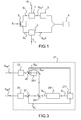
- the figure 1 describes such a device according to the state of the art using a ⁇ / 2 phase shifter.
- the signal S (t) is separated into two parts S1 (t) and S2 (t) by means of separation means 5.
- An oscillator 4 at the carrier frequency f generates the signal cos (2 ⁇ ft) and is separated into two parts.
- a first part is out of phase of ⁇ / 2 by the phase-shifter 3, thus forming the quadrature signal Sas1 in sin (2 ⁇ ft), which is multiplied by S1 (t) with the aid of a multiplier 1.
- the signal Q is obtained.
- the second part in cos (2 ⁇ ft) forms the signal in phase Sas2 which is multiplied by S2 (t) with the aid of a multiplier 2.
- the signal I is constituted.
- the usual microwave phase shifters generally make it possible to carry out the ⁇ / 2 phase shift for a frequency band around a predefined frequency f.
- the quadrature (+/- a few degrees) is then obtained over a narrow band, typically of the order of 10% around the frequency f.
- the quadrature is thus valid on a narrow band and is not very precise.
- the bandwidth problem can be improved by using a tunable phase shifter with phase control, as described for example in the document US5150128 .
- a tunable phase shifter with phase control as described for example in the document US5150128 .
- the bandwidth is quite small (typically a few tens of percent)
- they have high losses (typically 6 dB)
- their response time is slow ( typically the ⁇ s).
- the I / Q demodulation thus has an advantage over the frequency-shifted demodulation because it does not have these two constraints: it makes it possible to directly measure the two functions I (t) and Q (t) which define the signal S (t). ).
- the bandwidth required to analyze these two signals is therefore directly, for the signal I (t), the maximum frequency of (I (t) and for the signal Q (t), the maximum frequency of Q (t). unambiguously is valid regardless of the bandwidth of these signals.
- An object of the present invention is in particular to overcome the disadvantage of the above-mentioned I / Q demodulation using a phase-shifter, by proposing a device for demodulating a microwave signal in phase and in quadrature associated with a frequency-locked loop.
- This architecture makes it possible to guarantee a perfect quadrature whatever the type of phase-shifter and to guarantee the stability of the frequency f.
- a first aspect of the invention relates to a device for demodulating I / Q of a microwave signal using a microwave signal in phase and a microwave signal in quadrature, characterized in that said signals in phase and in quadrature are generated.
- a frequency-locked device comprising a frequency-tunable generator able to be controlled by a control signal, said generator delivering a frequency-controlled signal, at least a first phase-shifter introducing a phase shift on the slave signal and generating at the output of the phase shifter a phase shifted servo signal, said phase shift being a function of the frequency of the phase-shifted signal, a phase comparator comparing the phase of the slaved signal and the phase of the shifted servo signal and delivering an output signal depending on the difference between said phases, said output signal generating the control signal of said generator of so that the frequency of said generator is adapted so that the phase of the controlled signal and the phase of the phase-shifted servocontrol signal have a difference substantially equal to an odd multiple of ⁇
- This type of I / Q demodulation uses a frequency locked loop ("Frequency Locked Loop” or FLL) instead of a ⁇ / 2 phase-shifter and thus makes it possible to stabilize the carrier frequency f of the microwave signal.
- FLL Frequency Locked Loop
- Another advantage of certain embodiments is a feasible demodulation over a wide frequency interval f.
- the demodulation frequency is set on one of the stable positions of the frequency control. It can therefore have a frequency difference df with the received signal. This induces an increase in the analysis band exactly equal to df.
- df it is necessary for df to be less than the maximum between (max frequency of (I (t)) and (max frequency of Q (t)) .
- the slave signal is also out of phase by a second phase-shifter and the phase comparator compares the respective phases of the two out-of-phase servo signals.
- the phase shifter comprises a dispersive filter, which has a strong dependence of the frequency as a function of the phase, thus making it possible to obtain a more sensitive and precise device for determining the demodulated frequency.
- the phase shifter comprises a delay line, which is the simplest method for obtaining a strong dependence of the frequency as a function of the phase, ie a high sensitivity, while allowing the device to operate over a wide range frequency f.
- the phase shifter is obtained by optical means.
- the phase-shifter comprises an optical resonant filter.
- Optical filters can be very resonant and therefore very dispersive, that is to say they induce a strong dependence of the frequency according to the phase, and are generally very compact.
- the phase shifter comprises a delay line acting on the optical beam.
- the delay lines for example fiber optic, are very inexpensive, have few losses and are very compact (10 km delay is equivalent to 50% losses and can fit in one liter).
- the demodulation can be performed for a set of discrete frequencies which are distributed over a wide range and which are narrower than when the phase shift is performed directly on the microwave.
- the delay line is an optical fiber, which has little loss, is compact and low cost.
- the phase shifter comprises a laser generating an optical wave modulated at a frequency belonging to the microwave domain and a fast photodiode.
- the phase shift on one of the arms is thus achieved using optical means, the rest of the chain operating directly with the microwave signal, which allows the use of standard microwave components
- the tunable generator is a laser generating an optical wave modulated at a frequency belonging to the microwave domain.
- the phase shift can thus be generated optically and without electrical / optical conversion on the two parts of the slave signal intended to be recombined for the comparison of their respective phase.
- Optical electrical conversions consume a lot and are expensive.
- the slave signal and the phase-shifted servo signal are optical beams, part of which is taken by sampling means, each of said parts constituting an input of the phase comparator.
- each of said parts is optically recombined using a non-linear component whose function is to compare the phases.
- the phase comparison is performed optically and does not require an optoelectronic component for transforming the optical wave into a microwave and a microwave phase comparator, all the processing being carried out optically.
- the output signal of said component is transformed into an electrical control signal with the aid of an optoelectronic component.
- At least one of said parts is transformed into an electrical signal before the input of the phase comparator.
- the enslaved signal and the phase-shifted servocontrol signal are each transformed into a microwave electrical signal by means of an optoelectronic component in order to generate said optical waveform.
- in-phase and quadrature signals to perform the I / Q demodulation.
- the slave signal and the phase-shifted servocontrol signal are each transformed into a microwave electrical signal using an optoelectronic component, a part of which is taken by sampling means, each of said parts constituting an input of the phase comparator.
- a radar transmitting and receiving system comprising a transmission channel comprising a transmitting antenna, a receiving channel comprising a receiving antenna, a demodulation device as defined above, the transmission signal being derived from the slave signal and the reception signal generating the signal to be demodulated.
- a transmission and reception system for lidar comprising an optical wave transmission chain comprising a transmitting element, an optical wave receiving channel comprising a receiver element, a demodulation device in phase and quadrature as defined above, the optical transmission signal being derived from the slave signal, said slave signal being generated by a laser, the reception optical signal being converted into a microwave signal by a optoelectronic component before generating the signal to be demodulated.
- a transmission and reception system for lidar comprising an optical wave transmission chain comprising a transmitting element, an optical wave receiving channel comprising a receiver element, a demodulation device in phase and quadrature as defined above, the optical transmission signal being derived from the slave signal, said slave signal being generated by a laser, the reception optical signal being converted into a microwave signal by a optoelectronic component before generating the signal to be demodulated.
- the principle of a frequency lock loop (“FLL”) used in the invention is described on the figure 2 .
- the signal Sa delivered by a frequency-tunable generator 26 is separated into two parts generating two signals, of which one (or both) is independently phase-shifted relative to the other by means of a phase-shifter 25, by example by dispersion or delay. These two independently phase-shifted parts are then compared with the aid of a phase comparator 27, for example a microwave mixer.
- the comparator delivers a signal function of the difference of the two phases.
- the phase comparator is a microwave mixer, it delivers a voltage proportional to the cosine of the phase difference.
- the quadrature between the two signals corresponds to a certain value at the output of the comparator, for example 0 when the comparator is a mixer.
- the signal from the comparator is injected into the tunable generator in the form of a control signal Sc. of the generator can be enslaved so as to obtain the quadrature between the two channels.
- the advantage of this type of loop is that the maintenance of the quadrature corresponds to a stabilization of the transmitted frequency.
- the signal delivered by the generator is thus a signal Sa servocontrolled in frequency.
- the figure 2 illustrates the principle of operation of a device according to the invention.
- a tunable generator 26 generates a signal Sa, which is separated into two parts by separation means 24.
- the first part of the signal Sa is phase-shifted by a phase-shifter 25. With the output of the phase-shifter, a phase-shifted signal Sad is obtained. This phase-shifted signal is separated into two channels by sampling means 22. One channel is used as a first input Sad 'of a phase comparator 27, and the other channel is used for the generation of the quadrature signal Sas1 for the I / Q demodulation.
- the second part of the signal Sa is not out of phase and is also separated in two ways by sampling means 23.
- One channel is used as the second input Sa 'of the phase comparator 27.
- the phase comparator 27 compares the respective phases signals Sad 'and Sa' and delivers an output signal depending on the difference between these two phases.
- This output signal is used to generate the control signal Sc of the tunable generator 26, so that the frequency thereof is adjusted to obtain a phase difference equal to ⁇ / 2 between the signal Sad of one hand, and the signal Sa on the other hand.
- a servo-control loop of the frequency of the signal Sa delivered by the generator 26 is thus implemented, allowing simultaneously the stabilization of the frequency and the obtaining of two signals in quadrature, Sad and Sa.
- the other path is used to signal generation in Sas2 phase for I / Q demodulation.
- the signal in phase Sas2, coming from the generator, and the quadrature signal Sas1 obtained using the phase-shifter are generated by a device 21 incorporating a frequency-locked loop. They are then mixed with the signal S to be demodulated according to the classical principle of I / Q demodulation.
- the second portion of the slave signal is also phase shifted by a phase shifter not shown, generating a second phase-shifted signal.
- the phase comparator compares the phases ⁇ and ⁇ of the two phase-shifted servocontrolled signals in the same manner as previously described.
- the frequency-controlled generator is a microwave generator.
- the phase comparator may be a microwave mixer which delivers a voltage proportional to the cosine of the phase difference.
- the phase shifter is for example a dispersive filter or a delay line acting on the microwave signal.
- phase shifter When the phase shifter is a dispersive filter, a phase shift of ⁇ / 2 is obtained in the vicinity of a frequency f. Typically with a resonant microwave filter, a change in frequency f of more than 100 kHz is obtained when the phase shift is derived from ⁇ . This type of phase shifter thus allows a fine servocontrol on the frequency f.
- delays T ⁇ 100 ns can be obtained with the aid of long wired delays, hence an interval ⁇ f> 10 Mhz.
- the scanning of the frequency demodulation f is obtained by incrementing the quadratures, that is to say by varying the value of k relative integer by adjusting the value of the delay.
- Tightening the slave discrete frequencies is useful for demodulating signals whose center frequency is arbitrary. This makes it possible to perform I / Q demodulation with a signal controlled at a closer frequency.
- the phase shifter can be produced with a delay obtained by optical means.
- the phase shifter comprises, for example, a laser delivering an optical wave modulated by the microwave signal to be delayed, a phase shifter introducing the delay by acting on the optical wave, and an optoelectronic component such as a fast photodiode making it possible to carry out the transformation of the wave. optical in a microwave signal.
- the phase shifter comprises for example an optical fiber.
- an optical fiber With an optical fiber, a delay of 0.5 ⁇ s is obtained for a length of 100m of fiber.
- delays T of the order of 1 ms can be obtained from which an interval ⁇ f ⁇ 1 kHz.
- An advantage of the optical delay, with respect to a delay carried out directly on the microwave wave, is thus to tighten the interval of separation between two servo discrete frequencies.
- the other advantage is to take advantage of this long delay to achieve a better sensitivity FLL.
- the phase shifter comprises for example a resonant optical filter, for example a whispering gallery mode resonator.
- This type of phase shifter is very compact and very sensitive. Typically we obtain sensitivities to frequency drift equivalent to several kilometers of fiber with a Wispering Gallery Mode type component of a few millimeters in diameter.
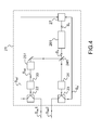
- the frequency-controlled signal is an optical signal generated by a laser 261, the optical wave being modulated at the frequency of the hyper signal, as described figure 3 .
- the optical signal is separated into two channels by means of separation means 241, and a phase shift is operated by a phase shifter 251 obtained by optical means, for example a resonant optical filter or an optical fiber as described above and having the same benefits.
- Sa ', Sad' part of the two optical signals Sa, Sad is taken by the sampling means 36, 37.
- the two parts constitute two channels, one formed by the optical signal Sa ', the other formed by the Sad 'optical signal, which recombine at the level of the phase comparator, which they are the two inputs.
- This recombination comparing the phases can be performed optically by a non-linear component, such as a crystal doubling frequency.
- the optical output signal is converted into an electrical control signal Sc for the laser by an optoelectronic component, typically comprising a photodiode.
- This recombination comparing the phases can also be performed in a hybrid manner, one of the channels being transformed into an electrical signal before entering the phase comparator.
- An example of a hybrid comparator is an optical amplitude modulator of Mach Zehnder type bundled with LiNbO3.
- This recombination comparing the phases can also be performed electrically using two optical / hyper transformation components.
- optical signals one from the phase shifter Sad, the other coming directly from the output signal of the laser Sa are each transformed into microwave electrical signals by means of optoelectronic components 33, 34 located downstream of the sampling means 36, 37, for use as in-phase and quadrature signals for I / Q demodulation.
- the optical beams obtained at the output of the laser Sa, and the phase shifter Sad are converted into microwave signals by means of optoelectronic components 33, 32 positioned upstream of the sampling means 22, 23.
- a Sa ', Sad' portion of these microwave signals Sa, Sad is taken by the sampling means 22, 23 for the phase comparison.
- the phase comparator 27 has according to this option two microwave electrical inputs.
- the phase comparator may be a microwave mixer which delivers a voltage proportional to the cosine of the phase difference.
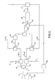
- the figure 5 presents a transmission / reception chain using a device as described above, integrated in a transmission / reception chain for radar application according to the invention.
- the chain comprises a transmission antenna 52 whose transmission signal is derived from the enslaved signal delivered by the generator, amplified by an amplifier 53.
- the emitted signal therefore has a frequency f equal to the frequency of the slave signal.
- the chain further comprises a receiving antenna 51 which receives a reflected signal (for example a target echo for example).
- This reception signal is amplified by an amplifier (not shown) before being separated into two parts by the separation means 5 in order to be analyzed by I / Q demodulation.
- the signals in the phase Sas2 and in quadrature Sas1 have the same frequency f as the signal to be analyzed.
- the advantage of such a system is to operate with a frequency stabilized at a value corresponding to obtaining quadrature signals for the I / Q demodulation.
- the system is broadband by construction.
- the transmission / reception device also applies to a transmission / reception chain for telecommunications.
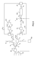
- the figure 6 presents a transmission / reception chain using a device as described above, integrated in a transmission / reception chain for lidar application according to the invention.
- the entire chain uses a modulated optical beam at a microwave carrier frequency.
- the chain comprises a transmission lens 62 whose transmission signal is derived from the enslaved signal delivered by the laser 261.
- the signal is amplified by an amplifier 63, for example an Erbium doped optical fiber amplifier.
- the transmission signal is therefore an optical signal modulated at the controlled frequency f.
- the chain further includes a receiving lens 61 which collects the reflected optical wave.
- This optical signal to be analyzed is transformed into a microwave signal by means of an electronic component 64 comprising for example a photodiode and an amplifier, before being separated into two parts by the separation means (5) in order to carry out its analysis. by I / Q demodulation
- the optical signal from the laser Sa is separated into two parts and the quadrature of the microwave modulation is performed by controlling the frequency as described above.
- This slaving can be carried out with, at the input of the comparator, two optical signals, an optical signal and a microwave electrical signal, or with two microwave signals.
- optoelectronic components 33, 34 of optical / hyper transformation are positioned upstream of the sampling means 22, 23 for the phase comparison.
- the resulting lidar transmit / receive chain enables very accurate detection of target motion by stabilizing the frequency coupled to broadband I / Q demodulation by construction.
- the laser 261 is a dual-frequency laser emitting at a wavelength of 1.5 ⁇ m. It emits an optical signal modulated in intensity at the frequency f, typically with a power of 30 mW.
- the hyperf frequency is adjustable by applying a voltage directly to an electro-optical element of the laser.
- the average frequency is adjusted by the temperature between 1 and 5GHz (1GHz per ° C).
- Fine tuning is performed using a voltage with a tuning coefficient of the order of 1 MHz / V.
- the hyper modulation frequency of such a laser is unstable, varying from several megahertz to a few seconds.
- a fraction of the signal from the laser is separated into two parts constituting two beams (about 2 mW each) by a beam splitter 241.
- the other fraction of the signal from the laser is directed via the separator 541 to the transmission lens.
- a part of the beam Sa is not out of phase and is detected directly by a photodiode 34.
- the other part of the beam is delayed by an optical fiber delay line, 100 m long, generating the Sad beam.
- T 0.5 ⁇ s or ⁇ f ⁇ 2 MHz.
- the beam is detected by a photodiode.
- the two microwave electrical signals thus obtained Sa and Sad are then amplified and then taken by the means 22, 23.
- the sampled portions Sa 'and Sad' are compared in phase with the aid of a microwave mixer 27.
- the stabilization obtained is better than ten kHz in a few seconds (compared to a few MHz without servocontrol).
- the parts of the microwave signals not sampled for phase comparison are used as quadrature signals Sas2 and in phase Sas1 for I / Q demodulation.
- the portion of the optical signal intended for transmission is amplified using an Erbium 63 doped optical fiber amplifier.
- Part of the backscattered signal is collected in an optical fiber and detected by a fast photodiode 64.
- the microwave signal obtained is by construction modulated at the frequency f, and the analysis of the movement of the target is performed by I / Q demodulation.
- the modulation of the signal is first detected and amplified.
- the signal S to be analyzed is then separated into two parts S1 and S2.
- the second part S2 is mixed via a mixer 2 to the part of the undelayed signal Sas2.
- the signal resulting from this mixing corresponds to the signal 1 of a conventional I / Q detection.
- the first part S1 is mixed via a mixer 1 to the part of the signal which has been delayed Sas1, the phase shift being by construction equal to ⁇ / 2.
- the resulting signal from this mixer corresponds to the Q signal of a conventional I / Q detection
Landscapes
- Engineering & Computer Science (AREA)
- Power Engineering (AREA)
- Computer Networks & Wireless Communication (AREA)
- Signal Processing (AREA)
- Optical Communication System (AREA)
- Optical Radar Systems And Details Thereof (AREA)
- Radar Systems Or Details Thereof (AREA)
Applications Claiming Priority (1)
| Application Number | Priority Date | Filing Date | Title |
|---|---|---|---|
| FR1102967A FR2980929B1 (fr) | 2011-09-30 | 2011-09-30 | Dispositif de demodulation de signaux |
Publications (2)
| Publication Number | Publication Date |
|---|---|
| EP2575311A1 true EP2575311A1 (de) | 2013-04-03 |
| EP2575311B1 EP2575311B1 (de) | 2018-03-28 |
Family
ID=46829674
Family Applications (1)
| Application Number | Title | Priority Date | Filing Date |
|---|---|---|---|
| EP12184889.9A Active EP2575311B1 (de) | 2011-09-30 | 2012-09-18 | System zur Demodulation |
Country Status (2)
| Country | Link |
|---|---|
| EP (1) | EP2575311B1 (de) |
| FR (1) | FR2980929B1 (de) |
Citations (3)
| Publication number | Priority date | Publication date | Assignee | Title |
|---|---|---|---|---|
| WO1988002196A1 (en) * | 1986-09-16 | 1988-03-24 | Plessey Overseas Limited | Quadrature signals generator |
| US5150128A (en) | 1991-02-15 | 1992-09-22 | Hughes Aircraft Company | In-phase and quadrature conversion error compensator |
| EP2019484A1 (de) * | 2007-07-24 | 2009-01-28 | GloNav Limited | Quadratur-VCO-System und -Verfahren |
-
2011
- 2011-09-30 FR FR1102967A patent/FR2980929B1/fr not_active Expired - Fee Related
-
2012
- 2012-09-18 EP EP12184889.9A patent/EP2575311B1/de active Active
Patent Citations (3)
| Publication number | Priority date | Publication date | Assignee | Title |
|---|---|---|---|---|
| WO1988002196A1 (en) * | 1986-09-16 | 1988-03-24 | Plessey Overseas Limited | Quadrature signals generator |
| US5150128A (en) | 1991-02-15 | 1992-09-22 | Hughes Aircraft Company | In-phase and quadrature conversion error compensator |
| EP2019484A1 (de) * | 2007-07-24 | 2009-01-28 | GloNav Limited | Quadratur-VCO-System und -Verfahren |
Non-Patent Citations (2)
| Title |
|---|
| NORIMATSU S ET AL: "An 8 Gb/s QPSK optical homodyne detection experiment using external-cavity laser diodes", IEEE PHOTONICS TECHNOLOGY LETTERS, IEEE SERVICE CENTER, PISCATAWAY, NJ, US, vol. 4, no. 7, 1 July 1992 (1992-07-01), pages 765 - 767, XP011410448, ISSN: 1041-1135, DOI: 10.1109/68.145266 * |
| OKAMOTO K ET AL: "Nearly Shot-Noise-Limited Performance of Dual-Channel Linear Optical Sampling for Ultrafast DPSK Signals", IEEE JOURNAL OF QUANTUM ELECTRONICS, IEEE SERVICE CENTER, PISCATAWAY, NJ, USA, vol. 45, no. 6, 1 June 2009 (2009-06-01), pages 711 - 719, XP011257363, ISSN: 0018-9197 * |
Also Published As
| Publication number | Publication date |
|---|---|
| FR2980929B1 (fr) | 2013-10-25 |
| EP2575311B1 (de) | 2018-03-28 |
| FR2980929A1 (fr) | 2013-04-05 |
Similar Documents
| Publication | Publication Date | Title |
|---|---|---|
| EP0120775B1 (de) | Entfernungs- und Dopplermessung mittels einer Laseranordnung mit Pulszeitraffung | |
| EP3714233B1 (de) | Vorrichtung und verfahren zur interaktion zwischen einem agilen laserstrahl und einem hyperfeinen energieübergang einer chemischen spezies | |
| US11262453B2 (en) | Separation of lidar channels from a common signal | |
| EP3520182B1 (de) | Lasersystem mit optischer rückkopplung | |
| EP4256291B1 (de) | Vorrichtung zur breitbandigen spektralanalyse eines signals | |
| FR2986379A1 (fr) | "laser accordable en phase continue" | |
| EP0561690B1 (de) | Verfahren und Vorrichtung zur Feststellung des Erreichens eines vorausbestimmten Abstandes eines Punktreflektors mittels der Laufzeit einer kontinuierlichen Welle | |
| EP2642659B1 (de) | Abstimmbarer optoelektronischer Oszillator mit schwachem Phasenrauschen | |
| FR2680248A1 (fr) | Procede et systeme de mesure de signaux electrique a haute frequence par effet electro-optique. | |
| WO2012038662A1 (fr) | Mesure telemetrique utilisant un dispositif de type lidar a detection heterodyne | |
| EP2575311B1 (de) | System zur Demodulation | |
| EP1723705B1 (de) | Einrichtung zur frequenzverschiebung in einem optischen weg mit einer kontinuierlichen laserquelle | |
| WO2005099052A1 (fr) | Dispositif de decalage de frequence dans un chemin optique a source laser pulsee | |
| FR2519771A1 (fr) | Lidar a compression d'impulsions | |
| EP3407091B1 (de) | Telespektroskopievorrichtung mit einer komplexen laserquelle, und entsprechendes telespektroskopieverfahren | |
| EP4073472A1 (de) | Vorrichtung zum messen von signalen, die von einem netzwerk von faseroptischen laserresonatorsensoren bereitgestellt werden | |
| EP3807960A1 (de) | Verriegelung eines lasers auf einem resonator mittels eines optischen verstärkers | |
| EP1324056B1 (de) | Optischer Impulsgeber mit hoher Extinktionsrate und Abtastsystem insbesondere für Mikrowellensignale | |
| EP2356511B1 (de) | Durchstimmbarer optoelektronischer Frequenz-Diskriminator | |
| EP2470916B1 (de) | Messung der fahrgeschwindigkeit eines mobilen elements | |
| WO2002093118A2 (fr) | Caracterisation d'impulsions courtes faible puissance | |
| FR2572806A1 (fr) | Procede pour determiner le signe et la valeur d'un decalage de frequence | |
| FR2722922A1 (fr) | Generateur d'impulsions optiques a faible fluctuation de frequence | |
| FR2674079A1 (fr) | Perfectionnement aux telecommunications optiques coherentes. |
Legal Events
| Date | Code | Title | Description |
|---|---|---|---|
| PUAI | Public reference made under article 153(3) epc to a published international application that has entered the european phase |
Free format text: ORIGINAL CODE: 0009012 |
|
| AK | Designated contracting states |
Kind code of ref document: A1 Designated state(s): AL AT BE BG CH CY CZ DE DK EE ES FI FR GB GR HR HU IE IS IT LI LT LU LV MC MK MT NL NO PL PT RO RS SE SI SK SM TR |
|
| AX | Request for extension of the european patent |
Extension state: BA ME |
|
| 17P | Request for examination filed |
Effective date: 20130920 |
|
| RBV | Designated contracting states (corrected) |
Designated state(s): AL AT BE BG CH CY CZ DE DK EE ES FI FR GB GR HR HU IE IS IT LI LT LU LV MC MK MT NL NO PL PT RO RS SE SI SK SM TR |
|
| GRAP | Despatch of communication of intention to grant a patent |
Free format text: ORIGINAL CODE: EPIDOSNIGR1 |
|
| RIN1 | Information on inventor provided before grant (corrected) |
Inventor name: PILLET, GREGOIRE Inventor name: DOLFI, DANIEL Inventor name: MORVAN, LOIC |
|
| INTG | Intention to grant announced |
Effective date: 20171011 |
|
| GRAS | Grant fee paid |
Free format text: ORIGINAL CODE: EPIDOSNIGR3 |
|
| GRAA | (expected) grant |
Free format text: ORIGINAL CODE: 0009210 |
|
| RAP1 | Party data changed (applicant data changed or rights of an application transferred) |
Owner name: THALES |
|
| AK | Designated contracting states |
Kind code of ref document: B1 Designated state(s): AL AT BE BG CH CY CZ DE DK EE ES FI FR GB GR HR HU IE IS IT LI LT LU LV MC MK MT NL NO PL PT RO RS SE SI SK SM TR |
|
| REG | Reference to a national code |
Ref country code: GB Ref legal event code: FG4D Free format text: NOT ENGLISH |
|
| REG | Reference to a national code |
Ref country code: CH Ref legal event code: EP |
|
| REG | Reference to a national code |
Ref country code: AT Ref legal event code: REF Ref document number: 984373 Country of ref document: AT Kind code of ref document: T Effective date: 20180415 |
|
| REG | Reference to a national code |
Ref country code: IE Ref legal event code: FG4D Free format text: LANGUAGE OF EP DOCUMENT: FRENCH |
|
| REG | Reference to a national code |
Ref country code: DE Ref legal event code: R096 Ref document number: 602012044418 Country of ref document: DE |
|
| PG25 | Lapsed in a contracting state [announced via postgrant information from national office to epo] |
Ref country code: NO Free format text: LAPSE BECAUSE OF FAILURE TO SUBMIT A TRANSLATION OF THE DESCRIPTION OR TO PAY THE FEE WITHIN THE PRESCRIBED TIME-LIMIT Effective date: 20180628 Ref country code: FI Free format text: LAPSE BECAUSE OF FAILURE TO SUBMIT A TRANSLATION OF THE DESCRIPTION OR TO PAY THE FEE WITHIN THE PRESCRIBED TIME-LIMIT Effective date: 20180328 Ref country code: LT Free format text: LAPSE BECAUSE OF FAILURE TO SUBMIT A TRANSLATION OF THE DESCRIPTION OR TO PAY THE FEE WITHIN THE PRESCRIBED TIME-LIMIT Effective date: 20180328 Ref country code: HR Free format text: LAPSE BECAUSE OF FAILURE TO SUBMIT A TRANSLATION OF THE DESCRIPTION OR TO PAY THE FEE WITHIN THE PRESCRIBED TIME-LIMIT Effective date: 20180328 |
|
| REG | Reference to a national code |
Ref country code: NL Ref legal event code: MP Effective date: 20180328 |
|
| REG | Reference to a national code |
Ref country code: LT Ref legal event code: MG4D |
|
| REG | Reference to a national code |
Ref country code: FR Ref legal event code: PLFP Year of fee payment: 7 |
|
| PG25 | Lapsed in a contracting state [announced via postgrant information from national office to epo] |
Ref country code: BG Free format text: LAPSE BECAUSE OF FAILURE TO SUBMIT A TRANSLATION OF THE DESCRIPTION OR TO PAY THE FEE WITHIN THE PRESCRIBED TIME-LIMIT Effective date: 20180628 Ref country code: RS Free format text: LAPSE BECAUSE OF FAILURE TO SUBMIT A TRANSLATION OF THE DESCRIPTION OR TO PAY THE FEE WITHIN THE PRESCRIBED TIME-LIMIT Effective date: 20180328 Ref country code: SE Free format text: LAPSE BECAUSE OF FAILURE TO SUBMIT A TRANSLATION OF THE DESCRIPTION OR TO PAY THE FEE WITHIN THE PRESCRIBED TIME-LIMIT Effective date: 20180328 Ref country code: LV Free format text: LAPSE BECAUSE OF FAILURE TO SUBMIT A TRANSLATION OF THE DESCRIPTION OR TO PAY THE FEE WITHIN THE PRESCRIBED TIME-LIMIT Effective date: 20180328 Ref country code: GR Free format text: LAPSE BECAUSE OF FAILURE TO SUBMIT A TRANSLATION OF THE DESCRIPTION OR TO PAY THE FEE WITHIN THE PRESCRIBED TIME-LIMIT Effective date: 20180629 |
|
| PG25 | Lapsed in a contracting state [announced via postgrant information from national office to epo] |
Ref country code: MT Free format text: LAPSE BECAUSE OF FAILURE TO SUBMIT A TRANSLATION OF THE DESCRIPTION OR TO PAY THE FEE WITHIN THE PRESCRIBED TIME-LIMIT Effective date: 20180328 |
|
| PG25 | Lapsed in a contracting state [announced via postgrant information from national office to epo] |
Ref country code: NL Free format text: LAPSE BECAUSE OF FAILURE TO SUBMIT A TRANSLATION OF THE DESCRIPTION OR TO PAY THE FEE WITHIN THE PRESCRIBED TIME-LIMIT Effective date: 20180328 Ref country code: PL Free format text: LAPSE BECAUSE OF FAILURE TO SUBMIT A TRANSLATION OF THE DESCRIPTION OR TO PAY THE FEE WITHIN THE PRESCRIBED TIME-LIMIT Effective date: 20180328 Ref country code: EE Free format text: LAPSE BECAUSE OF FAILURE TO SUBMIT A TRANSLATION OF THE DESCRIPTION OR TO PAY THE FEE WITHIN THE PRESCRIBED TIME-LIMIT Effective date: 20180328 Ref country code: ES Free format text: LAPSE BECAUSE OF FAILURE TO SUBMIT A TRANSLATION OF THE DESCRIPTION OR TO PAY THE FEE WITHIN THE PRESCRIBED TIME-LIMIT Effective date: 20180328 Ref country code: RO Free format text: LAPSE BECAUSE OF FAILURE TO SUBMIT A TRANSLATION OF THE DESCRIPTION OR TO PAY THE FEE WITHIN THE PRESCRIBED TIME-LIMIT Effective date: 20180328 Ref country code: IT Free format text: LAPSE BECAUSE OF FAILURE TO SUBMIT A TRANSLATION OF THE DESCRIPTION OR TO PAY THE FEE WITHIN THE PRESCRIBED TIME-LIMIT Effective date: 20180328 Ref country code: AL Free format text: LAPSE BECAUSE OF FAILURE TO SUBMIT A TRANSLATION OF THE DESCRIPTION OR TO PAY THE FEE WITHIN THE PRESCRIBED TIME-LIMIT Effective date: 20180328 |
|
| PG25 | Lapsed in a contracting state [announced via postgrant information from national office to epo] |
Ref country code: CZ Free format text: LAPSE BECAUSE OF FAILURE TO SUBMIT A TRANSLATION OF THE DESCRIPTION OR TO PAY THE FEE WITHIN THE PRESCRIBED TIME-LIMIT Effective date: 20180328 Ref country code: SK Free format text: LAPSE BECAUSE OF FAILURE TO SUBMIT A TRANSLATION OF THE DESCRIPTION OR TO PAY THE FEE WITHIN THE PRESCRIBED TIME-LIMIT Effective date: 20180328 Ref country code: SM Free format text: LAPSE BECAUSE OF FAILURE TO SUBMIT A TRANSLATION OF THE DESCRIPTION OR TO PAY THE FEE WITHIN THE PRESCRIBED TIME-LIMIT Effective date: 20180328 |
|
| REG | Reference to a national code |
Ref country code: AT Ref legal event code: MK05 Ref document number: 984373 Country of ref document: AT Kind code of ref document: T Effective date: 20180328 |
|
| PG25 | Lapsed in a contracting state [announced via postgrant information from national office to epo] |
Ref country code: PT Free format text: LAPSE BECAUSE OF FAILURE TO SUBMIT A TRANSLATION OF THE DESCRIPTION OR TO PAY THE FEE WITHIN THE PRESCRIBED TIME-LIMIT Effective date: 20180730 |
|
| REG | Reference to a national code |
Ref country code: DE Ref legal event code: R097 Ref document number: 602012044418 Country of ref document: DE |
|
| PG25 | Lapsed in a contracting state [announced via postgrant information from national office to epo] |
Ref country code: DK Free format text: LAPSE BECAUSE OF FAILURE TO SUBMIT A TRANSLATION OF THE DESCRIPTION OR TO PAY THE FEE WITHIN THE PRESCRIBED TIME-LIMIT Effective date: 20180328 Ref country code: AT Free format text: LAPSE BECAUSE OF FAILURE TO SUBMIT A TRANSLATION OF THE DESCRIPTION OR TO PAY THE FEE WITHIN THE PRESCRIBED TIME-LIMIT Effective date: 20180328 |
|
| PLBE | No opposition filed within time limit |
Free format text: ORIGINAL CODE: 0009261 |
|
| STAA | Information on the status of an ep patent application or granted ep patent |
Free format text: STATUS: NO OPPOSITION FILED WITHIN TIME LIMIT |
|
| 26N | No opposition filed |
Effective date: 20190103 |
|
| PG25 | Lapsed in a contracting state [announced via postgrant information from national office to epo] |
Ref country code: MC Free format text: LAPSE BECAUSE OF FAILURE TO SUBMIT A TRANSLATION OF THE DESCRIPTION OR TO PAY THE FEE WITHIN THE PRESCRIBED TIME-LIMIT Effective date: 20180328 |
|
| REG | Reference to a national code |
Ref country code: CH Ref legal event code: PL |
|
| PG25 | Lapsed in a contracting state [announced via postgrant information from national office to epo] |
Ref country code: SI Free format text: LAPSE BECAUSE OF FAILURE TO SUBMIT A TRANSLATION OF THE DESCRIPTION OR TO PAY THE FEE WITHIN THE PRESCRIBED TIME-LIMIT Effective date: 20180328 |
|
| REG | Reference to a national code |
Ref country code: BE Ref legal event code: MM Effective date: 20180930 |
|
| REG | Reference to a national code |
Ref country code: IE Ref legal event code: MM4A |
|
| PG25 | Lapsed in a contracting state [announced via postgrant information from national office to epo] |
Ref country code: LU Free format text: LAPSE BECAUSE OF NON-PAYMENT OF DUE FEES Effective date: 20180918 |
|
| PG25 | Lapsed in a contracting state [announced via postgrant information from national office to epo] |
Ref country code: IE Free format text: LAPSE BECAUSE OF NON-PAYMENT OF DUE FEES Effective date: 20180918 |
|
| PG25 | Lapsed in a contracting state [announced via postgrant information from national office to epo] |
Ref country code: LI Free format text: LAPSE BECAUSE OF NON-PAYMENT OF DUE FEES Effective date: 20180930 Ref country code: BE Free format text: LAPSE BECAUSE OF NON-PAYMENT OF DUE FEES Effective date: 20180930 Ref country code: CH Free format text: LAPSE BECAUSE OF NON-PAYMENT OF DUE FEES Effective date: 20180930 |
|
| PG25 | Lapsed in a contracting state [announced via postgrant information from national office to epo] |
Ref country code: TR Free format text: LAPSE BECAUSE OF FAILURE TO SUBMIT A TRANSLATION OF THE DESCRIPTION OR TO PAY THE FEE WITHIN THE PRESCRIBED TIME-LIMIT Effective date: 20180328 |
|
| PG25 | Lapsed in a contracting state [announced via postgrant information from national office to epo] |
Ref country code: HU Free format text: LAPSE BECAUSE OF FAILURE TO SUBMIT A TRANSLATION OF THE DESCRIPTION OR TO PAY THE FEE WITHIN THE PRESCRIBED TIME-LIMIT; INVALID AB INITIO Effective date: 20120918 |
|
| PG25 | Lapsed in a contracting state [announced via postgrant information from national office to epo] |
Ref country code: CY Free format text: LAPSE BECAUSE OF FAILURE TO SUBMIT A TRANSLATION OF THE DESCRIPTION OR TO PAY THE FEE WITHIN THE PRESCRIBED TIME-LIMIT Effective date: 20180328 Ref country code: MK Free format text: LAPSE BECAUSE OF NON-PAYMENT OF DUE FEES Effective date: 20180328 |
|
| PG25 | Lapsed in a contracting state [announced via postgrant information from national office to epo] |
Ref country code: IS Free format text: LAPSE BECAUSE OF FAILURE TO SUBMIT A TRANSLATION OF THE DESCRIPTION OR TO PAY THE FEE WITHIN THE PRESCRIBED TIME-LIMIT Effective date: 20180728 |
|
| PGFP | Annual fee paid to national office [announced via postgrant information from national office to epo] |
Ref country code: DE Payment date: 20240814 Year of fee payment: 13 |
|
| PGFP | Annual fee paid to national office [announced via postgrant information from national office to epo] |
Ref country code: GB Payment date: 20240815 Year of fee payment: 13 |
|
| PGFP | Annual fee paid to national office [announced via postgrant information from national office to epo] |
Ref country code: FR Payment date: 20240821 Year of fee payment: 13 |