EP2575520B1 - Schaltsystem für eine helmmontierte elektronische vorrichtung - Google Patents
Schaltsystem für eine helmmontierte elektronische vorrichtung Download PDFInfo
- Publication number
- EP2575520B1 EP2575520B1 EP11726983.7A EP11726983A EP2575520B1 EP 2575520 B1 EP2575520 B1 EP 2575520B1 EP 11726983 A EP11726983 A EP 11726983A EP 2575520 B1 EP2575520 B1 EP 2575520B1
- Authority
- EP
- European Patent Office
- Prior art keywords
- mount portion
- rotation axis
- electronic device
- processor
- distance
- Prior art date
- Legal status (The legal status is an assumption and is not a legal conclusion. Google has not performed a legal analysis and makes no representation as to the accuracy of the status listed.)
- Active
Links
Images


Classifications
-
- A—HUMAN NECESSITIES
- A42—HEADWEAR
- A42B—HATS; HEAD COVERINGS
- A42B3/00—Helmets; Helmet covers ; Other protective head coverings
- A42B3/04—Parts, details or accessories of helmets
- A42B3/0406—Accessories for helmets
- A42B3/0433—Detecting, signalling or lighting devices
Definitions
- the present invention is related to helmet mounted devices, and more particularly, to switch systems for helmet mounted devices.
- Head or helmet mounts allow electronic devices, such as lights, cameras, or night vision devices, to be mounted on the head or helmet of a user.
- electronic devices such as lights, cameras, or night vision devices
- Conventional head or helmet mounts may enable the electronic device to be moved between an active position, e.g., a position in front of the user's eye, and a stowed position, e.g., a position clear of the user's field of vision.
- an active position e.g., a position in front of the user's eye
- a stowed position e.g., a position clear of the user's field of vision.
- the electronic device When the electronic device is moved to the stowed position, it may no be longer in use. Thus, it may be desirable for the electronic device to automatically power down or enter a standby mode when it is moved to the stowed position.
- switch systems for automatically shutting off helmet mounted electronic devices.
- US 6,087,660 A discloses a night vision device (NVD) which includes a contral circuit having an acceleration-responsive switch.
- the acceleration-responsive switch When the NVD is in a generally horizontal use position, the acceleration-responsive switch enables a circuit allowing voltage to be applied to an image intensifier tube of the night vision device, so that night vision is provided.
- the acceleration-responsive s ⁇ vitch senses the changed orienta-tion of the gravitation al acceleration vector, and turns off the image intensifier tube as well as other light-emitting sources of the night vision device.
- the acceleration responsive switch controls operation of voltage step-up circuit, which allows the NVD to be operated with a single one and on-half volt battery cell, and which also insures when it is turned off that not only is the image intensifier tube turned off, but also that all other possible sources of light emissions from the NVD are turned off.
- aspects of the present invention are directed to switch systems for helmet mounted devices.
- a helmet-mounted switch system comprises a mount portion, an electronic device, a power source, a plurality of accelerometers, and a processor.
- the mount portion is rotatable around a rotation axis.
- the electronic device is mounted to the mount portion.
- the power source is configured to switchably supply power to the electronic device.
- the plurality of accelerometers are operable to measure an acceleration of the mount portion.
- the processor is configured to receive acceleration data from the plurality of accelerometers.
- the processor is programmed to determine whether the mount portion is rotating around the rotation axis based on the acceleration data.
- the processor is programmed to change a power state of the electronic device when the mount portion is rotating around the rotation axis.
- a method for operating a helmet-mounted switch system includes a mount portion rotatable around a rotation axis and an electronic device mounted to the mount portion.
- the method comprises the steps of measuring an acceleration of the mount portion, determining whether the mount portion is rotating around the rotation axis based on the measured acceleration, and changing a power state of the electronic device when the mount portion is rotating around the rotation axis.
- an electronic device configured to be mounted to a mount portion of a helmet, the mount portion rotatable around a rotation axis.
- the electronic device comprises a power source, a plurality of accelerometers, and a processor.
- the power source is configured to switchably supply power to the electronic device.
- the plurality of accelerometers are coupled to the electronic device for measuring the acceleration of the electronic device.
- the processor is configured to receive acceleration data from the plurality of accelerometers.
- the processor is programmed to determine whether the mount portion is rotating around the rotation axis based on the acceleration data.
- the processor is programmed to change a power state of the electronic device when the mount portion is rotating around the rotation axis.
- Suitable switch systems and methods disclosed herein are suitable for use with helmets that include helmet mounts for mounting electronic devices.
- Suitable helmets may include helmet mounts that are operable to move the mounted electronic device between a stowed position and an active position, e.g., by rotation around a rotation axis.
- helmet, helmet mount, and helmet mounted systems are meant to refer to any device, mount or systems adapted to be coupled to the head of a user.
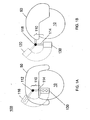
- FIGS. 1A-4 illustrate a helmet-mounted switch system 100 in accordance with aspects of the present invention.
- the helmet-mounted switch system 100 is adapted to be coupled to a helmet 50 that is worn on the head of a user 10.
- helmet-mounted switch system 100 includes a mount portion 110, an electronic device 130, a power source 150, a plurality of accelerometers 170, and a processor 190. Additional details of switch system 100 are described below.
- Mount portion 110 is coupled to helmet 50, as illustrated in FIGS. 1A and 1B .
- Mount portion 110 is configured to receive an electronic device to be mounted to helmet 50.
- Mount portion 110 may be adapted to move the electronic device between an active position and a stowed position.
- mount portion 110 is a rotatable helmet mount.
- Mount portion 110 is rotatable around a rotation axis 112. As illustrated in FIG. 1A , mount portion 110 may be rotatable around rotation axis 112 between an active position 114 and a stowed position 116.
- mount portion 110 is rotatable around another rotation axis 118. As illustrated in FIG. 1B , mount portion 110 may be rotatable around rotation axis 118 between the active position 114 and a stowed position 120. Stowed position 120 may be the same as or different from stowed position 116. Mount portion 110 may be rotatable around one or both of rotation axes 112 and 118. Thereby, mount portion 110 may be rotatable in two different rotational directions around axes 112 and 118, respectively, as illustrated in FIGS. 1A and 1B .
- Suitable rotatable helmet mounts for use as mount portion 110 include, for example, the Norotos INVG Mount, P/N 1820010.
- Other suitable helmet mounts for use as mount portion 110 will be known by one of ordinary skill in the art from the description herein.
- Electronic device 130 is configured to be mounted to mount portion 110, as illustrated in FIGS. 1A and 1B .
- Electronic device 130 may be a device that is configured for positioning in front of the eye of user 10.
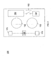
- electronic device 130 is a night vision device, as illustrated in FIG. 2 .
- the night vision device 130 may include one or more optical inputs 132 for receiving an image of a forward field of view. Suitable night vision devices for use as electronic device 130 will be known by one of ordinary skill in the art from the description herein.
- Power source 150 is configured to switchably supply power to electronic device 130.
- Power source 150 may be integrated with or incorporated into electronic device 130, as illustrated in FIG. 2 . Nonetheless, while power source 150 is illustrated as an internal component of electronic device 130, it will be understood that power source 150 may be a component external to electronic device 130.
- power source 150 may be coupled to helmet 50, and electrically connected with electronic device 130 in order to power electronic device 130.
- power source 150 is a battery configured to power electronic device 130.
- the battery is incorporated into the electronic device 130.
- Power source 150 may further include at least one switch 152, as illustrated in FIG. 2 .
- Switch 152 is connected between power source 150 and the electronic components of electronics device 130 (generally referred to as 134 in FIG. 2 ), and controls whether the components 134 of electronic device 130 receive power from power source 150.
- switch 152 may be actuated in order to turn electronic device 130 on and off.
- switch 152 may be a mechanical relay.
- Switch 152 may be electrically actuated, as will be described herein. While only a single switch 152 is illustrated, it will be understood that multiple switches 152 may be used to control power to multiple different circuits in electronic device 130.
- Accelerometers 170 are coupled to one of the mount portion 110 and the electronic device 130. Accelerometers 170 may be affixed to one or both of mount portion 110 and electronic device 130. In an exemplary embodiment, accelerometers 170 are integrated with or incorporated into electronic device 130, as illustrated in FIG. 2 . Nonetheless, while accelerometers 170 are illustrated as internal components of electronic device 130, it will be understood that accelerometers 170 may alternatively or additionally be coupled to mount portion 110. Accelerometers 170 may be powered by power source 150. Alternatively, accelerometers 170 may be powered by a separate power source. Accelerometers 170 may desirably be coupled such that they continue to receive power even when electronic device 130 has been powered down or placed in standby mode. Thus, accelerometers 170 will be able to sense movement of electronic device from the stowed position 116 to the active position 114, as will be explained herein.
- Accelerometers 170 are operable to measure the acceleration of one or both of the mount portion 110 and the electronic device 130. Accelerometers 170 may be operable to measure acceleration along one or multiple different axes.
- accelerometers 170 are dual axis MicroElectroMechanical Systems (MEMS) accelerometers. Accelerometers 170 have two measurement axes, i.e., they measure acceleration in two directions. Accelerometers 170 output a signal representing the acceleration measured in each direction.
- MEMS accelerometers for use as accelerometers 170 include, for example, the Analog Devices ADXL 335 3 Axis Accelerometer, or the Freescale MMA 7361L 3 Axis Accelerometer.
- Other suitable accelerometers for use as accelerometers 170 will be known by one of ordinary skill in the art from the description herein.
- accelerometers 170 may be important for detecting the movement of electronic device 130 when it is mounted to mount portion 110, as will be described herein.
- accelerometers 170 may be selected based on the location of the rotation axis of mount portion 110, as will be described below with reference to FIG. 3 .
- a first accelerometer 170A is positioned at a first distance r1 from rotation axis 112.
- a second accelerometer 170B is positioned at a second distance r2 from rotation axis 112. This may enable switch system 100 to identify when mount portion 110 is rotating around rotation axis 112.
- mount portion 110 may be rotatable around multiple rotation axes 112 and 118, as illustrated in FIG. 4 .
- a first accelerometer 170C is positioned at a first distance r1 from rotation axis 112 and a first distance r3 from rotation axis 118.
- a second accelerometer 170D is positioned at a second distance r2 from rotation axis 112 and a second distance r4 from rotation axis 118. This may enable switch system 100 to identify when mount portion 110 is rotating around rotation axis 112 and when mount portion is rotating around rotation axis 118. It will be understood that when mount portion 110 is rotatable around a third rotation axis, accelerometers 170C and 170D may be positioned at different distances from the third rotation axis, substantially as described above.
- accelerometers 170 may be selected based on the direction of rotation of mount portion 110, as will be described below with reference to FIGS. 3 and 4 .
- accelerometer 170A has a measurement axis a1.
- the measurement axis a1 is oriented in a direction substantially tangential to the direction of rotation of mount portion 110 around rotation axis 112. This may allow accelerometer 170A to more easily measure when mount portion 110 is rotating about its rotation axis 112.
- mount portion 110 is rotatable around multiple rotation axes 112 and 118
- accelerometer 170C has multiple measurement axes a1 and a2, as illustrated in FIG. 4 .
- the measurement axis a1 is oriented in a direction substantially tangential to the first direction of rotation of mount portion 110 around rotation axis 112
- measurement axis a2 is oriented in a direction substantially tangential to the second direction of rotation of mount portion 110 around rotation axis 118. This may also allow accelerometer 170C to more easily measure when mount portion 110 is rotating about its rotation axis 112 or when mount portion 110 is rotating about its rotation axis 118.
- At least one of the accelerometers 170 may be replaced with a gyroscope (not shown).
- a combination of accelerometer(s) and gyroscope(s) may be integrated with or incorporated into electronic device 130.
- Such a combination of accelerometers and gyroscopes may be referred to as an inertial measurement unit (IMU).
- IMU inertial measurement unit
- the one or more accelerometers 170 may be configured to measure the acceleration of either the mount portion 110 or the electronic device 130
- the one or more gyroscopes may be configured to measure the rotation of either the mount portion 110 or the electronic device 130. Thereby, it may be determined whether mount portion 110 is rotating around rotation axis 112.
- a processor 190 is configured to receive acceleration data measured by the plurality of accelerometers 170.
- Processor 190 may be integrated with or incorporated into electronic device 130, as illustrated in FIG. 2 .
- Processor 190 may be powered by power source 150.
- processor 190 is a microprocessor.
- processor 190 may be any circuit configured to receive data from accelerometers 170 and process the data. Suitable microprocessors for use as processor 190 will be known by one of ordinary skill in the art from the description herein.
- Processor 190 is programmed to determine whether mount portion 110 is rotating around a rotation axis based on the acceleration data received from accelerometers 170. An exemplary algorithm for determining whether mount portion 110 is rotating is described below with reference to FIG. 3 .
- accelerometers 170A and 170B measure an acceleration, and communicate their respective measured acceleration data to processor 190.
- processor 190 determines that the measured accelerations received from accelerometers 170A and 170B have a ratio approximately equivalent to r1 / r2, then processor 190 may determine that the measured acceleration corresponds to the rotation of mount portion 110 around rotation axis 112.
- processor 190 determines that the measured accelerations received from accelerometers 170A and 170B have a ratio substantially different from r1 / r2
- processor 190 may determine that the measured acceleration corresponds to a different movement of mount portion 110, e.g., a movement of helmet 50, to which mount portion 110 is attached.
- processor 190 may be operable to determine whether a measured movement of electronic device 130 or mount portion 110 corresponds to a rotation of mount portion 110 around rotation axis 112 or to a movement of helmet 50.
- accelerometers 170C and 170D when user 10 moves his or her head or body, the accelerations experienced by accelerometers 170C and 170D will not correspond to the above ratios, as the user's movements will generally not be around rotation axis 112 or rotation axis 118. This may allow for the differentiation of the movements of mount portion 110.
- processor 190 may be programmed to allow a tolerance in determining whether a measured acceleration corresponds to the above ratios.
- processor 190 may be programmed to determine the range of movement of mount portion 110 based on the measured acceleration data from accelerometers 170. It will be understood that movements of user 10 or helmet 50 worn by user 10 may be limited in angular range. Thus, if a movement measured by accelerometers 170 exceeds a predetermined range or angular distance, processor 190 may determine that the movement corresponds to a rotation of mount portion 110, as opposed to a movement of helmet 50. Thereby, processor 190 may be programmed to determine whether a measured acceleration corresponds to a rotation of mount portion 110 or corresponds to a movement of helmet 50 based on the range of movement of electronic device 130 measured by accelerometers 190. This process may be combined with the above-described algorithms to determine with greater accuracy whether mount portion 110 is rotating around a rotation axis.
- Processor 190 is programmed to change a power state of electronic device 130 when processor 190 determines that mount portion 110 is rotating around a rotation axis.
- processor 190 is electrically connected with switch 152.
- processor 190 determines that mount portion 110 is rotating around rotation axis 112
- processor 190 is programmed to transmit a signal to actuate switch 152, thereby connecting or disconnecting electronic device 130 from power supply 150.
- processor 190 determines that mount portion 110 is rotating around either rotation axis 112 or rotation axis 118, processor 190 is programmed to transmit a signal to actuate switch 152, thereby connecting or disconnecting electronic device 130 from power supply 150.
- processor 190 may be programmed to determine whether the mount portion 110 is rotating into the active position 114 or the stowed position 116. In an exemplary embodiment, processor 190 determines whether the mount portion 110 is rotating into the active position 114 or the stowed position 116 based on the direction (or polarity) of the acceleration measured by accelerometers 170 when it is determined that mount portion 110 is rotating around a rotation axis. When processor 190 determines that mount portion 110 is being rotated into the active position 114, processor 190 is programmed to transmit a signal to activate switch 152, thereby connecting electronic device 130 with power supply 150. This may enable electronic device 130 to be automatically turned on when electronic device 130 is rotated into the active position 114 by user 10.
- processor 190 determines that mount portion 110 is being rotated into the stowed position 116
- processor 190 is programmed to transmit a signal to deactivate switch 152, thereby disconnecting electronic device 130 from power supply 150.
- This may enable electronic device 130 to be automatically turned off when electronic device 130 is rotated into the stowed position 116 by user 10.
- electronic device 130 may be changed to a low power state, e.g. a standby mode, when electronic device 130 is rotated into the stowed position 116. This may enable systems on standby mode to be quickly powered on when electronic device is rotated from the stowed position 116 to the active position 114.
- FIG. 5 illustrates a method 200 for operating a helmet-mounted switch system in accordance with aspects of the present invention.
- the helmet-mounted switch system includes a mount portion rotatable around a rotation axis and an electronic device mounted to the mount portion.
- method 200 includes measuring an acceleration, determining whether the mount portion is rotating, and connecting or disconnecting the electronic device from a power supply. Additional details of method 200 are described below.
- an acceleration is measured.
- the acceleration of either mount portion 110 or electronic device 130 are measured with accelerometers 170.
- a first accelerometer 170A may measure the acceleration at a first distance r1 from rotation axis 112
- a second accelerometer 170B may measure the acceleration at a second distance r2 from rotation axis 112, as described above with respect to FIG. 3 .
- a first accelerometer 170C may measure the acceleration at a first distance r1 from rotation axis 112 and a first distance r3 from rotation axis 118
- a second accelerometer 170D may measure the acceleration at a second distance r2 from rotation axis 112 and a second distance r4 from rotation axis 118, as described above with respect to FIG. 4
- an accelerometer 170 may include a measurement axis a1 oriented in a direction tangential to the direction of rotation of mount portion 110, as described above with respect to FIGS. 3 and 4 .
- step 230 it is determined whether the mount portion is rotating.
- processor 190 determines whether the mount portion 110 is rotating around a rotation axis based on the accelerations measured by accelerometers 170.
- Processor 190 may determine whether the mount portion 110 is rotating using the above-described algorithms.
- Processor 190 may further be programmed to determine whether the mount portion 110 is rotating around a rotation axis 112, whether mount portion 110 is rotating around rotation axis 118, or whether helmet 50 is moving, as described above.
- a power state of the electronic device is changed.
- processor 190 connects or disconnects electronic device 130 with power supply 150 when processor 190 determines that mount portion 110 is rotation around the rotation axis.
- electronic device 130 may be switched between a normal mode and a standby mode when processor 190 determines that mount portion 110 is rotation around the rotation axis.
- convention systems may use mechanical switches to automatically turn on and off an association electronic device. These switches may utilize mechanical contacts to open or close the switch as the helmet mount moves between an active and stowed position.
- Mechanical switches may suffer from reliability issues and in the complexity of mounting and alignment. The incorporation of mechanical switches into the helmet mount may increase the helmet's complexity and cost, and reduce reliability. Additionally, mechanical switches such as level sensors or tilt sensors may be unable to distinguish between the movement of the mount portion between positions and a movement of the user's head.
- the disclosed systems and methods may incorporate one or more accelerometers mounted inside an electronic device, thereby eliminating the need for electrical interconnection through the wall of the electronic device.
- the exemplary MEMS accelerometers are inexpensive and rugged. They may be easily incorporated into other electronic components inside an electronic device, making final incorporation inexpensive.
- This invention allows both direct reading of accelerations in addition to allowing for signal integration to determine velocity and distance to allow discrimination between movements of the mount portion or electronic device alone, as opposed to a user's head movements.
Landscapes
- Helmets And Other Head Coverings (AREA)
Claims (13)
- Ein an einem Helm montiertes Schaltsystem (100), umfassend:ein um eine Drehachse (112, 118) drehbares Befestigungsteil (110);ein am Befestigungsteil (110) befestigtes elektronisches Gerät (130);eine Stromquelle (150), das zur Versorgung des elektronischen Geräts (130) schaltbar ist;gekennzeichnet durch:eine Vielzahl von Beschleunigungssensoren (170; 170A-170D) betreibbar, um eine Beschleunigung des Befestigungsteils (110) zu messen; undeinen Prozessor (190) konfiguriert, um Beschleunigungsdaten aus der Vielzahl von Beschleunigungssensoren (170; 170A-170D) zu erhalten;wobei der Prozessor (190) programmiert ist, um zu bestimmen, ob das Befestigungsteil (110) sich um die Drehachse (112, 118) dreht, basierend auf den Beschleunigungsdaten, undder Prozessor (190) programmiert ist, um einen Betriebszustand der elektronischen Vorrichtung (130) zu ändern, wenn das Befestigungsteil (110) sich um die Drehachse (112, 118) dreht.
- Schaltsystem nach Anspruch 1, wobei:- die Vielzahl von Beschleunigungssensoren (170; 170A-170D) in die elektronischen Vorrichtung (130) integriert sind; oder- die Vielzahl von Beschleunigungssensoren (170; 170A-170D) betreibbar sind, um eine Beschleunigung in einer Richtung im Wesentlichen tangential zu einer Drehrichtung des Befestigungsteil (110) zu messen.
- Schaltsystem nach Anspruch 1, wobei:mindestens einer von der Mehrzahl von Beschleunigungssensoren (170A, 170C) in einem ersten Abstand (r1) von der Drehachse (112) positioniert ist, undmindestens ein anderer von der Mehrzahl von Beschleunigungssensoren (170B, 170D) in einem zweiten Abstand (r2) von der Drehachse (112) positioniert ist, verschieden vom ersten Abstand (r1).
- Schaltsystem nach Anspruch 1, wobei:der Prozessor (190) programmiert ist, um- zu bestimmen, ob eine gemessene Beschleunigung einer Drehung des Befestigungsteils (110) um die Drehachse (112, 118) oder eine Bewegung eines mit dem Befestigungsteil (110) verbundenen Helmes (50) entspricht; oder- zu bestimmen, ob das Befestigungsteil (110) sich in eine aktive Stellung (114) oder in eine eingefahrene Stellung (116) dreht,der Prozessor (190) programmiert ist, um die elektronische Vorrichtung (130) mit der Stromversorgung (150) zu verbinden, wenn der Prozessor (190) bestimmt, dass das Befestigungsteil (110) sich in die aktive Stellung (114) dreht, undder Prozessor (190) programmiert ist, um die elektronische Vorrichtung (130) von der Stromversorgung (150) zu trennen, wenn der Prozessor (190) bestimmt, dass das Befestigungsteil (110) sich in der verstauten Stellung (116) dreht.
- Schaltsystem nach Anspruch 1, wobei:das Befestigungsteil (110) um eine erste Drehachse (112) und eine zweite Drehachse (118) drehbar ist, undder Prozessor (190) programmiert ist, um den Betriebszustand der elektronischen Vorrichtung (130) zu ändern, wenn der Prozessor (190) bestimmt, dass das Befestigungsteil (110) um die erste Drehachse (112) oder die zweite Drehachse (118) sich dreht.
- Schaltsystem nach Anspruch 5, wobei:- mindestens einer von der Mehrzahl von Beschleunigungssensoren (170A, 170C) in einem ersten Abstand (r1) von der ersten Drehachse (112) und einem ersten Abstand (r3) von der zweiten Drehachse (118) positioniert ist, und
mindestens ein anderer von der Mehrzahl von Beschleunigungssensoren (170B, 170D) in einem zweiten Abstand (r2) von der ersten Drehachse (112), verschieden vom ersten Abstand (r1), und einem zweiten Abstand (r4) von der zweiten Drehachse (118), verscheiden vom ersten Abstand (r3) positioniert ist; oder- der Prozessor (190) so programmiert ist, dass er bestimmt, ob eine gemessene Beschleunigung einer Drehung des Befestigungsteils (110) um die erste Drehachse (112), eine Drehung des Befestigungsteils (110) um die zweite Drehachse (118) oder eine Bewegung eines mit dem Befestigungsteil (110) verbundenen Helmes (50) entspricht. - Schaltsystem nach Anspruch 1, ferner umfasst:wenigstens einen Kreisel betreibbar, um eine Drehung des Befestigungsteils (110) zu messen, wobei der Prozessor (190) programmiert ist, um zu bestimmen, ob das Befestigungsteil (110) um die Drehachse (112, 118) sich dreht, basierend auf den Beschleunigungsdaten und Rotationsdaten gemessen vom wenigstens einen Kreisel.
- Schaltsystem nach Anspruch 1, ferner umfasst:wenigstens einen Kreisel betreibbar, um eine Drehung des Befestigungsteils (110) zu messen, wobei der Prozessor (190) so ausgestaltet ist, dass er Rotationsdaten vom wenigstens einen Kreisel erhält.
- Verfahren zum Betreiben eines an einem Helm montierten Schaltsystems (100), wobei das an einem Helm montierte Schaltsystem (100) ein Befestigungsteil (110), das um eine Drehachse (112, 118) drehbar ist, und eine am Befestigungsteil (110) befestigte elektronische Vorrichtung (130) umfasst, wobei das Verfahren die Schritte aufweist:Messen einer Beschleunigung des Befestigungsteils (110);Bestimmen, ob das Befestigungsteil (110) um die Drehachse (112, 118) auf Basis der gemessenen Beschleunigung sich dreht; undÄndern eines Betriebsstatus der elektronischen Vorrichtung (130), wenn das Befestigungsteil (110) sich um die Drehachse (112, 118) dreht;wobei der Messschritt aufweist:- Messen der Beschleunigung des Befestigungsteils (110) oder der elektronischen Vorrichtung (130), mit einem ersten Beschleunigungssensor (170A, 170C) in einem ersten Abstand (r1) von der Drehachse (112) positioniert, und- Messen der Beschleunigung des Befestigungsteils (110) oder der elektronischen Vorrichtung (130), mit einem zweiten Beschleunigungssensor (170B, 170D) in einem zweiten Abstand (r2) von der Drehachse (112) positioniert, verschieden vom ersten Abstand (r1).
- Verfahren nach Anspruch 9, wobei der Bestimmungsschritt umfasst:Bestimmen, ob die gemessene Beschleunigung einer Drehung des Befestigungsteils (110) um die Drehachse (112, 118) oder eine Bewegung eines mit dem Befestigungsteil (110) verbundenen Helmes (50) entspricht.
- Verfahren nach Anspruch 9, wobei das Befestigungsteil (110) um eine erste Drehachse (112) und eine zweite Drehachse (118) drehbar ist, und wobei der Änderungsschritt umfasst:Verbinden oder trennen der elektronischen Vorrichtung (130) mit einer Stromversorgung (150), wenn bestimmt wird, dass das Befestigungsteil (110) sich um die erste Drehachse (112) oder die zweite Drehachse (118) dreht.
- Verfahren nach Anspruch 11, wobei der Messschritt umfasst:Messen der Beschleunigung des Befestigungsteil (110) oder der elektronischen Vorrichtung (130) mit einem ersten Beschleunigungssensor (170A, 170C), der in einem ersten Abstand (r1) von der ersten Drehachse (112) und in einem ersten Abstand (r3) von der zweiten Drehachse (118) positioniert ist, undMessen der Beschleunigung des Befestigungsteils (110) oder der elektronischen Vorrichtung (130) mit einem zweiten Beschleunigungssensor (170B. 170D), der in einem zweiten Abstand (r2) von der ersten Drehachse (112), verschieden vom ersten Abstand (r1), und einem zweiten Abstand (r4) von der zweiten Drehachse (118), verscheiden vom ersten Abstand (r3) positioniert ist.
- Verfahren nach Anspruch 11, wobei der Bestimmungsschritt umfasst:Bestimmen, ob die gemessene Beschleunigung einer Drehung des Befestigungsteils (110) um die erste Drehachse (112), eine Drehung des Befestigungsteils (110) um die zweite Drehachse (118) oder einer Bewegung eines mit dem Montageteil (110) verbundenen Helmes (50) entspricht.
Applications Claiming Priority (2)
| Application Number | Priority Date | Filing Date | Title |
|---|---|---|---|
| US12/789,703 US8497465B2 (en) | 2010-05-28 | 2010-05-28 | Orientation sensing switch system for a head-mounted electronic device |
| PCT/US2011/036912 WO2011149728A1 (en) | 2010-05-28 | 2011-05-18 | Switch system for helmet mounted electronic device |
Publications (2)
| Publication Number | Publication Date |
|---|---|
| EP2575520A1 EP2575520A1 (de) | 2013-04-10 |
| EP2575520B1 true EP2575520B1 (de) | 2014-11-19 |
Family
ID=44356182
Family Applications (1)
| Application Number | Title | Priority Date | Filing Date |
|---|---|---|---|
| EP11726983.7A Active EP2575520B1 (de) | 2010-05-28 | 2011-05-18 | Schaltsystem für eine helmmontierte elektronische vorrichtung |
Country Status (7)
| Country | Link |
|---|---|
| US (1) | US8497465B2 (de) |
| EP (1) | EP2575520B1 (de) |
| JP (1) | JP5860040B2 (de) |
| AU (1) | AU2011258690B2 (de) |
| CA (1) | CA2800875A1 (de) |
| IL (1) | IL223061A (de) |
| WO (1) | WO2011149728A1 (de) |
Families Citing this family (13)
| Publication number | Priority date | Publication date | Assignee | Title |
|---|---|---|---|---|
| US8721103B2 (en) * | 2009-11-03 | 2014-05-13 | Levi Jacob Robinson | Utility helmet with integrated lighting system |
| US10051908B2 (en) * | 2012-06-28 | 2018-08-21 | Revision Military S.A.R.L. | Helmet-mounted display |
| IL226701A (en) * | 2013-06-03 | 2017-07-31 | Itl Optronics Ltd | Platform Composite Device Control System and Method |
| US9575721B2 (en) | 2013-07-25 | 2017-02-21 | Lg Electronics Inc. | Head mounted display and method of controlling therefor |
| KR102086511B1 (ko) * | 2013-07-25 | 2020-03-09 | 엘지전자 주식회사 | 헤드 마운티드 디스플레이 및 그 제어 방법 |
| KR101546193B1 (ko) | 2014-07-18 | 2015-08-20 | 배진형 | 스마트 헬멧 |
| US20160109914A1 (en) * | 2014-10-16 | 2016-04-21 | Google Inc. | Wearable device without a power button |
| JP2017069736A (ja) * | 2015-09-30 | 2017-04-06 | ブラザー工業株式会社 | ヘッドマウントディスプレイ |
| CN105286166A (zh) * | 2015-11-25 | 2016-02-03 | 张明 | 一种后视前放安全智能头盔 |
| US9943127B2 (en) | 2015-11-30 | 2018-04-17 | Revision Military S.A.R.L. | Adjustable connector for a helmet accessory |
| EP3846652B1 (de) | 2018-09-04 | 2026-03-18 | Designworks Defence Systems Pty Ltd | Schaltvorrichtung mit betriebsmoduserfassung und multiorientiertes montagesystem für eine helmmontierte nachtsichtvorrichtung |
| US11204649B2 (en) * | 2020-01-30 | 2021-12-21 | SA Photonics, Inc. | Head-mounted display with user-operated control |
| US11675422B2 (en) * | 2021-05-27 | 2023-06-13 | Meta Platforms Technologies, Llc | System for user presence detection |
Family Cites Families (13)
| Publication number | Priority date | Publication date | Assignee | Title |
|---|---|---|---|---|
| JPH05228855A (ja) * | 1992-02-19 | 1993-09-07 | Yaskawa Electric Corp | テレイグジスタンス視覚装置 |
| US5408086A (en) | 1993-06-24 | 1995-04-18 | Litton Systems, Inc. | Head-mounted flip-up night vision device with automatic turn-off upon flip-up |
| US5506730A (en) | 1993-09-09 | 1996-04-09 | Litton Systems, Inc. | Flip-up helmet mount for night vision goggle |
| JPH08311712A (ja) * | 1995-05-15 | 1996-11-26 | Tadashi Sakama | ヘルメット |
| US6087660A (en) * | 1997-11-14 | 2000-07-11 | Litton Systems, Inc. | Night vision device and method |
| US20030207718A1 (en) | 2000-10-20 | 2003-11-06 | Perlmutter Michael S. | Methods and systems for analyzing the motion of sporting equipment |
| US6862748B2 (en) | 2003-03-17 | 2005-03-08 | Norotos Inc | Magnet module for night vision goggles helmet mount |
| US7128434B1 (en) | 2003-07-28 | 2006-10-31 | Sportcraft, Ltd. | Lighted headgear with motion activated switch |
| US7219370B1 (en) | 2003-10-06 | 2007-05-22 | Wilcox Industries Corp. | Helmet mounting systems |
| US7221263B2 (en) | 2003-10-23 | 2007-05-22 | Zero Nine Design, Llc | Helmet lighting system |
| US7504918B2 (en) | 2005-06-23 | 2009-03-17 | Norotos, Inc. | Magnetically activated switch |
| TWI307835B (en) * | 2005-09-14 | 2009-03-21 | Quanta Comp Inc | Portable electronic device and method of auto switching power mode |
| US8519984B2 (en) * | 2009-08-20 | 2013-08-27 | Acer Incorporated | Input device and display system having the same |
-
2010
- 2010-05-28 US US12/789,703 patent/US8497465B2/en active Active
-
2011
- 2011-05-18 CA CA2800875A patent/CA2800875A1/en not_active Abandoned
- 2011-05-18 AU AU2011258690A patent/AU2011258690B2/en not_active Expired - Fee Related
- 2011-05-18 WO PCT/US2011/036912 patent/WO2011149728A1/en not_active Ceased
- 2011-05-18 EP EP11726983.7A patent/EP2575520B1/de active Active
- 2011-05-18 JP JP2013512077A patent/JP5860040B2/ja not_active Expired - Fee Related
-
2012
- 2012-11-15 IL IL223061A patent/IL223061A/en active IP Right Grant
Also Published As
| Publication number | Publication date |
|---|---|
| CA2800875A1 (en) | 2011-12-01 |
| WO2011149728A1 (en) | 2011-12-01 |
| JP2013531744A (ja) | 2013-08-08 |
| US20110289661A1 (en) | 2011-12-01 |
| JP5860040B2 (ja) | 2016-02-16 |
| US8497465B2 (en) | 2013-07-30 |
| IL223061A (en) | 2015-10-29 |
| IL223061A0 (en) | 2013-02-03 |
| AU2011258690B2 (en) | 2014-11-13 |
| AU2011258690A1 (en) | 2012-12-06 |
| EP2575520A1 (de) | 2013-04-10 |
Similar Documents
| Publication | Publication Date | Title |
|---|---|---|
| EP2575520B1 (de) | Schaltsystem für eine helmmontierte elektronische vorrichtung | |
| US12554286B2 (en) | Headset computer that uses motion and voice commands to control information display and remote devices | |
| US10851981B1 (en) | Cordless LED headlight and control thereof | |
| US20210127774A1 (en) | Operational mode sensing switch system and multi-oriented mounting system for a helmet mounted night vision device | |
| ES2720299T3 (es) | Aparato de control, cabezal de soporte que usa el mismo, y método de control de cabezal de soporte | |
| TWI473576B (zh) | 自動警示行車方向之裝置 | |
| EP3417338B1 (de) | Modulares zusätzliches head-up-display für erweiterte realität, schnittstellen und steuerungen | |
| JP6690179B2 (ja) | 挙動推定システム、及び挙動推定方法 | |
| WO2013176997A1 (en) | Augmented reality motorcycle helmet | |
| JP2004108939A (ja) | 測量機の遠隔操作システム | |
| JP7147527B2 (ja) | 支援装置、支援方法およびプログラム | |
| US9925921B1 (en) | Head tracking control system for controlling an auxiliary vehicle light | |
| US9751607B1 (en) | Method and system for controlling rotatable device on marine vessel | |
| KR101989576B1 (ko) | 차량용 안전 삼각대 장치 | |
| EP2412576A2 (de) | Notausstiegbeleuchtungssystem | |
| AU2022291459B2 (en) | Operational mode sensing switch system and multi-orientated mounting system for a helmet mounted night vision device | |
| JP2024013342A (ja) | 制御装置、頭部装着型表示装置の制御方法及びプログラム | |
| JP2008285773A (ja) | ヘルメット | |
| Guenthner et al. | Biomimetic control for adaptive camera stabilization in driver-assistance systems | |
| CA2747518A1 (en) | Emergency egress lighting system |
Legal Events
| Date | Code | Title | Description |
|---|---|---|---|
| PUAI | Public reference made under article 153(3) epc to a published international application that has entered the european phase |
Free format text: ORIGINAL CODE: 0009012 |
|
| 17P | Request for examination filed |
Effective date: 20121128 |
|
| AK | Designated contracting states |
Kind code of ref document: A1 Designated state(s): AL AT BE BG CH CY CZ DE DK EE ES FI FR GB GR HR HU IE IS IT LI LT LU LV MC MK MT NL NO PL PT RO RS SE SI SK SM TR |
|
| DAX | Request for extension of the european patent (deleted) | ||
| 17Q | First examination report despatched |
Effective date: 20131031 |
|
| GRAP | Despatch of communication of intention to grant a patent |
Free format text: ORIGINAL CODE: EPIDOSNIGR1 |
|
| INTG | Intention to grant announced |
Effective date: 20140319 |
|
| GRAP | Despatch of communication of intention to grant a patent |
Free format text: ORIGINAL CODE: EPIDOSNIGR1 |
|
| INTG | Intention to grant announced |
Effective date: 20140814 |
|
| GRAS | Grant fee paid |
Free format text: ORIGINAL CODE: EPIDOSNIGR3 |
|
| GRAA | (expected) grant |
Free format text: ORIGINAL CODE: 0009210 |
|
| AK | Designated contracting states |
Kind code of ref document: B1 Designated state(s): AL AT BE BG CH CY CZ DE DK EE ES FI FR GB GR HR HU IE IS IT LI LT LU LV MC MK MT NL NO PL PT RO RS SE SI SK SM TR |
|
| REG | Reference to a national code |
Ref country code: GB Ref legal event code: FG4D |
|
| REG | Reference to a national code |
Ref country code: CH Ref legal event code: EP |
|
| REG | Reference to a national code |
Ref country code: AT Ref legal event code: REF Ref document number: 696475 Country of ref document: AT Kind code of ref document: T Effective date: 20141215 |
|
| REG | Reference to a national code |
Ref country code: IE Ref legal event code: FG4D |
|
| REG | Reference to a national code |
Ref country code: DE Ref legal event code: R096 Ref document number: 602011011534 Country of ref document: DE Effective date: 20141231 |
|
| REG | Reference to a national code |
Ref country code: NL Ref legal event code: VDEP Effective date: 20141119 |
|
| REG | Reference to a national code |
Ref country code: AT Ref legal event code: MK05 Ref document number: 696475 Country of ref document: AT Kind code of ref document: T Effective date: 20141119 |
|
| REG | Reference to a national code |
Ref country code: LT Ref legal event code: MG4D |
|
| PG25 | Lapsed in a contracting state [announced via postgrant information from national office to epo] |
Ref country code: FI Free format text: LAPSE BECAUSE OF FAILURE TO SUBMIT A TRANSLATION OF THE DESCRIPTION OR TO PAY THE FEE WITHIN THE PRESCRIBED TIME-LIMIT Effective date: 20141119 Ref country code: NL Free format text: LAPSE BECAUSE OF FAILURE TO SUBMIT A TRANSLATION OF THE DESCRIPTION OR TO PAY THE FEE WITHIN THE PRESCRIBED TIME-LIMIT Effective date: 20141119 Ref country code: ES Free format text: LAPSE BECAUSE OF FAILURE TO SUBMIT A TRANSLATION OF THE DESCRIPTION OR TO PAY THE FEE WITHIN THE PRESCRIBED TIME-LIMIT Effective date: 20141119 Ref country code: LT Free format text: LAPSE BECAUSE OF FAILURE TO SUBMIT A TRANSLATION OF THE DESCRIPTION OR TO PAY THE FEE WITHIN THE PRESCRIBED TIME-LIMIT Effective date: 20141119 Ref country code: NO Free format text: LAPSE BECAUSE OF FAILURE TO SUBMIT A TRANSLATION OF THE DESCRIPTION OR TO PAY THE FEE WITHIN THE PRESCRIBED TIME-LIMIT Effective date: 20150219 Ref country code: PT Free format text: LAPSE BECAUSE OF FAILURE TO SUBMIT A TRANSLATION OF THE DESCRIPTION OR TO PAY THE FEE WITHIN THE PRESCRIBED TIME-LIMIT Effective date: 20150319 Ref country code: IS Free format text: LAPSE BECAUSE OF FAILURE TO SUBMIT A TRANSLATION OF THE DESCRIPTION OR TO PAY THE FEE WITHIN THE PRESCRIBED TIME-LIMIT Effective date: 20150319 |
|
| PG25 | Lapsed in a contracting state [announced via postgrant information from national office to epo] |
Ref country code: AT Free format text: LAPSE BECAUSE OF FAILURE TO SUBMIT A TRANSLATION OF THE DESCRIPTION OR TO PAY THE FEE WITHIN THE PRESCRIBED TIME-LIMIT Effective date: 20141119 Ref country code: LV Free format text: LAPSE BECAUSE OF FAILURE TO SUBMIT A TRANSLATION OF THE DESCRIPTION OR TO PAY THE FEE WITHIN THE PRESCRIBED TIME-LIMIT Effective date: 20141119 Ref country code: GR Free format text: LAPSE BECAUSE OF FAILURE TO SUBMIT A TRANSLATION OF THE DESCRIPTION OR TO PAY THE FEE WITHIN THE PRESCRIBED TIME-LIMIT Effective date: 20150220 Ref country code: SE Free format text: LAPSE BECAUSE OF FAILURE TO SUBMIT A TRANSLATION OF THE DESCRIPTION OR TO PAY THE FEE WITHIN THE PRESCRIBED TIME-LIMIT Effective date: 20141119 Ref country code: RS Free format text: LAPSE BECAUSE OF FAILURE TO SUBMIT A TRANSLATION OF THE DESCRIPTION OR TO PAY THE FEE WITHIN THE PRESCRIBED TIME-LIMIT Effective date: 20141119 Ref country code: PL Free format text: LAPSE BECAUSE OF FAILURE TO SUBMIT A TRANSLATION OF THE DESCRIPTION OR TO PAY THE FEE WITHIN THE PRESCRIBED TIME-LIMIT Effective date: 20141119 Ref country code: HR Free format text: LAPSE BECAUSE OF FAILURE TO SUBMIT A TRANSLATION OF THE DESCRIPTION OR TO PAY THE FEE WITHIN THE PRESCRIBED TIME-LIMIT Effective date: 20141119 Ref country code: CY Free format text: LAPSE BECAUSE OF FAILURE TO SUBMIT A TRANSLATION OF THE DESCRIPTION OR TO PAY THE FEE WITHIN THE PRESCRIBED TIME-LIMIT Effective date: 20141119 |
|
| PG25 | Lapsed in a contracting state [announced via postgrant information from national office to epo] |
Ref country code: SK Free format text: LAPSE BECAUSE OF FAILURE TO SUBMIT A TRANSLATION OF THE DESCRIPTION OR TO PAY THE FEE WITHIN THE PRESCRIBED TIME-LIMIT Effective date: 20141119 Ref country code: RO Free format text: LAPSE BECAUSE OF FAILURE TO SUBMIT A TRANSLATION OF THE DESCRIPTION OR TO PAY THE FEE WITHIN THE PRESCRIBED TIME-LIMIT Effective date: 20141119 Ref country code: EE Free format text: LAPSE BECAUSE OF FAILURE TO SUBMIT A TRANSLATION OF THE DESCRIPTION OR TO PAY THE FEE WITHIN THE PRESCRIBED TIME-LIMIT Effective date: 20141119 Ref country code: CZ Free format text: LAPSE BECAUSE OF FAILURE TO SUBMIT A TRANSLATION OF THE DESCRIPTION OR TO PAY THE FEE WITHIN THE PRESCRIBED TIME-LIMIT Effective date: 20141119 Ref country code: DK Free format text: LAPSE BECAUSE OF FAILURE TO SUBMIT A TRANSLATION OF THE DESCRIPTION OR TO PAY THE FEE WITHIN THE PRESCRIBED TIME-LIMIT Effective date: 20141119 |
|
| REG | Reference to a national code |
Ref country code: DE Ref legal event code: R097 Ref document number: 602011011534 Country of ref document: DE |
|
| PLBE | No opposition filed within time limit |
Free format text: ORIGINAL CODE: 0009261 |
|
| STAA | Information on the status of an ep patent application or granted ep patent |
Free format text: STATUS: NO OPPOSITION FILED WITHIN TIME LIMIT |
|
| REG | Reference to a national code |
Ref country code: FR Ref legal event code: PLFP Year of fee payment: 5 |
|
| 26N | No opposition filed |
Effective date: 20150820 |
|
| PG25 | Lapsed in a contracting state [announced via postgrant information from national office to epo] |
Ref country code: IT Free format text: LAPSE BECAUSE OF FAILURE TO SUBMIT A TRANSLATION OF THE DESCRIPTION OR TO PAY THE FEE WITHIN THE PRESCRIBED TIME-LIMIT Effective date: 20141119 |
|
| REG | Reference to a national code |
Ref country code: CH Ref legal event code: PL |
|
| PG25 | Lapsed in a contracting state [announced via postgrant information from national office to epo] |
Ref country code: CH Free format text: LAPSE BECAUSE OF NON-PAYMENT OF DUE FEES Effective date: 20150531 Ref country code: LU Free format text: LAPSE BECAUSE OF FAILURE TO SUBMIT A TRANSLATION OF THE DESCRIPTION OR TO PAY THE FEE WITHIN THE PRESCRIBED TIME-LIMIT Effective date: 20150518 Ref country code: LI Free format text: LAPSE BECAUSE OF NON-PAYMENT OF DUE FEES Effective date: 20150531 Ref country code: MC Free format text: LAPSE BECAUSE OF FAILURE TO SUBMIT A TRANSLATION OF THE DESCRIPTION OR TO PAY THE FEE WITHIN THE PRESCRIBED TIME-LIMIT Effective date: 20141119 |
|
| REG | Reference to a national code |
Ref country code: IE Ref legal event code: MM4A |
|
| PG25 | Lapsed in a contracting state [announced via postgrant information from national office to epo] |
Ref country code: SI Free format text: LAPSE BECAUSE OF FAILURE TO SUBMIT A TRANSLATION OF THE DESCRIPTION OR TO PAY THE FEE WITHIN THE PRESCRIBED TIME-LIMIT Effective date: 20141119 |
|
| PG25 | Lapsed in a contracting state [announced via postgrant information from national office to epo] |
Ref country code: IE Free format text: LAPSE BECAUSE OF NON-PAYMENT OF DUE FEES Effective date: 20150518 |
|
| REG | Reference to a national code |
Ref country code: FR Ref legal event code: PLFP Year of fee payment: 6 |
|
| PG25 | Lapsed in a contracting state [announced via postgrant information from national office to epo] |
Ref country code: MT Free format text: LAPSE BECAUSE OF FAILURE TO SUBMIT A TRANSLATION OF THE DESCRIPTION OR TO PAY THE FEE WITHIN THE PRESCRIBED TIME-LIMIT Effective date: 20141119 |
|
| REG | Reference to a national code |
Ref country code: FR Ref legal event code: PLFP Year of fee payment: 7 |
|
| PG25 | Lapsed in a contracting state [announced via postgrant information from national office to epo] |
Ref country code: SM Free format text: LAPSE BECAUSE OF FAILURE TO SUBMIT A TRANSLATION OF THE DESCRIPTION OR TO PAY THE FEE WITHIN THE PRESCRIBED TIME-LIMIT Effective date: 20141119 Ref country code: HU Free format text: LAPSE BECAUSE OF FAILURE TO SUBMIT A TRANSLATION OF THE DESCRIPTION OR TO PAY THE FEE WITHIN THE PRESCRIBED TIME-LIMIT; INVALID AB INITIO Effective date: 20110518 Ref country code: BG Free format text: LAPSE BECAUSE OF FAILURE TO SUBMIT A TRANSLATION OF THE DESCRIPTION OR TO PAY THE FEE WITHIN THE PRESCRIBED TIME-LIMIT Effective date: 20141119 |
|
| PG25 | Lapsed in a contracting state [announced via postgrant information from national office to epo] |
Ref country code: TR Free format text: LAPSE BECAUSE OF FAILURE TO SUBMIT A TRANSLATION OF THE DESCRIPTION OR TO PAY THE FEE WITHIN THE PRESCRIBED TIME-LIMIT Effective date: 20141119 |
|
| PG25 | Lapsed in a contracting state [announced via postgrant information from national office to epo] |
Ref country code: BE Free format text: LAPSE BECAUSE OF FAILURE TO SUBMIT A TRANSLATION OF THE DESCRIPTION OR TO PAY THE FEE WITHIN THE PRESCRIBED TIME-LIMIT Effective date: 20141119 |
|
| REG | Reference to a national code |
Ref country code: FR Ref legal event code: PLFP Year of fee payment: 8 |
|
| PG25 | Lapsed in a contracting state [announced via postgrant information from national office to epo] |
Ref country code: MK Free format text: LAPSE BECAUSE OF FAILURE TO SUBMIT A TRANSLATION OF THE DESCRIPTION OR TO PAY THE FEE WITHIN THE PRESCRIBED TIME-LIMIT Effective date: 20141119 |
|
| PG25 | Lapsed in a contracting state [announced via postgrant information from national office to epo] |
Ref country code: AL Free format text: LAPSE BECAUSE OF FAILURE TO SUBMIT A TRANSLATION OF THE DESCRIPTION OR TO PAY THE FEE WITHIN THE PRESCRIBED TIME-LIMIT Effective date: 20141119 |
|
| REG | Reference to a national code |
Ref country code: DE Ref legal event code: R082 Ref document number: 602011011534 Country of ref document: DE Representative=s name: K&L GATES LLP, DE Ref country code: DE Ref legal event code: R081 Ref document number: 602011011534 Country of ref document: DE Owner name: ELBIT SYSTEMS OF AMERICA, LLC (N.D. GES. D. ST, US Free format text: FORMER OWNER: EXELIS INC., MCLEAN, VA., US |
|
| P01 | Opt-out of the competence of the unified patent court (upc) registered |
Effective date: 20230627 |
|
| PGFP | Annual fee paid to national office [announced via postgrant information from national office to epo] |
Ref country code: DE Payment date: 20250519 Year of fee payment: 15 |
|
| PGFP | Annual fee paid to national office [announced via postgrant information from national office to epo] |
Ref country code: GB Payment date: 20250527 Year of fee payment: 15 |
|
| PGFP | Annual fee paid to national office [announced via postgrant information from national office to epo] |
Ref country code: FR Payment date: 20250526 Year of fee payment: 15 |