EP2575586B1 - Aspirateur à alimentation en air de balayage - Google Patents
Aspirateur à alimentation en air de balayage Download PDFInfo
- Publication number
- EP2575586B1 EP2575586B1 EP11720800.9A EP11720800A EP2575586B1 EP 2575586 B1 EP2575586 B1 EP 2575586B1 EP 11720800 A EP11720800 A EP 11720800A EP 2575586 B1 EP2575586 B1 EP 2575586B1
- Authority
- EP
- European Patent Office
- Prior art keywords
- vacuum cleaner
- closing body
- accordance
- closure member
- filter
- Prior art date
- Legal status (The legal status is an assumption and is not a legal conclusion. Google has not performed a legal analysis and makes no representation as to the accuracy of the status listed.)
- Not-in-force
Links
Images

Classifications
-
- A—HUMAN NECESSITIES
- A47—FURNITURE; DOMESTIC ARTICLES OR APPLIANCES; COFFEE MILLS; SPICE MILLS; SUCTION CLEANERS IN GENERAL
- A47L—DOMESTIC WASHING OR CLEANING; SUCTION CLEANERS IN GENERAL
- A47L9/00—Details or accessories of suction cleaners, e.g. mechanical means for controlling the suction or for effecting pulsating action; Storing devices specially adapted to suction cleaners or parts thereof; Carrying-vehicles specially adapted for suction cleaners
- A47L9/20—Means for cleaning filters
-
- A—HUMAN NECESSITIES
- A47—FURNITURE; DOMESTIC ARTICLES OR APPLIANCES; COFFEE MILLS; SPICE MILLS; SUCTION CLEANERS IN GENERAL
- A47L—DOMESTIC WASHING OR CLEANING; SUCTION CLEANERS IN GENERAL
- A47L5/00—Structural features of suction cleaners
- A47L5/12—Structural features of suction cleaners with power-driven air-pumps or air-compressors, e.g. driven by motor vehicle engine vacuum
- A47L5/22—Structural features of suction cleaners with power-driven air-pumps or air-compressors, e.g. driven by motor vehicle engine vacuum with rotary fans
- A47L5/36—Suction cleaners with hose between nozzle and casing; Suction cleaners for fixing on staircases; Suction cleaners for carrying on the back
- A47L5/365—Suction cleaners with hose between nozzle and casing; Suction cleaners for fixing on staircases; Suction cleaners for carrying on the back of the vertical type, e.g. tank or bucket type
-
- A—HUMAN NECESSITIES
- A47—FURNITURE; DOMESTIC ARTICLES OR APPLIANCES; COFFEE MILLS; SPICE MILLS; SUCTION CLEANERS IN GENERAL
- A47L—DOMESTIC WASHING OR CLEANING; SUCTION CLEANERS IN GENERAL
- A47L9/00—Details or accessories of suction cleaners, e.g. mechanical means for controlling the suction or for effecting pulsating action; Storing devices specially adapted to suction cleaners or parts thereof; Carrying-vehicles specially adapted for suction cleaners
- A47L9/10—Filters; Dust separators; Dust removal; Automatic exchange of filters
- A47L9/12—Dry filters
- A47L9/122—Dry filters flat
Definitions
- the invention relates to a vacuum cleaner with a dirt collecting container which has a suction inlet and is in flow connection via at least one filter and a suction line with a suction unit, and with a scavenging air supply means for supplying scavenging air into the suction line downstream of the filter, wherein the scavenging air supply means comprises at least one scavenging air opening and a sleeve-shaped closing body, which in a closed position by means of at least two cooperating sealing elements, which are displaceable relative to each other in a direction of movement, prevents the inflow of scavenging air through the at least one scavenging air in the suction and manually in the direction of movement in the inflow of scavenging air on the at least one scavenging air opening in the suction line releasing release position is movable.
- the vacuum cleaner has at least one filter which is arranged in the flow path between the dirt collecting container and the suction unit. At the side of the at least one filter facing the dirt collecting container, dirt particles gradually accumulate during the suction operation of the vacuum cleaner. It is therefore necessary to clean the at least one filter after some time, otherwise the suction flow generated by the suction unit in the region of the filter experiences a strong pressure drop, so that an effective suction operation of the vacuum cleaner is no longer guaranteed.
- the dirt collecting container side facing away from the filter can be acted upon with purging air.
- the vacuum cleaner on the scavenging air supply means for supplying scavenging air into the suction downstream of the filter.
- the purge air supply device comprises at least one purge air opening, which is in flow communication with the suction line. The inflow of purging air via the scavenging air opening into the suction line can optionally be prevented or released.
- the scavenging air supply device comprises the sleeve-shaped closing body, which prevents the inflow of scavenging air in its closed position, and releases in its release position.
- the closing body During the normal suction operation of the vacuum cleaner, the inflow is prevented by the closing body assumes its closed position.
- the closing body is designed in the manner of a sleeve, and can be moved manually in a direction of movement, starting from a closed position, in its release position. In the release position, scavenging air can flow into the suction line and act on the side of the at least one filter remote from the dirt collecting container.
- the filter is mechanically shaken, and at least part of the inflowing scavenging air can flow through the at least one filter in the counterflow direction, ie counter to the direction of the suction flow prevailing during the normal suction operation, so that dirt particles adhering to the filter are not only caused by the scavenging air mechanical vibration of the filter are replaced but also directly through the filter in the counterflow direction flowing purge air.
- a vacuum cleaner of the type mentioned is from the published patent application WO 97/19630 A1 known.
- the scavenging air supply device has a housing which is of tubular design and has lateral scavenging air openings.
- a sleeve-shaped closing body is held coaxially displaceable relative to its longitudinal axis.
- the closing body has side openings in a similar manner as the tubular housing.
- a 1 known vacuum cleaner acts on the closing body in its closed position permanently a pressure difference resulting from the pressure prevailing inside and outside of the closing body.
- Within the closing body acts during the normal suction operation prevailing in the suction vacuum, and outside the closing body acts on it atmospheric pressure.
- the pressure difference results in a compressive force that acts on the closing body in the direction of its release position.
- the closing body is acted upon by a return spring with a restoring force opposite to the pressing force. If the closing body is moved by the user starting from its closed position in the direction of its release position, the movement is supported by the pressure force acting on the closing body until the closing body reaches its release position.
- the purge air supply means comprises a plate-shaped closing body which is held by means of an electromagnet against the action of a compressive force in its closed position. After switching off the exciting current of the electromagnet, the closing body can be moved by the pressing force in its release position. Also in this vacuum cleaner, the forces acting on the closing body abruptly change as soon as the closing body reaches its release position, since then eliminates the pressure difference prevailing on the closing body.
- the closing body used in the vacuum cleaner according to the invention is designed to be elongated in the manner of a sleeve. It has a circumferentially extending peripheral wall, and a first and a second end face. Both ends are open.
- the inflow of scavenging air is prevented in the closed position of the closing body by means of at least two sealing elements, which are displaceable relative to each other in the direction of movement of the closing body.
- the sealing elements can be arranged for example in the region of the peripheral wall. It can also be provided that two sealing elements are arranged in the region of one end face of the sleeve-shaped closing body.
- sealing elements form a sealing ring and a sealing surface associated with the sealing ring.
- the sealing ring or alternatively the sealing surface may be arranged on the closing body.
- a sealing element is arranged on an end face of the closing body.
- the inflow of scavenging air through the at least one scavenging air opening in the suction line is prevented in such a configuration in the closed position of the closing body by the end-side sealing element. If the closing body is moved in the axial direction, then the sealing element gives the inflow of purging air free, and purging air can flow past the sealing element with aligned transversely to the longitudinal axis of the closing body flow direction.
- the holding force decreases abruptly after the start of the movement of the closing body, in particular.
- the user must first exert a significant operating force on the closing body to trigger a cleaning process, so that in the closed position acting on the closing body holding force can be overcome. Only then the movement of the closing body is set in motion, but then the holding force abruptly drops or completely eliminated.
- This has the advantage that the user intuitively loads the closing body with a considerable actuating force, which greatly accelerates the closing body after overcoming the holding force, so that it assumes its release position within a short time.
- the closing body in the closed position can be acted upon by a holding force which is dependent on the pressure in the suction line and which has to be overcome by the user in order to trigger the movement of the closing body.
- the closing body is acted upon in the closed position with a larger holding force, the greater the negative pressure prevailing in the suction line downstream of the filter. If the flow connection between the at least one purge air opening and the suction line is released, then reduced the negative pressure in the suction line, and the holding force decreases abruptly.
- the closing body is coupled to a manually actuable plunger.
- the plunger may have a plunger shaft which engages through an actuating opening of a housing of the scavenging air supply device and carries at its protruding from the housing end a widening plunger head, which can be acted upon by the user with a compressive force.
- the plunger shaft can thus be pressed by the user in the housing of the scavenging air supply, and thereby the Closing body to be moved from its closed position to its release position.
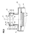
- FIG. 3 A third embodiment of a vacuum cleaner according to the invention is shown schematically in Figure 3 in a partial sectional view. Identical components are in FIG. 3 with the same reference numerals as in FIG. 1 , In terms of These components will be referred to the foregoing explanations to avoid repetition.
- the line section 138 of the suction line 18 forms in the in FIG. 3 illustrated embodiment, the housing of the scavenging air supply 134, which is surrounded by the sleeve-like closing body 142.
- a separate suction line is used, as in FIG. 3 is indicated by the arrow 160 shown in dashed lines.
- the housing 136 is closed on its side facing away from the filter 16 top 162, but it also has the side scavenging air openings 140, which are covered in the closed position of the sleeve-like closure member 142.
Landscapes
- Engineering & Computer Science (AREA)
- Mechanical Engineering (AREA)
- Nozzles For Electric Vacuum Cleaners (AREA)
Claims (18)
- Aspirateur équipé d'un récipient collecteur de saletés (10), qui présente une entrée d'aspiration (12) et est en communication fluidique avec une unité aspiratrice par l'intermédiaire d'au moins un filtre (16) et d'un conduit d'aspiration (18), et d'un dispositif d'alimentation en air de balayage (24 ; 84 ; 134) pour amener de l'air de balayage dans le conduit d'aspiration (18) en aval du filtre (16), le dispositif d'alimentation en air de balayage (24 ; 84 ; 134) présentant au moins une ouverture d'air de balayage (34 ; 114 ; 140) ainsi qu'un corps de fermeture (48 ; 86 ; 142) en forme de douille qui, en position de fermeture, à l'aide d'au moins deux éléments d'étanchéité qui coopèrent l'un avec l'autre et peuvent être déplacés l'un par rapport à l'autre dans un sens de mouvement empêche l'entrée d'air de balayage par cette ou ces ouvertures d'air de balayage (34 ; 114 ; 140) dans le conduit d'aspiration (18), et qui, dans le sens de mouvement, peut être déplacé manuellement dans une position de libération libérant l'entrée d'air de balayage par la ou les ouvertures d'air de balayage dans le conduit d'aspiration, caractérisé en ce que le corps de fermeture (48, 86, 142) est ouvert sur ses deux faces frontales (56, 64 ; 104, 106).
- Aspirateur selon la revendication 1, caractérisé en ce qu'au moins deux des éléments d'étanchéité s'étendent dans la direction circonférentielle du corps de fermeture (48 ; 86 ; 142).
- Aspirateur selon la revendication 2, caractérisé en ce que les deux éléments d'étanchéité ou plus s'étendent le long de toute la circonférence du corps de fermeture (48 ; 86 ; 142).
- Aspirateur selon l'une quelconque des revendications précédentes, caractérisé en ce que deux des éléments d'étanchéité forment un joint à labyrinthe (52).
- Aspirateur selon l'une quelconque des revendications précédentes, caractérisé en ce qu'au moins deux des éléments d'étanchéité forment un joint annulaire (60 ; 110 ; 154, 156) et une surface d'étanchéité (58 ; 108) associée au joint annulaire.
- Aspirateur selon l'une quelconque des revendications précédentes, caractérisé en ce qu'au moins un des éléments d'étanchéité est agencé sur une face frontale (56 ; 106) du corps de fermeture (48 ; 86).
- Aspirateur selon la revendication 6, caractérisé en ce que l'élément d'étanchéité forme une surface d'étanchéité circulaire (58 ; 108).
- Aspirateur selon l'une quelconque des revendications précédentes, caractérisé en ce que le corps de fermeture (48), en position de fermeture, peut être soumis à l'effet d'une force de retenue que l'utilisateur doit vaincre pour déclencher le mouvement du corps de fermeture (48).
- Aspirateur selon la revendication 8, caractérisé en ce que la force de retenue s'évanouit une fois le mouvement du corps de fermeture (48) mis en action.
- Aspirateur selon la revendication 8 ou 9, caractérisé en ce que le corps de fermeture (48), en position de fermeture, peut être soumis à l'effet d'une force de retenue dépendant de la pression dans le conduit d'aspiration (18).
- Aspirateur selon la revendication 6, caractérisé en ce que le corps de fermeture (48) s'élargit radialement en direction de la face frontale (56) sur laquelle est agencé au moins un des éléments d'étanchéité.
- Aspirateur selon l'une quelconque des revendications précédentes, caractérisé en ce que le corps de fermeture (48) est couplé à une tige de poussée (40) pouvant être actionnée manuellement.
- Aspirateur selon l'une quelconque des revendications 1 à 11, caractérisé en ce que le corps de fermeture (86) est couplé à une tige de traction (96) pouvant être actionnée manuellement.
- Aspirateur selon l'une quelconque des revendications précédentes, caractérisé en ce que le corps de fermeture (48 ; 86 ; 142) repose coulissant sur une partie de guidage.
- Aspirateur selon la revendication 14, caractérisé en ce qu'un boîtier (90 ; 136) du dispositif d'alimentation en air de balayage (84 ; 134) forme la partie de guidage.
- Aspirateur selon la revendication 14, caractérisé en ce qu'une section (138) du conduit d'aspiration (18) forme la partie de guidage.
- Aspirateur selon la revendication 15, caractérisé en ce que la partie de guidage présente la ou les ouvertures d'air de balayage (140).
- Aspirateur selon l'une quelconque des revendications précédentes, caractérisé en ce que la communication fluidique entre le ou les filtres (16) et l'unité aspiratrice peut être interrompue en mettant le corps de fermeture (48 ; 86) dans sa position de libération.
Applications Claiming Priority (2)
| Application Number | Priority Date | Filing Date | Title |
|---|---|---|---|
| DE102010029518A DE102010029518A1 (de) | 2010-05-31 | 2010-05-31 | Staubsauger |
| PCT/EP2011/058417 WO2011151217A1 (fr) | 2010-05-31 | 2011-05-24 | Aspirateur à alimentation en air de balayage |
Publications (2)
| Publication Number | Publication Date |
|---|---|
| EP2575586A1 EP2575586A1 (fr) | 2013-04-10 |
| EP2575586B1 true EP2575586B1 (fr) | 2014-03-19 |
Family
ID=44119215
Family Applications (1)
| Application Number | Title | Priority Date | Filing Date |
|---|---|---|---|
| EP11720800.9A Not-in-force EP2575586B1 (fr) | 2010-05-31 | 2011-05-24 | Aspirateur à alimentation en air de balayage |
Country Status (3)
| Country | Link |
|---|---|
| EP (1) | EP2575586B1 (fr) |
| DE (1) | DE102010029518A1 (fr) |
| WO (1) | WO2011151217A1 (fr) |
Cited By (1)
| Publication number | Priority date | Publication date | Assignee | Title |
|---|---|---|---|---|
| US10729299B2 (en) | 2016-01-19 | 2020-08-04 | Festool Gmbh | Suction device |
Families Citing this family (9)
| Publication number | Priority date | Publication date | Assignee | Title |
|---|---|---|---|---|
| DE102013108559A1 (de) | 2013-08-08 | 2015-02-12 | Miele & Cie. Kg | Verfahren zum Betrieb eines Staubsaugers zum Rückreinigen eines vom Staubsauger umfassten Filterelements |
| CN108903806B (zh) * | 2018-08-17 | 2023-08-22 | 莱克电气股份有限公司 | 一种用于海帕自清洁式吸尘器的风道快速切换结构 |
| CN108903805B (zh) * | 2018-08-17 | 2023-07-04 | 莱克电气股份有限公司 | 一种用于海帕自清洁式吸尘器的电机底座 |
| CN108937723B (zh) * | 2018-08-17 | 2023-07-04 | 莱克电气股份有限公司 | 一种用于海帕自清洁式吸尘器的风道快速切换装置 |
| CN108888171B (zh) * | 2018-08-17 | 2023-07-25 | 莱克电气股份有限公司 | 一种反向吹风式自清洁吸尘器 |
| DE102019117920A1 (de) | 2019-07-03 | 2021-01-07 | Alfred Kärcher SE & Co. KG | Saugvorrichtung und Verfahren zur Abreinigung eines Filters |
| DE102023103425A1 (de) | 2023-02-13 | 2024-08-14 | Festool Gmbh | Sauggerät mit einem Abreinigungsventil |
| DE102023133671A1 (de) | 2023-12-01 | 2025-06-05 | Alfred Kärcher SE & Co. KG | Sauger mit Filter-Abreinigungseinrichtung-Modul |
| CN119302554B (zh) * | 2024-12-17 | 2025-06-03 | 江苏日新电器科技有限公司 | 一种净化空气的吸尘器 |
Family Cites Families (5)
| Publication number | Priority date | Publication date | Assignee | Title |
|---|---|---|---|---|
| US3431709A (en) * | 1967-09-25 | 1969-03-11 | Sanko Seisakusho Kk | Dust collector |
| EP0873075B1 (fr) | 1995-11-30 | 2000-02-02 | Alfred Kärcher GmbH & Co. | Dispositif d'aspiration a des fins de nettoyage |
| DE29823411U1 (de) | 1998-05-08 | 1999-05-20 | Alfred Kärcher GmbH & Co, 71364 Winnenden | Sauggerät für Reinigungszwecke |
| DE102005017568B4 (de) * | 2005-04-11 | 2024-04-25 | Alfred Kärcher SE & Co. KG | Saugreinigungsgerät |
| DK2046182T3 (da) | 2006-07-29 | 2014-08-18 | Kaercher Gmbh & Co Kg Alfred | Støvsuger med selvrensende filterindretning |
-
2010
- 2010-05-31 DE DE102010029518A patent/DE102010029518A1/de not_active Withdrawn
-
2011
- 2011-05-24 WO PCT/EP2011/058417 patent/WO2011151217A1/fr not_active Ceased
- 2011-05-24 EP EP11720800.9A patent/EP2575586B1/fr not_active Not-in-force
Cited By (1)
| Publication number | Priority date | Publication date | Assignee | Title |
|---|---|---|---|---|
| US10729299B2 (en) | 2016-01-19 | 2020-08-04 | Festool Gmbh | Suction device |
Also Published As
| Publication number | Publication date |
|---|---|
| WO2011151217A1 (fr) | 2011-12-08 |
| EP2575586A1 (fr) | 2013-04-10 |
| DE102010029518A1 (de) | 2011-12-01 |
Similar Documents
| Publication | Publication Date | Title |
|---|---|---|
| EP2575586B1 (fr) | Aspirateur à alimentation en air de balayage | |
| EP2575587B1 (fr) | Aspirateur avec nettoyage de filtre par contre-courant | |
| DE69816669T2 (de) | Rückspülbare flüssigkeitsfilter mit schleuderabreinigung | |
| EP3514427B1 (fr) | Dispositif d'actionnement de soupape | |
| EP0665321B1 (fr) | Dispositif d'injection d'eau pour fer à repasser à vapeur | |
| EP3249271B1 (fr) | Dispositif d'actionnement de soupape et procédé de commutation d'un système de soupape | |
| EP3513008B1 (fr) | Unité d'écoulement sanitaire | |
| DE102016010335A1 (de) | Ablaufgarnitur für einen WC-Spülkasten | |
| DE102019117920A1 (de) | Saugvorrichtung und Verfahren zur Abreinigung eines Filters | |
| WO2018206508A1 (fr) | Disque d'extrémité, élément filtre, système filtre et procédé de filtrage d'un liquide | |
| DE10326766B4 (de) | Antriebsvorrichtung zum Vorschub eines Vorschubelements und Verfahren zur Ausschüttung eines fluiden Produkts aus einem Behälter | |
| DE3323324C3 (de) | Verfahren und Vorrichtung zum Steuern eines Rohrtrenners in Abhängigkeit einer an einer Vergleichsstelle vorgegebenen Druckdifferenz | |
| WO1997006878A1 (fr) | Petit filtre compact portable, a usage manuel, pour le traitement de l'eau | |
| DE202020105008U1 (de) | Sanitäre Ventilanordnung und Verwendung einer sanitären Ventilanordnung | |
| EP3699465A1 (fr) | Dispositif de soupape d'inversion | |
| DE2262508B2 (de) | Loesbare verbindungsanordnung fuer einen rohrstutzen und einen schlauch | |
| DE102017131230A1 (de) | Sanitärarmatur | |
| EP0195389B2 (fr) | Déconnecteur de tuyaux | |
| WO2018041399A1 (fr) | Dispositif d'actionnement d'une soupape de vidange d'un réservoir de chasse d'eau | |
| DE102013006602B4 (de) | Sanitärbrause mit einem Brausekopf | |
| DE102017005959A1 (de) | Vorrichtung zur Betätigung eines Ablaufventils eines WC-Spülkastens | |
| DE202026101050U1 (de) | Filtereinrichtung mit einer drückbetätigten, schnell demontier- und montierbaren Filterkartuschen-Baugruppe | |
| DE102007032839B4 (de) | Wasserauslauf für eine sanitäre Niederdruck-Auslaufarmatur | |
| DE1600981C (fr) | ||
| EP1491830B1 (fr) | Chauffe-eau électrique |
Legal Events
| Date | Code | Title | Description |
|---|---|---|---|
| PUAI | Public reference made under article 153(3) epc to a published international application that has entered the european phase |
Free format text: ORIGINAL CODE: 0009012 |
|
| 17P | Request for examination filed |
Effective date: 20121129 |
|
| AK | Designated contracting states |
Kind code of ref document: A1 Designated state(s): AL AT BE BG CH CY CZ DE DK EE ES FI FR GB GR HR HU IE IS IT LI LT LU LV MC MK MT NL NO PL PT RO RS SE SI SK SM TR |
|
| DAX | Request for extension of the european patent (deleted) | ||
| GRAP | Despatch of communication of intention to grant a patent |
Free format text: ORIGINAL CODE: EPIDOSNIGR1 |
|
| INTG | Intention to grant announced |
Effective date: 20131004 |
|
| GRAS | Grant fee paid |
Free format text: ORIGINAL CODE: EPIDOSNIGR3 |
|
| GRAA | (expected) grant |
Free format text: ORIGINAL CODE: 0009210 |
|
| AK | Designated contracting states |
Kind code of ref document: B1 Designated state(s): AL AT BE BG CH CY CZ DE DK EE ES FI FR GB GR HR HU IE IS IT LI LT LU LV MC MK MT NL NO PL PT RO RS SE SI SK SM TR |
|
| REG | Reference to a national code |
Ref country code: GB Ref legal event code: FG4D Free format text: NOT ENGLISH |
|
| REG | Reference to a national code |
Ref country code: CH Ref legal event code: EP Ref country code: CH Ref legal event code: NV Representative=s name: ISLER AND PEDRAZZINI AG, CH |
|
| REG | Reference to a national code |
Ref country code: AT Ref legal event code: REF Ref document number: 657095 Country of ref document: AT Kind code of ref document: T Effective date: 20140415 |
|
| REG | Reference to a national code |
Ref country code: IE Ref legal event code: FG4D Free format text: LANGUAGE OF EP DOCUMENT: GERMAN |
|
| REG | Reference to a national code |
Ref country code: DE Ref legal event code: R096 Ref document number: 502011002478 Country of ref document: DE Effective date: 20140430 |
|
| PG25 | Lapsed in a contracting state [announced via postgrant information from national office to epo] |
Ref country code: LT Free format text: LAPSE BECAUSE OF FAILURE TO SUBMIT A TRANSLATION OF THE DESCRIPTION OR TO PAY THE FEE WITHIN THE PRESCRIBED TIME-LIMIT Effective date: 20140319 Ref country code: NO Free format text: LAPSE BECAUSE OF FAILURE TO SUBMIT A TRANSLATION OF THE DESCRIPTION OR TO PAY THE FEE WITHIN THE PRESCRIBED TIME-LIMIT Effective date: 20140619 |
|
| REG | Reference to a national code |
Ref country code: NL Ref legal event code: VDEP Effective date: 20140319 |
|
| REG | Reference to a national code |
Ref country code: LT Ref legal event code: MG4D |
|
| PG25 | Lapsed in a contracting state [announced via postgrant information from national office to epo] |
Ref country code: CY Free format text: LAPSE BECAUSE OF FAILURE TO SUBMIT A TRANSLATION OF THE DESCRIPTION OR TO PAY THE FEE WITHIN THE PRESCRIBED TIME-LIMIT Effective date: 20140319 Ref country code: FI Free format text: LAPSE BECAUSE OF FAILURE TO SUBMIT A TRANSLATION OF THE DESCRIPTION OR TO PAY THE FEE WITHIN THE PRESCRIBED TIME-LIMIT Effective date: 20140319 Ref country code: SE Free format text: LAPSE BECAUSE OF FAILURE TO SUBMIT A TRANSLATION OF THE DESCRIPTION OR TO PAY THE FEE WITHIN THE PRESCRIBED TIME-LIMIT Effective date: 20140319 |
|
| PG25 | Lapsed in a contracting state [announced via postgrant information from national office to epo] |
Ref country code: LV Free format text: LAPSE BECAUSE OF FAILURE TO SUBMIT A TRANSLATION OF THE DESCRIPTION OR TO PAY THE FEE WITHIN THE PRESCRIBED TIME-LIMIT Effective date: 20140319 Ref country code: RS Free format text: LAPSE BECAUSE OF FAILURE TO SUBMIT A TRANSLATION OF THE DESCRIPTION OR TO PAY THE FEE WITHIN THE PRESCRIBED TIME-LIMIT Effective date: 20140319 Ref country code: HR Free format text: LAPSE BECAUSE OF FAILURE TO SUBMIT A TRANSLATION OF THE DESCRIPTION OR TO PAY THE FEE WITHIN THE PRESCRIBED TIME-LIMIT Effective date: 20140319 |
|
| PG25 | Lapsed in a contracting state [announced via postgrant information from national office to epo] |
Ref country code: IS Free format text: LAPSE BECAUSE OF FAILURE TO SUBMIT A TRANSLATION OF THE DESCRIPTION OR TO PAY THE FEE WITHIN THE PRESCRIBED TIME-LIMIT Effective date: 20140719 Ref country code: RO Free format text: LAPSE BECAUSE OF FAILURE TO SUBMIT A TRANSLATION OF THE DESCRIPTION OR TO PAY THE FEE WITHIN THE PRESCRIBED TIME-LIMIT Effective date: 20140319 Ref country code: EE Free format text: LAPSE BECAUSE OF FAILURE TO SUBMIT A TRANSLATION OF THE DESCRIPTION OR TO PAY THE FEE WITHIN THE PRESCRIBED TIME-LIMIT Effective date: 20140319 Ref country code: BG Free format text: LAPSE BECAUSE OF FAILURE TO SUBMIT A TRANSLATION OF THE DESCRIPTION OR TO PAY THE FEE WITHIN THE PRESCRIBED TIME-LIMIT Effective date: 20140619 Ref country code: NL Free format text: LAPSE BECAUSE OF FAILURE TO SUBMIT A TRANSLATION OF THE DESCRIPTION OR TO PAY THE FEE WITHIN THE PRESCRIBED TIME-LIMIT Effective date: 20140319 Ref country code: CZ Free format text: LAPSE BECAUSE OF FAILURE TO SUBMIT A TRANSLATION OF THE DESCRIPTION OR TO PAY THE FEE WITHIN THE PRESCRIBED TIME-LIMIT Effective date: 20140319 |
|
| PG25 | Lapsed in a contracting state [announced via postgrant information from national office to epo] |
Ref country code: ES Free format text: LAPSE BECAUSE OF FAILURE TO SUBMIT A TRANSLATION OF THE DESCRIPTION OR TO PAY THE FEE WITHIN THE PRESCRIBED TIME-LIMIT Effective date: 20140319 Ref country code: SK Free format text: LAPSE BECAUSE OF FAILURE TO SUBMIT A TRANSLATION OF THE DESCRIPTION OR TO PAY THE FEE WITHIN THE PRESCRIBED TIME-LIMIT Effective date: 20140319 Ref country code: PL Free format text: LAPSE BECAUSE OF FAILURE TO SUBMIT A TRANSLATION OF THE DESCRIPTION OR TO PAY THE FEE WITHIN THE PRESCRIBED TIME-LIMIT Effective date: 20140319 |
|
| REG | Reference to a national code |
Ref country code: DE Ref legal event code: R097 Ref document number: 502011002478 Country of ref document: DE |
|
| PG25 | Lapsed in a contracting state [announced via postgrant information from national office to epo] |
Ref country code: LU Free format text: LAPSE BECAUSE OF FAILURE TO SUBMIT A TRANSLATION OF THE DESCRIPTION OR TO PAY THE FEE WITHIN THE PRESCRIBED TIME-LIMIT Effective date: 20140524 Ref country code: PT Free format text: LAPSE BECAUSE OF FAILURE TO SUBMIT A TRANSLATION OF THE DESCRIPTION OR TO PAY THE FEE WITHIN THE PRESCRIBED TIME-LIMIT Effective date: 20140721 |
|
| PLBE | No opposition filed within time limit |
Free format text: ORIGINAL CODE: 0009261 |
|
| STAA | Information on the status of an ep patent application or granted ep patent |
Free format text: STATUS: NO OPPOSITION FILED WITHIN TIME LIMIT |
|
| PG25 | Lapsed in a contracting state [announced via postgrant information from national office to epo] |
Ref country code: DK Free format text: LAPSE BECAUSE OF FAILURE TO SUBMIT A TRANSLATION OF THE DESCRIPTION OR TO PAY THE FEE WITHIN THE PRESCRIBED TIME-LIMIT Effective date: 20140319 Ref country code: MC Free format text: LAPSE BECAUSE OF FAILURE TO SUBMIT A TRANSLATION OF THE DESCRIPTION OR TO PAY THE FEE WITHIN THE PRESCRIBED TIME-LIMIT Effective date: 20140319 |
|
| 26N | No opposition filed |
Effective date: 20141222 |
|
| REG | Reference to a national code |
Ref country code: IE Ref legal event code: MM4A |
|
| REG | Reference to a national code |
Ref country code: DE Ref legal event code: R097 Ref document number: 502011002478 Country of ref document: DE Effective date: 20141222 |
|
| PG25 | Lapsed in a contracting state [announced via postgrant information from national office to epo] |
Ref country code: IE Free format text: LAPSE BECAUSE OF NON-PAYMENT OF DUE FEES Effective date: 20140524 |
|
| REG | Reference to a national code |
Ref country code: DE Ref legal event code: R082 Ref document number: 502011002478 Country of ref document: DE Representative=s name: HOEGER, STELLRECHT & PARTNER PATENTANWAELTE MB, DE |
|
| PG25 | Lapsed in a contracting state [announced via postgrant information from national office to epo] |
Ref country code: SI Free format text: LAPSE BECAUSE OF FAILURE TO SUBMIT A TRANSLATION OF THE DESCRIPTION OR TO PAY THE FEE WITHIN THE PRESCRIBED TIME-LIMIT Effective date: 20140319 |
|
| PG25 | Lapsed in a contracting state [announced via postgrant information from national office to epo] |
Ref country code: MT Free format text: LAPSE BECAUSE OF FAILURE TO SUBMIT A TRANSLATION OF THE DESCRIPTION OR TO PAY THE FEE WITHIN THE PRESCRIBED TIME-LIMIT Effective date: 20140319 |
|
| REG | Reference to a national code |
Ref country code: FR Ref legal event code: PLFP Year of fee payment: 6 |
|
| PG25 | Lapsed in a contracting state [announced via postgrant information from national office to epo] |
Ref country code: SM Free format text: LAPSE BECAUSE OF FAILURE TO SUBMIT A TRANSLATION OF THE DESCRIPTION OR TO PAY THE FEE WITHIN THE PRESCRIBED TIME-LIMIT Effective date: 20140319 |
|
| PG25 | Lapsed in a contracting state [announced via postgrant information from national office to epo] |
Ref country code: GR Free format text: LAPSE BECAUSE OF FAILURE TO SUBMIT A TRANSLATION OF THE DESCRIPTION OR TO PAY THE FEE WITHIN THE PRESCRIBED TIME-LIMIT Effective date: 20140620 |
|
| PG25 | Lapsed in a contracting state [announced via postgrant information from national office to epo] |
Ref country code: BE Free format text: LAPSE BECAUSE OF FAILURE TO SUBMIT A TRANSLATION OF THE DESCRIPTION OR TO PAY THE FEE WITHIN THE PRESCRIBED TIME-LIMIT Effective date: 20140531 Ref country code: HU Free format text: LAPSE BECAUSE OF FAILURE TO SUBMIT A TRANSLATION OF THE DESCRIPTION OR TO PAY THE FEE WITHIN THE PRESCRIBED TIME-LIMIT; INVALID AB INITIO Effective date: 20110524 Ref country code: TR Free format text: LAPSE BECAUSE OF FAILURE TO SUBMIT A TRANSLATION OF THE DESCRIPTION OR TO PAY THE FEE WITHIN THE PRESCRIBED TIME-LIMIT Effective date: 20140319 |
|
| REG | Reference to a national code |
Ref country code: FR Ref legal event code: PLFP Year of fee payment: 7 |
|
| REG | Reference to a national code |
Ref country code: FR Ref legal event code: PLFP Year of fee payment: 8 |
|
| PG25 | Lapsed in a contracting state [announced via postgrant information from national office to epo] |
Ref country code: MK Free format text: LAPSE BECAUSE OF FAILURE TO SUBMIT A TRANSLATION OF THE DESCRIPTION OR TO PAY THE FEE WITHIN THE PRESCRIBED TIME-LIMIT Effective date: 20140319 |
|
| REG | Reference to a national code |
Ref country code: DE Ref legal event code: R082 Ref document number: 502011002478 Country of ref document: DE Representative=s name: HOEGER, STELLRECHT & PARTNER PATENTANWAELTE MB, DE Ref country code: DE Ref legal event code: R081 Ref document number: 502011002478 Country of ref document: DE Owner name: ALFRED KAERCHER SE & CO. KG, DE Free format text: FORMER OWNER: ALFRED KAERCHER GMBH & CO. KG, 71364 WINNENDEN, DE |
|
| PGFP | Annual fee paid to national office [announced via postgrant information from national office to epo] |
Ref country code: CH Payment date: 20180516 Year of fee payment: 8 |
|
| PGFP | Annual fee paid to national office [announced via postgrant information from national office to epo] |
Ref country code: IT Payment date: 20180529 Year of fee payment: 8 Ref country code: IT Payment date: 20180522 Year of fee payment: 8 |
|
| PG25 | Lapsed in a contracting state [announced via postgrant information from national office to epo] |
Ref country code: AL Free format text: LAPSE BECAUSE OF FAILURE TO SUBMIT A TRANSLATION OF THE DESCRIPTION OR TO PAY THE FEE WITHIN THE PRESCRIBED TIME-LIMIT Effective date: 20140319 |
|
| REG | Reference to a national code |
Ref country code: DE Ref legal event code: R082 Ref document number: 502011002478 Country of ref document: DE Representative=s name: HOEGER, STELLRECHT & PARTNER PATENTANWAELTE MB, DE |
|
| PGFP | Annual fee paid to national office [announced via postgrant information from national office to epo] |
Ref country code: FR Payment date: 20190603 Year of fee payment: 9 |
|
| PGFP | Annual fee paid to national office [announced via postgrant information from national office to epo] |
Ref country code: GB Payment date: 20190522 Year of fee payment: 9 |
|
| REG | Reference to a national code |
Ref country code: CH Ref legal event code: PL |
|
| REG | Reference to a national code |
Ref country code: AT Ref legal event code: MM01 Ref document number: 657095 Country of ref document: AT Kind code of ref document: T Effective date: 20190524 |
|
| PG25 | Lapsed in a contracting state [announced via postgrant information from national office to epo] |
Ref country code: CH Free format text: LAPSE BECAUSE OF NON-PAYMENT OF DUE FEES Effective date: 20190531 Ref country code: LI Free format text: LAPSE BECAUSE OF NON-PAYMENT OF DUE FEES Effective date: 20190531 Ref country code: AT Free format text: LAPSE BECAUSE OF NON-PAYMENT OF DUE FEES Effective date: 20190524 |
|
| PG25 | Lapsed in a contracting state [announced via postgrant information from national office to epo] |
Ref country code: IT Free format text: LAPSE BECAUSE OF NON-PAYMENT OF DUE FEES Effective date: 20190524 |
|
| GBPC | Gb: european patent ceased through non-payment of renewal fee |
Effective date: 20200524 |
|
| PG25 | Lapsed in a contracting state [announced via postgrant information from national office to epo] |
Ref country code: FR Free format text: LAPSE BECAUSE OF NON-PAYMENT OF DUE FEES Effective date: 20200531 Ref country code: GB Free format text: LAPSE BECAUSE OF NON-PAYMENT OF DUE FEES Effective date: 20200524 |
|
| P01 | Opt-out of the competence of the unified patent court (upc) registered |
Effective date: 20230521 |
|
| PGFP | Annual fee paid to national office [announced via postgrant information from national office to epo] |
Ref country code: DE Payment date: 20240524 Year of fee payment: 14 |
|
| REG | Reference to a national code |
Ref country code: DE Ref legal event code: R119 Ref document number: 502011002478 Country of ref document: DE |
|
| PG25 | Lapsed in a contracting state [announced via postgrant information from national office to epo] |
Ref country code: DE Free format text: LAPSE BECAUSE OF NON-PAYMENT OF DUE FEES Effective date: 20251202 |