EP2576038B1 - Couvercle de fermeture pour recipient equipe d'un joint d'etancheite - Google Patents
Couvercle de fermeture pour recipient equipe d'un joint d'etancheite Download PDFInfo
- Publication number
- EP2576038B1 EP2576038B1 EP11725168.6A EP11725168A EP2576038B1 EP 2576038 B1 EP2576038 B1 EP 2576038B1 EP 11725168 A EP11725168 A EP 11725168A EP 2576038 B1 EP2576038 B1 EP 2576038B1
- Authority
- EP
- European Patent Office
- Prior art keywords
- cover
- seal
- stirring means
- container
- passage
- Prior art date
- Legal status (The legal status is an assumption and is not a legal conclusion. Google has not performed a legal analysis and makes no representation as to the accuracy of the status listed.)
- Active
Links
Images

Classifications
-
- B—PERFORMING OPERATIONS; TRANSPORTING
- B01—PHYSICAL OR CHEMICAL PROCESSES OR APPARATUS IN GENERAL
- B01F—MIXING, e.g. DISSOLVING, EMULSIFYING OR DISPERSING
- B01F35/00—Accessories for mixers; Auxiliary operations or auxiliary devices; Parts or details of general application
- B01F35/45—Closures or doors specially adapted for mixing receptacles; Operating mechanisms therefor
-
- B—PERFORMING OPERATIONS; TRANSPORTING
- B01—PHYSICAL OR CHEMICAL PROCESSES OR APPARATUS IN GENERAL
- B01F—MIXING, e.g. DISSOLVING, EMULSIFYING OR DISPERSING
- B01F27/00—Mixers with rotary stirring devices in fixed receptacles; Kneaders
- B01F27/80—Mixers with rotary stirring devices in fixed receptacles; Kneaders with stirrers rotating about a substantially vertical axis
- B01F27/88—Mixers with rotary stirring devices in fixed receptacles; Kneaders with stirrers rotating about a substantially vertical axis with a separate receptacle-stirrer unit that is adapted to be coupled to a drive mechanism
-
- F—MECHANICAL ENGINEERING; LIGHTING; HEATING; WEAPONS; BLASTING
- F16—ENGINEERING ELEMENTS AND UNITS; GENERAL MEASURES FOR PRODUCING AND MAINTAINING EFFECTIVE FUNCTIONING OF MACHINES OR INSTALLATIONS; THERMAL INSULATION IN GENERAL
- F16J—PISTONS; CYLINDERS; SEALINGS
- F16J15/00—Sealings
- F16J15/16—Sealings between relatively-moving surfaces
- F16J15/164—Sealings between relatively-moving surfaces the sealing action depending on movements; pressure difference, temperature or presence of leaking fluid
-
- F—MECHANICAL ENGINEERING; LIGHTING; HEATING; WEAPONS; BLASTING
- F16—ENGINEERING ELEMENTS AND UNITS; GENERAL MEASURES FOR PRODUCING AND MAINTAINING EFFECTIVE FUNCTIONING OF MACHINES OR INSTALLATIONS; THERMAL INSULATION IN GENERAL
- F16J—PISTONS; CYLINDERS; SEALINGS
- F16J15/00—Sealings
- F16J15/16—Sealings between relatively-moving surfaces
- F16J15/32—Sealings between relatively-moving surfaces with elastic sealings, e.g. O-rings
- F16J15/3204—Sealings between relatively-moving surfaces with elastic sealings, e.g. O-rings with at least one lip
- F16J15/3232—Sealings between relatively-moving surfaces with elastic sealings, e.g. O-rings with at least one lip having two or more lips
- F16J15/3236—Sealings between relatively-moving surfaces with elastic sealings, e.g. O-rings with at least one lip having two or more lips with at least one lip for each surface, e.g. U-cup packings
-
- F—MECHANICAL ENGINEERING; LIGHTING; HEATING; WEAPONS; BLASTING
- F16—ENGINEERING ELEMENTS AND UNITS; GENERAL MEASURES FOR PRODUCING AND MAINTAINING EFFECTIVE FUNCTIONING OF MACHINES OR INSTALLATIONS; THERMAL INSULATION IN GENERAL
- F16J—PISTONS; CYLINDERS; SEALINGS
- F16J15/00—Sealings
- F16J15/16—Sealings between relatively-moving surfaces
- F16J15/32—Sealings between relatively-moving surfaces with elastic sealings, e.g. O-rings
- F16J15/3244—Sealings between relatively-moving surfaces with elastic sealings, e.g. O-rings with hydrodynamic pumping action
-
- B—PERFORMING OPERATIONS; TRANSPORTING
- B01—PHYSICAL OR CHEMICAL PROCESSES OR APPARATUS IN GENERAL
- B01F—MIXING, e.g. DISSOLVING, EMULSIFYING OR DISPERSING
- B01F35/00—Accessories for mixers; Auxiliary operations or auxiliary devices; Parts or details of general application
- B01F35/30—Driving arrangements; Transmissions; Couplings; Brakes
- B01F2035/35—Use of other general mechanical engineering elements in mixing devices
- B01F2035/351—Sealings
- B01F2035/3513—Sealings comprising a stationary member in frontal contact with a movable member
-
- B—PERFORMING OPERATIONS; TRANSPORTING
- B01—PHYSICAL OR CHEMICAL PROCESSES OR APPARATUS IN GENERAL
- B01F—MIXING, e.g. DISSOLVING, EMULSIFYING OR DISPERSING
- B01F2101/00—Mixing characterised by the nature of the mixed materials or by the application field
- B01F2101/30—Mixing paints or paint ingredients, e.g. pigments, dyes, colours, lacquers or enamel
-
- B—PERFORMING OPERATIONS; TRANSPORTING
- B01—PHYSICAL OR CHEMICAL PROCESSES OR APPARATUS IN GENERAL
- B01F—MIXING, e.g. DISSOLVING, EMULSIFYING OR DISPERSING
- B01F27/00—Mixers with rotary stirring devices in fixed receptacles; Kneaders
- B01F27/05—Stirrers
- B01F27/11—Stirrers characterised by the configuration of the stirrers
- B01F27/112—Stirrers characterised by the configuration of the stirrers with arms, paddles, vanes or blades
- B01F27/1123—Stirrers characterised by the configuration of the stirrers with arms, paddles, vanes or blades sickle-shaped, i.e. curved in at least one direction
Definitions
- the present invention generally relates to seals for container lid equipped or intended to be equipped with a stirring means.
- the invention more particularly relates to a closure cap for a liquid container, said lid comprising an axis passage allowing the passage through the cover of an elongate body of a stirring means intended to be rotatably mounted in said passage.
- said axis passage comprising a so-called receiving portion housing an annular seal to be traversed by said elongated body of the stirring means.
- the function of the seal is to allow sealing between the closure cap and the elongated rotating body of the stirring means that passes through the cover.
- the gasket makes it possible to avoid the evaporation of solvent vapors present in the liquid contained in the container, as well as the leakage of said liquid, for example during the rotation of the stirring means or during handling operations. container outside the storage cabinet.
- Lids as described above are known from the state of the art, as is illustrated in particular by the patent EP-0820879 .
- the covers known from the state of the art use a simple lip seal as a seal.
- a simple lip seal is not entirely satisfactory as regards the sealing of the lid at the axis passage through which the elongated rotating body of the stirring means.
- the part formed in the shaft passage for receiving the seal may have dimensional variations which cause the annular seal to be positioned in the housing such that the axis of the opening of the annular seal is offset relative to to the axis of the axis passage, which causes a problem of centering the elongate body of the stirring means at the time of its mounting in the axis passage through the cover. Decentering the axis of the joint with respect to the axis of the axis passage also causes problems of clamping the inner wall of the seal against the elongated body of the stirring means which passes through it and therefore sealing problems .
- the present invention aims to propose a new lid equipped with a seal to improve the seal between the lid and the elongate body of the stirring means, that is to say at the passage axis arranged through the cover.
- Another object of the invention is to propose a new lid equipped with a seal making it possible to improve the centering of the stirring means with respect to the axis passage formed in the lid during the mounting of said means for stirring through the lid.
- Another object of the invention is to provide a new lid equipped with a seal whose design makes it possible to limit the wear of said seal vis-à-vis the abrasive products contained in the container closed by the lid.
- the subject of the invention is a closure lid for a liquid container, said lid comprising an axis passage allowing the passage through the lid of an elongated body of a stirring means intended to be mounted.
- said axis passage comprising a said receiving portion housing an annular seal to be traversed by said elongate body of the agitating means, characterized in that the inner peripheral face of said annular seal comprises a helical lip.
- the helical lip forms with its turns a succession of barriers for the liquid which improves the dynamic sealing of the cover at the axis passage.
- the production of the sealing lip of the seal in the form of a helical thread with a plurality of consecutive turns makes it possible to limit the tightening of the lip of each turn against the body of the stirring means and thus to reduce the wear of the seal and the elongated body of the stirring means.
- annular seal with helical lip makes it possible not to have to equip the spring ring seal at the level of the lip or holding frame at the outer wall of the seal, which limits the cost of the seal and therefore the lid.
- the seal thus makes it possible to ensure a sufficient level of fluid tightness, in particular for all the paints used in automobile bodywork.
- the annular seal is a seal with two peripheral walls connected to each other by a flexible connection.
- said so-called inner and outer walls which are substantially coaxial, are separated from each other and connected to each other by a bridge-type flexible link preferably extending at mid-height. said walls, in the median circumferential plane of said walls.
- the turns are spaced axially from each other to delimit between them a spiral groove.
- the orientation of the turns of the helical thread is chosen so that, for a given direction of rotation of the stirring means, any liquid present in the spiral groove, defined between the turns, is pushed into the container by rotation of said stirring medium.
- the inner peripheral face of said seal also comprises a circular sealing lip located near the opening face of the annular seal opposite that intended to be oriented container side.
- This circular sealing lip provides static sealing to solvent vapors during static storage, as well as to liquids during handling of the container, the circular lip allowing the closure of the spiral groove delimited by the turns of the helical thread. .
- the helical lip limits the access of the liquid to the circular sealing lip, which makes it possible to limit the wear of the circular lip which forms the last sealing barrier. Indeed, the product must first climb into the net before reaching the sealing lip. Thus, in the case of abrasive paint, a more gradual wear of the circular sealing lip is obtained, which makes it possible to significantly extend the life of the product.
- the abrasive products are generally viscous and penetrate thus in a limited way in the net, so that the wear of the seal is limited to a reduced height.
- said annular seal is made of a thermoplastic material, such as a thermoplastic elastomer.
- said lid is equipped with said stirring means, the elongate body of which, such as rod, is rotatably mounted through the axle passage of the lid and the seal.
- said elongated body is equipped at or near one end with at least one stirring member such as a blade and at or near the opposite end of a grip portion for rotational driving of said elongate body of the stirring means.
- at least one stirring member such as a blade and at or near the opposite end of a grip portion for rotational driving of said elongate body of the stirring means.
- the invention also relates to a liquid container, preferably paint, equipped with a closure lid, characterized in that said lid is as described above.
- the invention also relates to an annular seal for a closure lid of a liquid container, said lid comprising an axis passage allowing the passage through the lid of an elongated body of a stirring means for to be rotatably mounted in said axis passage, said axis passage comprising a so-called receiving portion for accommodating said annular seal, characterized in that the inner peripheral face of said annular seal comprises a helical lip .
- the invention relates to a closure lid 2 for a container 4 of liquid, preferably for a paint box.
- Said cover 2 comprises an axis passage 20 allowing the passage through the cover 2 of an elongated body 30 of a stirring means 3 intended to be rotatably mounted in said axis passage 20 for the agitation of said liquid .
- Said axis passage 20 comprises, on the one hand, a so-called receiving portion 23 of the elongate body 30 intended to be traversed by the elongated body 30 of the stirring means 3, and, on the other hand, a so-called portion of receiving 21 seal 1, inner diameter greater than the inner diameter of the receiving portion 23 of the body 30 elongated.
- Said receiving part 21 of seal 1 houses an annular sealing gasket 1 intended to be traversed by said elongated body 30 of the stirring means 3.
- Said stirring means 3 makes it possible to maintain the homogeneity of the product contained in the container, especially in the case of a paint bucket.
- the lid 2 according to the invention is intended for closing a pot or other container 4 of liquid.
- This lid 2 is a precision lid which has a pourer spout 26 with sliding shutter biased by a spring 24 of the hairpin type.
- This shutter 26 is controlled in displacement by a pivoting opening lever 27.
- Said cover 2 is manipulated by means of a handle 28.
- the container 4 and its lid 2 may be housed in a storage cabinet having one or more storage locations of said container. Each location is equipped with a means for actuating the stirring means for agitating the liquid by rotating the body of the stirring means.
- said lid 2 can be applied to so-called suspended containers at their lid or to containers placed in a stirring cabinet.
- the lid is equipped with means for fixing the container 4.
- the lid can be adapted to boxes of different diameters.
- the lid 2 is movable in translation relative to the elongate body 30, called the axis, of the stirring means 3, which makes it possible to adapt to boxes of different depths, corresponding to contents by example of 0, 5 L and 1 L.
- said lid 2 is equipped with said stirring means 3, the elongated body 30, such as a rod, being rotatably mounted through the axle passage 20 of the lid 2 and the sealing gasket 1.
- Said elongate body 30 is equipped at or near one end of at least one stirring member 31, such as blade, and at or near the opposite end, a gripping portion 32 for driving in rotation of said rotary elongated body of the stirring means 3.
- Said gripping part may be either a drive fork for the so-called put boxes, or a drive gear for the so-called suspended boxes.
- the shaft 30 carries a stirring blade 31, the rotary drive through the rotating body of the stirring means allows the agitation of the paint contained in the pot.
- the inner peripheral face of said annular seal 1 comprises a helical lip 120.
- the seal 1 is positioned in a housing 21 formed in the axis passage 20, said housing 21 of said seal being coaxial with the axis passage 20 and located on the lower face side, that is to say face side facing the inner face of the container or face opposite to the face upper of said lid equipped with the closing mechanism of the spout.
- the housing 21 is formed by a shoulder in the axis passage 20 so that said housing opens on the underside of the lid, which allows an introduction and extraction of the seal relative to its housing from the underside of the lid.
- the inside diameter of said annular seal 1, taken at the top line of the thread, which provides a slight tightening on the elongate body 30 of the stirring means 3, is preferably substantially smaller than the inside diameter of the wall of the part 23.
- the annular seal 1 is a seal with two peripheral walls 10, 11 connected to each other by a flexible connection 101. Said so-called inner and outer walls 11, 11, which are substantially coaxial, are separated from each other and connected to each other by a bridge-type flexible linkage 101 extending, preferably, at mid-height of said walls, in the median circumferential plane of said walls.
- the bridge-type flexible link 101 forms a circular platform connecting said walls to each other.
- the double wall has a cross section H-shaped.
- the flexible link 101 elastically deformable, allows a good centering of the elongate body 30 of stirring means 3 through the seal 1 and the axis passage 20.
- said flexible connection 101 allows the self-alignment between the passage 20, or bearing, of the cover 2 and the helical lip 120 of the seal 1 during the introduction of the elongate body 30 of the stirring means 3 through the shaft passage 20 and the seal sealing 1.
- the flexible connection 101 further allows the dissociation of the outer 10 and inner 11 walls which have different functions.
- the wall 10 has the function of holding by force of the gasket 1 in its housing 21.
- the wall 11 has the function of sealing by light clamping on the elongate body 30 of the stirring means 3.
- the helical lip 120 comprises a plurality of turns 121, 122, 123, 124 forming the helical thread of the helical lip 120 of the seal.
- the turns 121, 122, 123, 124 are spaced axially from each other to delimit between them a groove 12 helically.
- a liquid which would have been introduced between the seal 1 and the elongate body 30 of the stirring means 3 flows into said groove 2 and falls by gravity into the paint pot 4 by running along said helical path.
- the discharge of said liquid possibly mounted in the helical groove 12 is also improved by the rotation of the stirring means 3.
- the orientation of the helical lip 120 is defined as a function of the direction of rotation of the elongated body 30 of the stirring means to participate in the delivery of said liquid to the interior of the container.
- the helical thread corresponds to a right-hand thread.
- Thread on the right, respectively on the left means a thread or thread which, in the axial view, moves back by turning in the clockwise direction, respectively in the counter-clockwise direction.
- the inner peripheral face of said seal 1 also comprises a circular sealing lip 13 located near the so-called upper opening face of the annular sealing gasket 1 opposite that, said lower, intended to be oriented container side 4.
- said circular sealing lip 13 is located in the upper part of the gasket 1, in the mounted state of said gasket 1 in the lid 2 which closes the container 4.
- This circular lip 13 closes the groove 12 formed by the helical lip 120 in the upper part. It thus makes it possible to ensure static sealing against solvent vapors as well as liquids.
- Said annular seal 1 is made of a thermoplastic material, such as a thermoplastic elastomer.
Landscapes
- Engineering & Computer Science (AREA)
- General Engineering & Computer Science (AREA)
- Mechanical Engineering (AREA)
- Chemical & Material Sciences (AREA)
- Chemical Kinetics & Catalysis (AREA)
- Physics & Mathematics (AREA)
- Fluid Mechanics (AREA)
- Closures For Containers (AREA)
Description
- La présente invention concerne de manière générale les joints d'étanchéité pour couvercle de récipient équipé ou destiné à être équipé d'un moyen d'agitation.
- L'invention concerne plus particulièrement un couvercle de fermeture pour récipient de liquide, ledit couvercle comprenant un passage d'axe permettant le passage à travers le couvercle d'un corps allongé d'un moyen d'agitation destiné à être monté rotatif dans ledit passage d'axe, ledit passage d'axe comprenant une partie dite de réception logeant un joint d'étanchéité annulaire destiné à être traversé par ledit corps allongé du moyen d'agitation.
- Le joint d'étanchéité a pour fonction de permettre l'étanchéité entre le couvercle de fermeture et le corps allongé rotatif du moyen d'agitation qui traverse le couvercle. En particulier, le joint d'étanchéité permet d'éviter l'évaporation de vapeurs de solvant présents dans le liquide contenu dans le récipient, ainsi que les fuites dudit liquide par exemple pendant la rotation du moyen d'agitation ou au cours de manipulations du récipient en dehors de l'armoire de stockage.
- On connaît de l'état de la technique des couvercles tels que décrits ci-dessus comme l'illustre en particulier le brevet
EP-0.820.879 . Cependant, les couvercles connus de l'état de la technique utilisent un simple joint à lèvre comme joint d'étanchéité. Un simple joint à lèvre ne donne pas entièrement satisfaction en ce qui concerne l'étanchéité du couvercle au niveau du passage d'axe traversé par le corps allongé rotatif du moyen d'agitation. - En outre, on observe qu'un simple joint à lèvre s'use prématurément au contact avec les éléments abrasifs présents dans le liquide contenu dans le récipient, ce qui rapidement ne permet plus au joint à lèvre d'assurer sa fonction d'étanchéité.
- On remarque également que la partie ménagée dans le passage d'axe pour la réception du joint peut présenter des variations de cote qui entrainent un positionnement du joint annulaire dans le logement tel que l'axe de l'ouverture du joint annulaire est décalé par rapport à l'axe du passage d'axe, ce qui entraine un problème de centrage du corps allongé du moyen d'agitation au moment de son montage dans le passage d'axe à travers le couvercle. Le décentrage de l'axe du joint par rapport à l'axe du passage d'axe pose également des problèmes de serrage de la paroi interne du joint contre le corps allongé du moyen d'agitation qui le traverse et donc des problèmes d'étanchéité.
- La présente invention a pour but de proposer un nouveau couvercle équipé d'un joint d'étanchéité permettant d'améliorer l'étanchéité entre le couvercle et le corps allongé du moyen d'agitation, c'est-à-dire au niveau du passage d'axe ménagé à travers le couvercle.
- Un autre but de l'invention est de proposer un nouveau couvercle équipé d'un joint d'étanchéité permettant d'améliorer le centrage du moyen d'agitation par rapport au passage d'axe ménagé dans le couvercle au cours du montage dudit moyen d'agitation à travers le couvercle.
- Un autre but de l'invention est de proposer un nouveau couvercle équipé d'un joint d'étanchéité dont la conception permet de limiter l'usure dudit joint vis-à-vis des produits abrasifs contenus dans le récipient fermé par le couvercle.
- A cet effet, l'invention a pour objet un couvercle de fermeture pour récipient de liquide, ledit couvercle comprenant un passage d'axe permettant le passage à travers le couvercle d'un corps allongé d'un moyen d'agitation destiné à être monté rotatif dans ledit passage d'axe, ledit passage d'axe comprenant une partie dite de réception logeant un joint d'étanchéité annulaire destiné à être traversé par ledit corps allongé du moyen d'agitation, caractérisé en ce que la face périphérique interne dudit joint d'étanchéité annulaire comprend une lèvre hélicoïdale.
- La lèvre hélicoïdale forme par ses spires une succession de barrières pour le liquide ce qui permet d'améliorer l'étanchéité dynamique du couvercle au niveau du passage d'axe.
- En particulier, si une spire de la lèvre est attaquée par le liquide, la spire suivante forme une autre barrière qui maintient l'étanchéité entre le passage d'axe et le moyen d'agitation qui le traverse.
- En outre, la réalisation de la lèvre d'étanchéité du joint d'étanchéité sous forme d'un filet hélicoïdal avec une pluralité de spires consécutives permet de limiter le serrage de la lèvre de chaque spire contre le corps du moyen d'agitation et ainsi de réduire l'usure du joint et du corps allongé du moyen d'agitation.
- Une telle limitation de serrage, rendue possible par l'utilisation d'une lèvre hélicoïdale, permet de réaliser le corps rotatif du moyen d'agitation en une matière plastique chargée en verre qui est moins coûteuse que le métal mais plus abrasive pour le joint.
- Enfin, une telle conception du joint d'étanchéité annulaire avec lèvre hélicoïdale permet de ne pas avoir à équiper le joint d'étanchéité d'anneau ressort au niveau de la ou des lèvres ou d'armature de maintien au niveau de la paroi extérieure du joint, ce qui limite le coût du joint et donc du couvercle.
- Le joint d'étanchéité permet ainsi d'assurer un niveau d'étanchéité aux fluides suffisant, en particulier pour l'ensemble des peintures utilisées en carrosserie automobile.
- Préférentiellement, le joint annulaire est un joint à deux parois périphériques reliées l'une à l'autre par une liaison souple.
- De préférence, lesdites parois dites respectivement interne et externe, sensiblement coaxiales, sont écartées l'une de l'autre et reliées l'une à l'autre par une liaison souple de type pont s'étendant, de préférence, à mi-hauteur desdites parois, dans le plan circonférentiel médian desdites parois.
- Avantageusement, les spires sont espacées axialement les unes des autres pour délimiter entre elles une gorge en hélice. L'orientation des spires du filet hélicoïdal est choisie de telle sorte que, pour un sens de rotation donné du moyen d'agitation, un éventuel liquide présent dans la gorge en hélice, délimitée entre les spires, est refoulé dans le récipient par rotation dudit moyen d'agitation.
- La face périphérique interne dudit joint d'étanchéité comprend également une lèvre d'étanchéité circulaire située à proximité de la face d'ouverture du joint d'étanchéité annulaire opposée à celle destinée à être orientée côté récipient.
- Cette lèvre d'étanchéité circulaire réalise l'étanchéité statique aux vapeurs de solvant lors du stockage statique, ainsi qu'aux liquides lors des manipulations du récipient, la lèvre circulaire permettant l'obturation de la gorge en hélice délimitée par les spires du filet hélicoïdal.
- La lèvre hélicoïdale limite l'accès du liquide à la lèvre d'étanchéité circulaire, ce qui permet de limiter l'usure de la lèvre circulaire qui forme la dernière barrière d'étanchéité. En effet, le produit doit préalablement monter dans le filet avant d'atteindre la lèvre d'étanchéité. Ainsi, dans le cas de peinture abrasive, on obtient une usure plus progressive de la lèvre d'étanchéité circulaire, ce qui permet de prolonger significativement la durée de vie du produit.
- En particulier, les produits abrasifs sont généralement visqueux et pénètrent ainsi de façon limitée dans le filet, de sorte que l'usure du joint d'étanchéité est limitée à une hauteur réduite.
- De préférence, ledit joint d'étanchéité annulaire est réalisé en un matériau thermoplastique, tel qu'un élastomère thermoplastique.
- Selon une autre caractéristique avantageuse de l'invention, ledit couvercle est équipé dudit moyen d'agitation dont le corps allongé, tel que tige, est monté rotatif à travers le passage d'axe du couvercle et le joint d'étanchéité.
- Préférentiellement, ledit corps allongé est équipé à, ou au voisinage de, une extrémité, d'au moins un organe d'agitation tel que pale et à, ou au voisinage de, l'extrémité opposée, d'une partie de prise pour l'entrainement en rotation dudit corps allongé du moyen d'agitation.
- L'invention concerne également un récipient de liquide, de préférence de peinture, équipé d'un couvercle de fermeture, caractérisé en ce que ledit couvercle est tel que décrit ci-dessus.
- L'invention concerne également un joint d'étanchéité annulaire pour couvercle de fermeture d'un récipient de liquide, ledit couvercle comprenant un passage d'axe permettant le passage à travers le couvercle d'un corps allongé d'un moyen d'agitation destiné à être monté rotatif dans ledit passage d'axe, ledit passage d'axe comprenant une partie dite de réception destinée à loger ledit joint d'étanchéité annulaire, caractérisé en ce que la face périphérique interne dudit joint d'étanchéité annulaire comprend une lèvre hélicoïdale.
- L'invention sera bien comprise à la lecture de la description suivante d'exemples de réalisation, en référence aux dessins annexés dans lesquels :
- la
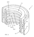
figure 1 est une vue en coupe axiale en perspective d'une boîte de peinture fermée par un couvercle équipé d'un joint d'étanchéité selon l'invention, à l'état introduit du corps du moyen d'agitation à travers le couvercle et ledit joint d'étanchéité ; - la
figure 2 est une vue en coupe axiale en perspective du joint d'étanchéité du couvercle de lafigure 1 . - En référence aux figures et comme rappelé ci-dessus, l'invention concerne un couvercle 2 de fermeture pour récipient 4 de liquide, de préférence pour boîte de peinture.
- Ledit couvercle 2 comprend un passage d'axe 20 permettant le passage à travers le couvercle 2 d'un corps allongé 30 d'un moyen d'agitation 3 destiné à être monté rotatif dans ledit passage d'axe 20 pour l'agitation dudit liquide. Ledit passage d'axe 20 comprend, d'une part, une partie 23 dite de réception du corps allongé 30 destinée à être traversée par le corps 30 allongé du moyen d'agitation 3, et, d'autre part, une partie dite de réception 21 de joint d'étanchéité 1, de diamètre interne supérieur au diamètre interne de la partie de réception 23 du corps 30 allongé. Ladite partie de réception 21 de joint d'étanchéité 1 loge un joint 1 d'étanchéité annulaire destiné à être traversé par ledit corps allongé 30 du moyen d'agitation 3. Ledit moyen d'agitation 3 permet de maintenir l'homogénéité du produit contenu dans le récipient, en particulier dans le cas d'un pot de peinture.
- Comme illustré à la
figure 1 , le couvercle 2 selon l'invention est destiné à la fermeture d'un pot ou autre récipient 4 de liquide. Ce couvercle 2 est un couvercle de précision qui présente un bec 25 verseur à obturateur 26 coulissant sollicité par un ressort 24 du type à épingle à cheveux. Cet obturateur 26 est commandé en déplacement par un levier 27 d'ouverture pivotant. Ledit couvercle 2 est manipulé par l'intermédiaire d'une poignée 28 de préhension. - Le récipient 4 et son couvercle 2 peuvent être logés dans une armoire de stockage disposant d'un ou plusieurs emplacements de stockage dudit récipient. Chaque emplacement est équipé d'un moyen d'actionnement du moyen d'agitation pour agiter le liquide par rotation du corps du moyen d'agitation. En particulier, ledit couvercle 2 peut être appliqué aux récipients dits suspendus au niveau de leur couvercle ou encore aux récipients posés dans une armoire d'agitation. Le couvercle est équipé de moyens de fixation au récipient 4. Avantageusement, le couvercle peut s'adapter à des boîtes de différents diamètres.
- Dans le cas des récipients posés, le couvercle 2 est mobile en translation par rapport au corps allongé 30, appelé axe, du moyen d'agitation 3, ce qui permet de s'adapter à des boîtes de différentes profondeurs, correspondant à des contenances par exemple de 0, 5 L et de 1 L.
- Dans l'exemple illustré à la
figure 1 , ledit couvercle 2 est équipé dudit moyen d'agitation 3 dont le corps allongé 30, tel que tige, est monté rotatif à travers le passage d'axe 20 du couvercle 2 et le joint d'étanchéité 1. Ledit corps allongé 30 est équipé à, ou au voisinage de, une extrémité, d'au moins un organe d'agitation 31 tel que pale et à, ou au voisinage de, l'extrémité opposée, d'une partie de prise 32 pour l'entrainement en rotation dudit corps allongé 30 rotatif du moyen d'agitation 3. Ladite partie de prise peut être soit une fourchette d'entraînement pour les boîtes dites posées, soit un pignon d'entraînement pour les boîtes dites suspendues. En particulier, dans l'exemple illustré à lafigure 1 , l'axe 30 porte une pale d'agitation 31 dont l'entraînement en rotation par l'intermédiaire du corps rotatif du moyen d'agitation permet l'agitation de la peinture contenue dans le pot. - De manière caractéristique à l'invention, la face périphérique interne dudit joint 1 d'étanchéité annulaire comprend une lèvre hélicoïdale 120.
- Autrement dit, le joint d'étanchéité 1 est positionné dans un logement 21 ménagé dans le passage d'axe 20, ledit logement 21 dudit joint étant coaxial au passage d'axe 20 et situé côté face inférieure, c'est-à-dire côté face orientée vers la face intérieure du récipient ou face opposée à la face supérieure dudit couvercle équipée du mécanisme d'obturation du bec verseur. En particulier, le logement 21 est formé par un épaulement dans le passage d'axe 20 de sorte que ledit logement débouche côté face inférieure du couvercle, ce qui permet une introduction et une extraction du joint par rapport à son logement depuis la face inférieure du couvercle.
- Le diamètre intérieur dudit joint annulaire 1, pris au niveau de la ligne sommet du filet, qui assure un léger serrage sur le corps allongé 30 du moyen d'agitation 3, est de préférence sensiblement inférieur au diamètre intérieur de la paroi de la partie 23 du passage d'axe 20 destinée au guidage en rotation avec jeu du corps allongé 30 du moyen d'agitation 3.
- Le joint annulaire 1 est un joint à deux parois périphériques 10, 11 reliées l'une à l'autre par une liaison souple 101. Lesdites parois dites respectivement interne 11 et externe 10, sensiblement coaxiales, sont écartées l'une de l'autre et reliées l'une à l'autre par une liaison souple 101 de type pont s'étendant, de préférence, à mi-hauteur desdites parois, dans le plan circonférentiel médian desdites parois.
- La liaison souple 101 de type pont forme une plateforme circulaire reliant lesdites parois entre elles. La double paroi présente en coupe transversale une forme en H.
- La liaison souple 101, déformable élastiquement, permet un bon centrage du corps allongé 30 de moyen d'agitation 3 à travers le joint 1 et le passage d'axe 20. En particulier, ladite liaison souple 101 permet l'auto-alignement entre le passage d'axe 20, ou palier, du couvercle 2 et la lèvre hélicoïdale 120 du joint d'étanchéité 1 lors de l'introduction du corps allongé 30 du moyen de d'agitation 3 à travers le passage d'axe 20 et le joint d'étanchéité 1.
- La liaison souple 101, permet de plus la dissociation des parois externe 10 et interne 11 qui ont des fonctions différentes. La paroi 10 a pour fonction le maintien par serrage à force du joint 1 dans son logement 21. La paroi 11 a pour fonction l'étanchéité par serrage léger sur le corps allongé 30 du moyen d'agitation 3.
- Comme illustré plus particulièrement à la
figure 2 , la lèvre hélicoïdale 120 comprend une pluralité de spires 121, 122, 123, 124 formant le filet hélicoïdal de la lèvre hélicoïdale 120 du joint d'étanchéité . - Les spires 121, 122, 123, 124 sont espacées axialement les unes des autres pour délimiter entre elles une gorge 12 en hélice. Ainsi, un liquide qui se serait introduit entre le joint 1 et le corps allongé 30 du moyen d'agitation 3 s'écoule dans ladite gorge 2 et retombe par gravité dans le pot de peinture 4 en parcourant ledit chemin en hélice.
- Le refoulement dudit liquide éventuellement monté dans la gorge en hélice 12 est également amélioré par la rotation du moyen d'agitation 3. L'orientation de la lèvre hélicoïdale 120 est définie en fonction du sens de rotation du corps allongé 30 du moyen d'agitation pour participer au refoulement dudit liquide vers l'intérieur du récipient. Lorsque le corps allongé 30 du moyen d'agitation 3 est destiné à être tourné en sens horaire, le filet hélicoïdal correspond à un filetage à droite. A l'inverse, lorsque le corps allongé 30 est destiné à être tourné en sens anti-horaire, le filet hélicoïdal correspond à un filetage à gauche. On entend par filetage à droite, respectivement à gauche, un filet ou filetage qui, dans la vue axiale, recule en tournant dans le sens horaire, respectivement dans le sens anti-horaire.
- La face périphérique interne dudit joint 1 d'étanchéité comprend également une lèvre d'étanchéité circulaire 13 située à proximité de la face d'ouverture dite supérieure du joint 1 d'étanchéité annulaire opposée à celle, dite inférieure, destinée à être orientée côté récipient 4. Autrement dit, ladite lèvre d'étanchéité circulaire 13 est située en partie supérieure du joint 1, à l'état monté dudit joint 1 dans le couvercle 2 qui ferme le récipient 4.
- Cette lèvre circulaire 13 réalise la fermeture de la gorge 12 formée par la lèvre hélicoïdale 120 en partie supérieure. Elle permet ainsi d'assurer l'étanchéité statique aux vapeurs de solvant ainsi qu'aux liquides.
- Ledit joint 1 d'étanchéité annulaire est réalisé en un matériau thermoplastique, tel qu'un élastomère thermoplastique.
- La présente invention n'est nullement limitée aux modes de réalisation décrits et représentés, mais l'homme du métier saura y apporter toute variante conforme à son esprit.
Claims (9)
- Couvercle (2) de fermeture pour récipient (4) de liquide, ledit couvercle comprenant un passage d'axe (20) permettant le passage à travers le couvercle (2) d'un corps allongé (30) d'un moyen d'agitation (3) destiné à être monté rotatif dans ledit passage d'axe (20), ledit passage d'axe (20) comprenant une partie dite de réception (21) logeant un joint (1) d'étanchéité annulaire destiné à être traversé par ledit corps allongé (30) du moyen d'agitation (3),
caractérisé en ce que la face périphérique interne dudit joint (1) d'étanchéité annulaire comprend une lèvre hélicoïdale (120),
et en ce que la face périphérique interne dudit joint (1) d'étanchéité comprend également une lèvre d'étanchéité circulaire (13) située à proximité de la face d'ouverture du joint (1) d'étanchéité annulaire opposée à celle destinée à être orientée côté récipient (4). - Couvercle (2) selon la revendication 1, caractérisé en ce que le joint annulaire (1) est un joint à deux parois périphériques (10, 11) reliées l'une à l'autre par rapport à une liaison souple.
- Couvercle (2) selon la revendication 2, caractérisé en ce que lesdites parois dites respectivement interne (11) et externe (10), sensiblement coaxiales, sont écartées l'une de l'autre et reliées l'une à l'autre par une liaison souple (101) de type pont s'étendant, de préférence, à mi-hauteur desdites parois, dans le plan circonférentiel médian desdites parois.
- Couvercle (2) selon l'une des revendications précédentes, caractérisé en ce que la lèvre hélicoïdale (120) comprend une pluralité de spires (121, 122, 123, 124).
- Couvercle (2) selon la revendication 4, caractérisé en ce que les spires (121, 122, 123, 124) sont espacées axialement les unes des autres pour délimiter entre elles une gorge (12) en hélice.
- Couvercle (2) selon la revendication 5, caractérisé en ce que l'orientation des spires (121, 122, 123, 124) du filet hélicoïdal est choisie de telle sorte que, pour un sens de rotation donné du moyen d'agitation, un éventuel liquide présent dans la gorge en hélice, délimitée entre les spires, est refoulé dans le récipient par rotation dudit moyen d'agitation.
- Couvercle (2) selon l'une des revendications précédentes, caractérisé en ce que ledit joint (1) d'étanchéité annulaire est réalisé en un matériau thermoplastique, tel qu'un élastomère thermoplastique.
- Couvercle (2) selon l'une des revendications précédentes, caractérisé en ce que ledit couvercle (2) est équipé dudit moyen d'agitation (3) dont le corps allongé (30), tel que tige, est monté rotatif à travers le passage d'axe (20) du couvercle (2) et le joint d'étanchéité (1).
- Récipient (4) de liquide, de préférence de peinture, équipé d'un couvercle de fermeture (2), caractérisé en ce que ledit couvercle (2) est conforme à l'une des revendications précédentes.
Priority Applications (1)
| Application Number | Priority Date | Filing Date | Title |
|---|---|---|---|
| PL11725168T PL2576038T3 (pl) | 2010-06-07 | 2011-05-13 | Pokrywka zamykająca do pojemnika wyposażonego w uszczelkę |
Applications Claiming Priority (2)
| Application Number | Priority Date | Filing Date | Title |
|---|---|---|---|
| FR1054451A FR2960863B1 (fr) | 2010-06-07 | 2010-06-07 | Couvercle de fermeture pour recipient equipe d'un joint d'etancheite |
| PCT/FR2011/051077 WO2011154629A1 (fr) | 2010-06-07 | 2011-05-13 | Couvercle de fermeture pour recipient equipe d'un joint d'etancheite |
Publications (2)
| Publication Number | Publication Date |
|---|---|
| EP2576038A1 EP2576038A1 (fr) | 2013-04-10 |
| EP2576038B1 true EP2576038B1 (fr) | 2014-07-02 |
Family
ID=43482808
Family Applications (1)
| Application Number | Title | Priority Date | Filing Date |
|---|---|---|---|
| EP11725168.6A Active EP2576038B1 (fr) | 2010-06-07 | 2011-05-13 | Couvercle de fermeture pour recipient equipe d'un joint d'etancheite |
Country Status (6)
| Country | Link |
|---|---|
| US (1) | US9770697B2 (fr) |
| EP (1) | EP2576038B1 (fr) |
| CN (1) | CN102933291B (fr) |
| FR (1) | FR2960863B1 (fr) |
| PL (1) | PL2576038T3 (fr) |
| WO (1) | WO2011154629A1 (fr) |
Cited By (8)
| Publication number | Priority date | Publication date | Assignee | Title |
|---|---|---|---|---|
| DE102023132609A1 (de) * | 2023-11-22 | 2025-05-22 | Gallena Müller IP GbR (vertretungsberechtigter Gesellschafter: Dr. Michael Gallena, 97337 Dettelbach) | Vorrichtung zum Lagern und/oder Applizieren und/oder Ausgeben und/oder Mischen von mindestens einer Farbe |
| DE102023132601A1 (de) * | 2023-11-22 | 2025-05-22 | Gallena Müller IP GbR (vertretungsberechtigter Gesellschafter: Dr. Michael Gallena, 97337 Dettelbach) | Vorrichtung und Verfahren zum Lagern und/oder Applizieren und/oder Ausgeben und/oder Mischen von mindestens einer Farbe |
| DE102023132608A1 (de) * | 2023-11-22 | 2025-05-22 | Gallena Müller IP GbR (vertretungsberechtigter Gesellschafter: Dr. Michael Gallena, 97337 Dettelbach) | Vorrichtung zum Lagern und/oder Applizieren und/oder Ausgeben und/oder Mischen von mindestens einer Farbe |
| DE102023132602A1 (de) * | 2023-11-22 | 2025-05-22 | Gallena Müller IP GbR (vertretungsberechtigter Gesellschafter: Dr. Michael Gallena, 97337 Dettelbach) | Vorrichtung und Verfahren zum Lagern und/oder Applizieren und/oder Ausgeben und/oder Mischen von mindestens einer Farbe |
| DE102023132606A1 (de) * | 2023-11-22 | 2025-05-22 | Gallena Müller IP GbR (vertretungsberechtigter Gesellschafter: Dr. Michael Gallena, 97337 Dettelbach) | Vorrichtung und Verfahren zum Lagern und/oder Applizieren und/oder Ausgeben und/oder Mischen von mindestens einer Farbe |
| DE102023132603A1 (de) * | 2023-11-22 | 2025-05-22 | Gallena Müller IP GbR (vertretungsberechtigter Gesellschafter: Dr. Michael Gallena, 97337 Dettelbach) | Vorrichtung zum Lagern und/oder Applizieren und/oder Ausgeben und/oder Mischen von mindestens einer Farbe |
| DE102023132605A1 (de) * | 2023-11-22 | 2025-05-22 | Gallena Müller IP GbR (vertretungsberechtigter Gesellschafter: Dr. Michael Gallena, 97337 Dettelbach) | Vorrichtung und Verfahren zum Lagern und/oder Applizieren und/oder Ausgeben und/oder Mischen von mindestens einer Farbe |
| WO2025109120A1 (fr) | 2023-11-22 | 2025-05-30 | Gallena Müller Ip Gbr, - | Dispositif et procédé de stockage et/ou d'application et/ou de distribution et/ou de mélange d'au moins une peinture |
Families Citing this family (9)
| Publication number | Priority date | Publication date | Assignee | Title |
|---|---|---|---|---|
| FR2997025A1 (fr) * | 2012-10-23 | 2014-04-25 | Aeml | Couvercle agitateur et systeme utilisant le couvercle agitateur |
| US9038674B2 (en) * | 2013-06-14 | 2015-05-26 | Sps Lid Technology Ii, Llc | Paint can cover assembly with paint return port |
| MX2019000862A (es) * | 2016-07-20 | 2019-06-20 | Blix Ltd | Recipiente de preparacion de alimentos de un solo uso montaje, sistema y metodo. |
| CA3181327A1 (fr) | 2016-11-10 | 2018-05-17 | Medisca Pharmaceutique Inc. | Methodes et systemes de melange pharmaceutique |
| WO2019016790A1 (fr) | 2017-07-18 | 2019-01-24 | Blix Ltd. | Ensembles récipients de préparation d'aliments à usage unique, systèmes et procédés associés |
| CN108757942A (zh) * | 2018-06-28 | 2018-11-06 | 无锡沃尔福汽车技术有限公司 | 一种用于密封旋转类部件的密封结构 |
| CN111266072A (zh) * | 2019-12-05 | 2020-06-12 | 吕炎 | 一种多功能立式反应釜 |
| CN114136066B (zh) * | 2021-12-13 | 2023-04-07 | 安徽天邦生物技术有限公司 | 一种仔猪养殖用发酵饲料干化装置及其实施方法 |
| US20240270459A1 (en) * | 2023-02-15 | 2024-08-15 | Lawrence Ozobu | Painting Supplies Storage Device And Method Of Use |
Family Cites Families (40)
| Publication number | Priority date | Publication date | Assignee | Title |
|---|---|---|---|---|
| GB307581A (en) * | 1927-01-24 | 1929-03-14 | Schering Kahlbaum Ag | Improvements in or relating to stuffing boxes and the like for preventing the escapeof fluid under pressure |
| GB657964A (en) * | 1949-04-07 | 1951-10-03 | Angus George Co Ltd | Improvements relating to bushes for sealing rotating shafts |
| US2793012A (en) * | 1954-05-06 | 1957-05-21 | Wallace P Wolf | Sediment stirrer |
| US3162338A (en) * | 1962-07-25 | 1964-12-22 | Nicholas T Grubelic | Closure device for liquid containers such as paint cans |
| BE638867A (fr) * | 1962-11-28 | |||
| US3228342A (en) * | 1963-11-13 | 1966-01-11 | Barnes Mfg Co | Impeller seal for a centrifugal pump |
| US3738760A (en) * | 1971-10-13 | 1973-06-12 | Plastic Kote Co | Paint touch-up container |
| US3894723A (en) * | 1972-07-10 | 1975-07-15 | Murray A Sanders | Removable agitator |
| GB1415095A (en) * | 1973-01-23 | 1975-11-26 | Decca Ltd | Sealing assemblies |
| US3901167A (en) * | 1974-06-06 | 1975-08-26 | Dale C Reese | Waterproof, airtight closure |
| US3915351A (en) * | 1974-08-19 | 1975-10-28 | Alexander Enrico Kiralfy | Cordless electrically operated centrifugal pump |
| NL168311C (nl) * | 1978-03-01 | 1982-03-16 | Neratoom | Afdichtende doorvoer. |
| NL168596C (nl) * | 1978-03-01 | 1982-04-16 | Neratoom | Afdichtende doorvoer voor een door een wand van een huis gevoerd, om een as roteerbaar lichaam. |
| JPS5748766Y2 (fr) * | 1979-09-17 | 1982-10-26 | ||
| DE3114436A1 (de) * | 1980-04-19 | 1982-03-04 | Fisons Ltd., London | "verschlusskappe fuer einen behaelter" |
| IT1186652B (it) * | 1982-01-15 | 1987-12-04 | Ceramiche Di Riosecco Dei Figl | Meccanismo di chiusura rapida ed ermetica per contenitori in ceramica |
| US4483623A (en) * | 1983-04-15 | 1984-11-20 | Corning Glass Works | Magnetic stirring apparatus |
| US4512666A (en) * | 1984-02-24 | 1985-04-23 | Corning Glass Works | Adjustable height magnetic stirrer |
| EP0333111B1 (fr) * | 1988-03-14 | 1995-08-09 | Kanegafuchi Kagaku Kogyo Kabushiki Kaisha | Mélangeur continu pour deux liquides |
| US4880146A (en) * | 1988-06-08 | 1989-11-14 | Hudgins J S | Drop dispenser which automatically stirs the contents of the dispenser when the cap is removed |
| US4905862A (en) * | 1988-12-05 | 1990-03-06 | American Flange & Manufacturing Co. Inc. | Protective closure |
| US4917520A (en) * | 1989-01-04 | 1990-04-17 | Ginny Reid | Applicator brush |
| US5167449A (en) * | 1991-12-12 | 1992-12-01 | Corning Incorporated | Paddle shaft assembly with adjustable-pitch paddles |
| US5172992A (en) * | 1992-03-09 | 1992-12-22 | Risdon Corporation | Mascara container with stirrer |
| US5251979A (en) * | 1992-07-24 | 1993-10-12 | Larsen Paul R | Paint can cover with mixer |
| FR2707180B1 (fr) * | 1993-07-05 | 1995-09-29 | Fas | Couvercle agitateur pour machine d'agitation de peinture. |
| US5450368A (en) * | 1993-12-28 | 1995-09-12 | Three Bond Co., Ltd. | Two liquid type mixer |
| IT1283273B1 (it) * | 1996-03-18 | 1998-04-16 | Tecmec S R L | Struttura di coperchio miscelatore,particolarmente studiato per barattoli di vernici e simili. |
| FR2751563B1 (fr) | 1996-07-23 | 1998-09-25 | Fas | Couvercle agitateur pour boite de teinte sur les machines d'agitation de peinture |
| US6698934B2 (en) * | 2002-04-29 | 2004-03-02 | Conocophillips Company | Agitator drive |
| DK1551541T3 (da) * | 2002-10-15 | 2008-12-08 | Medic Tools Ag | Engangsblande- og homogeniseringsindretning |
| CN2702129Y (zh) * | 2004-06-17 | 2005-05-25 | 陈乙强 | 碳纤维增强聚四氟乙烯膜层包覆油封 |
| DE102004040105A1 (de) * | 2004-08-18 | 2006-03-09 | Carl Freudenberg Kg | Dichtring mit Rückfördernuten deren Steigung in Richtung der Umgebung zunimmt |
| US7823736B1 (en) * | 2005-03-30 | 2010-11-02 | Rexam Closure Systems Inc. | Plastic closure having mounting ring for containers |
| US7946752B2 (en) * | 2005-09-06 | 2011-05-24 | Sharron Swartz | Mug with stirring mechanism |
| US7497348B2 (en) * | 2005-12-15 | 2009-03-03 | Red Devil Equipment Company | Adapter for paint mixers |
| EP2055372B1 (fr) * | 2007-11-01 | 2010-09-15 | Mettler-Toledo AG | Unité de mélangeur comprenant un adaptateur |
| DE102008010427B4 (de) | 2008-02-21 | 2010-05-12 | Sartorius Stedim Biotech Gmbh | Bioreaktor |
| EP2179788B9 (fr) * | 2008-10-24 | 2012-02-08 | Biazzi Sa | Appareillage à cuve d'agitation |
| US8408418B2 (en) * | 2010-11-05 | 2013-04-02 | Michael D. Stolzman | Drum cover with center support |
-
2010
- 2010-06-07 FR FR1054451A patent/FR2960863B1/fr not_active Expired - Fee Related
-
2011
- 2011-05-13 EP EP11725168.6A patent/EP2576038B1/fr active Active
- 2011-05-13 US US13/699,895 patent/US9770697B2/en active Active
- 2011-05-13 WO PCT/FR2011/051077 patent/WO2011154629A1/fr not_active Ceased
- 2011-05-13 CN CN201180028388.0A patent/CN102933291B/zh active Active
- 2011-05-13 PL PL11725168T patent/PL2576038T3/pl unknown
Cited By (11)
| Publication number | Priority date | Publication date | Assignee | Title |
|---|---|---|---|---|
| DE102023132609A1 (de) * | 2023-11-22 | 2025-05-22 | Gallena Müller IP GbR (vertretungsberechtigter Gesellschafter: Dr. Michael Gallena, 97337 Dettelbach) | Vorrichtung zum Lagern und/oder Applizieren und/oder Ausgeben und/oder Mischen von mindestens einer Farbe |
| DE102023132601A1 (de) * | 2023-11-22 | 2025-05-22 | Gallena Müller IP GbR (vertretungsberechtigter Gesellschafter: Dr. Michael Gallena, 97337 Dettelbach) | Vorrichtung und Verfahren zum Lagern und/oder Applizieren und/oder Ausgeben und/oder Mischen von mindestens einer Farbe |
| DE102023132608A1 (de) * | 2023-11-22 | 2025-05-22 | Gallena Müller IP GbR (vertretungsberechtigter Gesellschafter: Dr. Michael Gallena, 97337 Dettelbach) | Vorrichtung zum Lagern und/oder Applizieren und/oder Ausgeben und/oder Mischen von mindestens einer Farbe |
| DE102023132602A1 (de) * | 2023-11-22 | 2025-05-22 | Gallena Müller IP GbR (vertretungsberechtigter Gesellschafter: Dr. Michael Gallena, 97337 Dettelbach) | Vorrichtung und Verfahren zum Lagern und/oder Applizieren und/oder Ausgeben und/oder Mischen von mindestens einer Farbe |
| DE102023132606A1 (de) * | 2023-11-22 | 2025-05-22 | Gallena Müller IP GbR (vertretungsberechtigter Gesellschafter: Dr. Michael Gallena, 97337 Dettelbach) | Vorrichtung und Verfahren zum Lagern und/oder Applizieren und/oder Ausgeben und/oder Mischen von mindestens einer Farbe |
| DE102023132603A1 (de) * | 2023-11-22 | 2025-05-22 | Gallena Müller IP GbR (vertretungsberechtigter Gesellschafter: Dr. Michael Gallena, 97337 Dettelbach) | Vorrichtung zum Lagern und/oder Applizieren und/oder Ausgeben und/oder Mischen von mindestens einer Farbe |
| DE102023132605A1 (de) * | 2023-11-22 | 2025-05-22 | Gallena Müller IP GbR (vertretungsberechtigter Gesellschafter: Dr. Michael Gallena, 97337 Dettelbach) | Vorrichtung und Verfahren zum Lagern und/oder Applizieren und/oder Ausgeben und/oder Mischen von mindestens einer Farbe |
| WO2025109120A1 (fr) | 2023-11-22 | 2025-05-30 | Gallena Müller Ip Gbr, - | Dispositif et procédé de stockage et/ou d'application et/ou de distribution et/ou de mélange d'au moins une peinture |
| WO2025109122A1 (fr) | 2023-11-22 | 2025-05-30 | Gallena Müller Ip Gbr | Dispositif et procédé de stockage et/ou d'application et/ou de distribution et/ou de mélange d'au moins une peinture |
| WO2025109121A1 (fr) | 2023-11-22 | 2025-05-30 | Gallena Müller Ip Gbr | Appareil de stockage et/ou d'application et/ou de distribution et/ou de mélange d'au moins une peinture |
| DE102023132609B4 (de) * | 2023-11-22 | 2025-10-16 | Gallena Müller IP GbR (vertretungsberechtigter Gesellschafter: Dr. Michael Gallena, 97337 Dettelbach) | Vorrichtung zum Lagern und/oder Applizieren und/oder Ausgeben und/oder Mischen von mindestens einer Farbe |
Also Published As
| Publication number | Publication date |
|---|---|
| CN102933291A (zh) | 2013-02-13 |
| EP2576038A1 (fr) | 2013-04-10 |
| FR2960863B1 (fr) | 2012-07-13 |
| PL2576038T3 (pl) | 2014-12-31 |
| FR2960863A1 (fr) | 2011-12-09 |
| CN102933291B (zh) | 2015-03-11 |
| US20130121105A1 (en) | 2013-05-16 |
| US9770697B2 (en) | 2017-09-26 |
| WO2011154629A1 (fr) | 2011-12-15 |
Similar Documents
| Publication | Publication Date | Title |
|---|---|---|
| EP2576038B1 (fr) | Couvercle de fermeture pour recipient equipe d'un joint d'etancheite | |
| EP0538094B1 (fr) | Récipient métallique à ouverture partielle par rupture d'une ligne de moindre résistance | |
| EP0761558B1 (fr) | Dispositif de bouchage d'un récipient et de distribution du produit qu'il contient | |
| FR3101066A1 (fr) | Récipient à contenant interne en verre et méthode d’assemblage du récipient par utilisation d’un insert d’espacement et verrouillage | |
| FR2694920A1 (fr) | Dispositif pour conserver séparés l'un de l'autre au moins deux produits et pour effectuer leur mélange à un instant souhaité. | |
| FR2792298A1 (fr) | Dispositif pour le melange extemporane d'au moins deux produits dont un est notamment une poudre | |
| WO2014128428A1 (fr) | Fût étanche de transport de produit chimique pulvérulent | |
| FR2751941A1 (fr) | Dispositif pour le conditionnement separe de deux composants, leur melange et la distribution du melange ainsi obtenu | |
| FR2892097A1 (fr) | Couvercle a usages multiples, notamment pour des liquides, notamment pour pot de peinture. | |
| FR2954754A1 (fr) | Capsule distributrice pour flacon de produit de consistance liquide ou visqueuse et flacon muni d'une telle capsule | |
| FR2890940A1 (fr) | Dispositif de remplissage en liquide de recipient aerosol, installation de remplissage apte a recevoir un tel dispositif et recipient aerosol equipe d'un tel dispositif de remplissage | |
| EP1317384B1 (fr) | Verseur a verrouillage ameliore et capsule munie dudit verseur | |
| FR3126404A1 (fr) | Recipient a couvercle a verrouillage magnetique automatique | |
| FR2783510A1 (fr) | Capsule de bouchage d'un recipient de produit liquide | |
| FR3062378A1 (fr) | Recipient de peinture comportant un organe d'obturation optimise | |
| EP4147985B1 (fr) | Dispositif de stockage d'un liquide comportant un contenant et un bouchon restant solidaire au contenant | |
| EP0648683A1 (fr) | Dispositif de bouchage d'un récipient muni d'un goulot, du type flacon ou pot | |
| EP0739826B1 (fr) | Dispositif de fermeture pour une ouverture latérale de distribution escamotable axialement | |
| EP4297910B1 (fr) | Reservoir et distributeur de produit fluide | |
| WO2006081928A1 (fr) | Dispositif de fermeture de distribution destine a un recipient | |
| FR3062379A1 (fr) | Recipient de peinture comportant une valve d'admission d'air optimisee | |
| FR3158100A1 (fr) | Ensemble de conditionnement de produit cosmétique, dispositif de conditionnement et de distribution, recharge et procédé de montage associé | |
| FR3159299A1 (fr) | Dispositif d'application d'un bâton de produit cosmetique | |
| EP0304367A1 (fr) | Flacon comportant un bouchon rotatif | |
| FR3158102A1 (fr) | Recharge destinée à contenir un produit cosmétique fluide, nécessaire, procédé de fabrication et procédé d’assemblage associé |
Legal Events
| Date | Code | Title | Description |
|---|---|---|---|
| PUAI | Public reference made under article 153(3) epc to a published international application that has entered the european phase |
Free format text: ORIGINAL CODE: 0009012 |
|
| 17P | Request for examination filed |
Effective date: 20121119 |
|
| AK | Designated contracting states |
Kind code of ref document: A1 Designated state(s): AL AT BE BG CH CY CZ DE DK EE ES FI FR GB GR HR HU IE IS IT LI LT LU LV MC MK MT NL NO PL PT RO RS SE SI SK SM TR |
|
| RIN1 | Information on inventor provided before grant (corrected) |
Inventor name: SAINT, PATRICK Inventor name: DENIZE, CYRIL |
|
| DAX | Request for extension of the european patent (deleted) | ||
| 17Q | First examination report despatched |
Effective date: 20130906 |
|
| REG | Reference to a national code |
Ref country code: DE Ref legal event code: R079 Ref document number: 602011008138 Country of ref document: DE Free format text: PREVIOUS MAIN CLASS: B01F0007160000 Ipc: B01F0007000000 |
|
| GRAP | Despatch of communication of intention to grant a patent |
Free format text: ORIGINAL CODE: EPIDOSNIGR1 |
|
| RIC1 | Information provided on ipc code assigned before grant |
Ipc: B01F 7/16 20060101ALI20140304BHEP Ipc: B01F 15/00 20060101ALI20140304BHEP Ipc: F16J 15/16 20060101ALI20140304BHEP Ipc: B01F 7/00 20060101AFI20140304BHEP Ipc: F16J 15/32 20060101ALI20140304BHEP |
|
| INTG | Intention to grant announced |
Effective date: 20140325 |
|
| GRAS | Grant fee paid |
Free format text: ORIGINAL CODE: EPIDOSNIGR3 |
|
| GRAA | (expected) grant |
Free format text: ORIGINAL CODE: 0009210 |
|
| AK | Designated contracting states |
Kind code of ref document: B1 Designated state(s): AL AT BE BG CH CY CZ DE DK EE ES FI FR GB GR HR HU IE IS IT LI LT LU LV MC MK MT NL NO PL PT RO RS SE SI SK SM TR |
|
| REG | Reference to a national code |
Ref country code: GB Ref legal event code: FG4D Free format text: NOT ENGLISH |
|
| REG | Reference to a national code |
Ref country code: CH Ref legal event code: EP Ref country code: AT Ref legal event code: REF Ref document number: 675594 Country of ref document: AT Kind code of ref document: T Effective date: 20140715 |
|
| REG | Reference to a national code |
Ref country code: IE Ref legal event code: FG4D Free format text: LANGUAGE OF EP DOCUMENT: FRENCH |
|
| REG | Reference to a national code |
Ref country code: DE Ref legal event code: R096 Ref document number: 602011008138 Country of ref document: DE Effective date: 20140814 |
|
| REG | Reference to a national code |
Ref country code: AT Ref legal event code: MK05 Ref document number: 675594 Country of ref document: AT Kind code of ref document: T Effective date: 20140702 |
|
| REG | Reference to a national code |
Ref country code: NL Ref legal event code: VDEP Effective date: 20140702 |
|
| REG | Reference to a national code |
Ref country code: LT Ref legal event code: MG4D |
|
| REG | Reference to a national code |
Ref country code: PL Ref legal event code: T3 |
|
| PG25 | Lapsed in a contracting state [announced via postgrant information from national office to epo] |
Ref country code: LT Free format text: LAPSE BECAUSE OF FAILURE TO SUBMIT A TRANSLATION OF THE DESCRIPTION OR TO PAY THE FEE WITHIN THE PRESCRIBED TIME-LIMIT Effective date: 20140702 Ref country code: PT Free format text: LAPSE BECAUSE OF FAILURE TO SUBMIT A TRANSLATION OF THE DESCRIPTION OR TO PAY THE FEE WITHIN THE PRESCRIBED TIME-LIMIT Effective date: 20141103 Ref country code: ES Free format text: LAPSE BECAUSE OF FAILURE TO SUBMIT A TRANSLATION OF THE DESCRIPTION OR TO PAY THE FEE WITHIN THE PRESCRIBED TIME-LIMIT Effective date: 20140702 Ref country code: SE Free format text: LAPSE BECAUSE OF FAILURE TO SUBMIT A TRANSLATION OF THE DESCRIPTION OR TO PAY THE FEE WITHIN THE PRESCRIBED TIME-LIMIT Effective date: 20140702 Ref country code: FI Free format text: LAPSE BECAUSE OF FAILURE TO SUBMIT A TRANSLATION OF THE DESCRIPTION OR TO PAY THE FEE WITHIN THE PRESCRIBED TIME-LIMIT Effective date: 20140702 Ref country code: NO Free format text: LAPSE BECAUSE OF FAILURE TO SUBMIT A TRANSLATION OF THE DESCRIPTION OR TO PAY THE FEE WITHIN THE PRESCRIBED TIME-LIMIT Effective date: 20141002 Ref country code: BG Free format text: LAPSE BECAUSE OF FAILURE TO SUBMIT A TRANSLATION OF THE DESCRIPTION OR TO PAY THE FEE WITHIN THE PRESCRIBED TIME-LIMIT Effective date: 20141002 Ref country code: CZ Free format text: LAPSE BECAUSE OF FAILURE TO SUBMIT A TRANSLATION OF THE DESCRIPTION OR TO PAY THE FEE WITHIN THE PRESCRIBED TIME-LIMIT Effective date: 20140702 |
|
| PG25 | Lapsed in a contracting state [announced via postgrant information from national office to epo] |
Ref country code: NL Free format text: LAPSE BECAUSE OF FAILURE TO SUBMIT A TRANSLATION OF THE DESCRIPTION OR TO PAY THE FEE WITHIN THE PRESCRIBED TIME-LIMIT Effective date: 20140702 Ref country code: RS Free format text: LAPSE BECAUSE OF FAILURE TO SUBMIT A TRANSLATION OF THE DESCRIPTION OR TO PAY THE FEE WITHIN THE PRESCRIBED TIME-LIMIT Effective date: 20140702 Ref country code: CY Free format text: LAPSE BECAUSE OF FAILURE TO SUBMIT A TRANSLATION OF THE DESCRIPTION OR TO PAY THE FEE WITHIN THE PRESCRIBED TIME-LIMIT Effective date: 20140702 Ref country code: HR Free format text: LAPSE BECAUSE OF FAILURE TO SUBMIT A TRANSLATION OF THE DESCRIPTION OR TO PAY THE FEE WITHIN THE PRESCRIBED TIME-LIMIT Effective date: 20140702 Ref country code: IS Free format text: LAPSE BECAUSE OF FAILURE TO SUBMIT A TRANSLATION OF THE DESCRIPTION OR TO PAY THE FEE WITHIN THE PRESCRIBED TIME-LIMIT Effective date: 20141102 Ref country code: AT Free format text: LAPSE BECAUSE OF FAILURE TO SUBMIT A TRANSLATION OF THE DESCRIPTION OR TO PAY THE FEE WITHIN THE PRESCRIBED TIME-LIMIT Effective date: 20140702 Ref country code: LV Free format text: LAPSE BECAUSE OF FAILURE TO SUBMIT A TRANSLATION OF THE DESCRIPTION OR TO PAY THE FEE WITHIN THE PRESCRIBED TIME-LIMIT Effective date: 20140702 |
|
| REG | Reference to a national code |
Ref country code: DE Ref legal event code: R097 Ref document number: 602011008138 Country of ref document: DE |
|
| PG25 | Lapsed in a contracting state [announced via postgrant information from national office to epo] |
Ref country code: DK Free format text: LAPSE BECAUSE OF FAILURE TO SUBMIT A TRANSLATION OF THE DESCRIPTION OR TO PAY THE FEE WITHIN THE PRESCRIBED TIME-LIMIT Effective date: 20140702 Ref country code: SK Free format text: LAPSE BECAUSE OF FAILURE TO SUBMIT A TRANSLATION OF THE DESCRIPTION OR TO PAY THE FEE WITHIN THE PRESCRIBED TIME-LIMIT Effective date: 20140702 Ref country code: EE Free format text: LAPSE BECAUSE OF FAILURE TO SUBMIT A TRANSLATION OF THE DESCRIPTION OR TO PAY THE FEE WITHIN THE PRESCRIBED TIME-LIMIT Effective date: 20140702 Ref country code: RO Free format text: LAPSE BECAUSE OF FAILURE TO SUBMIT A TRANSLATION OF THE DESCRIPTION OR TO PAY THE FEE WITHIN THE PRESCRIBED TIME-LIMIT Effective date: 20140702 |
|
| PLBE | No opposition filed within time limit |
Free format text: ORIGINAL CODE: 0009261 |
|
| STAA | Information on the status of an ep patent application or granted ep patent |
Free format text: STATUS: NO OPPOSITION FILED WITHIN TIME LIMIT |
|
| 26N | No opposition filed |
Effective date: 20150407 |
|
| PG25 | Lapsed in a contracting state [announced via postgrant information from national office to epo] |
Ref country code: SI Free format text: LAPSE BECAUSE OF FAILURE TO SUBMIT A TRANSLATION OF THE DESCRIPTION OR TO PAY THE FEE WITHIN THE PRESCRIBED TIME-LIMIT Effective date: 20140702 |
|
| REG | Reference to a national code |
Ref country code: CH Ref legal event code: PL |
|
| PG25 | Lapsed in a contracting state [announced via postgrant information from national office to epo] |
Ref country code: LI Free format text: LAPSE BECAUSE OF NON-PAYMENT OF DUE FEES Effective date: 20150531 Ref country code: MC Free format text: LAPSE BECAUSE OF FAILURE TO SUBMIT A TRANSLATION OF THE DESCRIPTION OR TO PAY THE FEE WITHIN THE PRESCRIBED TIME-LIMIT Effective date: 20140702 Ref country code: CH Free format text: LAPSE BECAUSE OF NON-PAYMENT OF DUE FEES Effective date: 20150531 Ref country code: LU Free format text: LAPSE BECAUSE OF FAILURE TO SUBMIT A TRANSLATION OF THE DESCRIPTION OR TO PAY THE FEE WITHIN THE PRESCRIBED TIME-LIMIT Effective date: 20150513 |
|
| REG | Reference to a national code |
Ref country code: IE Ref legal event code: MM4A |
|
| PG25 | Lapsed in a contracting state [announced via postgrant information from national office to epo] |
Ref country code: IE Free format text: LAPSE BECAUSE OF NON-PAYMENT OF DUE FEES Effective date: 20150513 |
|
| REG | Reference to a national code |
Ref country code: FR Ref legal event code: PLFP Year of fee payment: 6 |
|
| PG25 | Lapsed in a contracting state [announced via postgrant information from national office to epo] |
Ref country code: MT Free format text: LAPSE BECAUSE OF FAILURE TO SUBMIT A TRANSLATION OF THE DESCRIPTION OR TO PAY THE FEE WITHIN THE PRESCRIBED TIME-LIMIT Effective date: 20140702 |
|
| REG | Reference to a national code |
Ref country code: FR Ref legal event code: PLFP Year of fee payment: 7 |
|
| PG25 | Lapsed in a contracting state [announced via postgrant information from national office to epo] |
Ref country code: HU Free format text: LAPSE BECAUSE OF FAILURE TO SUBMIT A TRANSLATION OF THE DESCRIPTION OR TO PAY THE FEE WITHIN THE PRESCRIBED TIME-LIMIT; INVALID AB INITIO Effective date: 20110513 Ref country code: SM Free format text: LAPSE BECAUSE OF FAILURE TO SUBMIT A TRANSLATION OF THE DESCRIPTION OR TO PAY THE FEE WITHIN THE PRESCRIBED TIME-LIMIT Effective date: 20140702 |
|
| PG25 | Lapsed in a contracting state [announced via postgrant information from national office to epo] |
Ref country code: GR Free format text: LAPSE BECAUSE OF FAILURE TO SUBMIT A TRANSLATION OF THE DESCRIPTION OR TO PAY THE FEE WITHIN THE PRESCRIBED TIME-LIMIT Effective date: 20140702 |
|
| PG25 | Lapsed in a contracting state [announced via postgrant information from national office to epo] |
Ref country code: BE Free format text: LAPSE BECAUSE OF NON-PAYMENT OF DUE FEES Effective date: 20150531 |
|
| PG25 | Lapsed in a contracting state [announced via postgrant information from national office to epo] |
Ref country code: TR Free format text: LAPSE BECAUSE OF FAILURE TO SUBMIT A TRANSLATION OF THE DESCRIPTION OR TO PAY THE FEE WITHIN THE PRESCRIBED TIME-LIMIT Effective date: 20140702 |
|
| REG | Reference to a national code |
Ref country code: FR Ref legal event code: PLFP Year of fee payment: 8 |
|
| PG25 | Lapsed in a contracting state [announced via postgrant information from national office to epo] |
Ref country code: MK Free format text: LAPSE BECAUSE OF FAILURE TO SUBMIT A TRANSLATION OF THE DESCRIPTION OR TO PAY THE FEE WITHIN THE PRESCRIBED TIME-LIMIT Effective date: 20140702 |
|
| REG | Reference to a national code |
Ref country code: FR Ref legal event code: GC Effective date: 20180829 |
|
| PG25 | Lapsed in a contracting state [announced via postgrant information from national office to epo] |
Ref country code: AL Free format text: LAPSE BECAUSE OF FAILURE TO SUBMIT A TRANSLATION OF THE DESCRIPTION OR TO PAY THE FEE WITHIN THE PRESCRIBED TIME-LIMIT Effective date: 20140702 |
|
| REG | Reference to a national code |
Ref country code: DE Ref legal event code: R079 Ref document number: 602011008138 Country of ref document: DE Free format text: PREVIOUS MAIN CLASS: B01F0007000000 Ipc: B01F0027000000 |
|
| P01 | Opt-out of the competence of the unified patent court (upc) registered |
Effective date: 20230530 |
|
| PGFP | Annual fee paid to national office [announced via postgrant information from national office to epo] |
Ref country code: PL Payment date: 20250512 Year of fee payment: 15 Ref country code: DE Payment date: 20250521 Year of fee payment: 15 |
|
| PGFP | Annual fee paid to national office [announced via postgrant information from national office to epo] |
Ref country code: GB Payment date: 20250521 Year of fee payment: 15 |
|
| PGFP | Annual fee paid to national office [announced via postgrant information from national office to epo] |
Ref country code: IT Payment date: 20250527 Year of fee payment: 15 |
|
| PGFP | Annual fee paid to national office [announced via postgrant information from national office to epo] |
Ref country code: FR Payment date: 20250528 Year of fee payment: 15 |