EP2576082B1 - Procédé et appareil pour la commande d'une tête de couchage, et tête de couchage - Google Patents
Procédé et appareil pour la commande d'une tête de couchage, et tête de couchage Download PDFInfo
- Publication number
- EP2576082B1 EP2576082B1 EP10725224.9A EP10725224A EP2576082B1 EP 2576082 B1 EP2576082 B1 EP 2576082B1 EP 10725224 A EP10725224 A EP 10725224A EP 2576082 B1 EP2576082 B1 EP 2576082B1
- Authority
- EP
- European Patent Office
- Prior art keywords
- coating
- fibrous web
- actuators
- nip pressure
- coating head
- Prior art date
- Legal status (The legal status is an assumption and is not a legal conclusion. Google has not performed a legal analysis and makes no representation as to the accuracy of the status listed.)
- Not-in-force
Links
- 238000000576 coating method Methods 0.000 title claims description 123
- 239000011248 coating agent Substances 0.000 title claims description 122
- 238000000034 method Methods 0.000 title claims description 32
- 238000005259 measurement Methods 0.000 claims description 29
- 230000010355 oscillation Effects 0.000 claims description 14
- 239000000126 substance Substances 0.000 claims description 9
- 239000011247 coating layer Substances 0.000 claims description 6
- 125000004122 cyclic group Chemical group 0.000 description 13
- 238000009826 distribution Methods 0.000 description 6
- 238000012546 transfer Methods 0.000 description 6
- 230000000694 effects Effects 0.000 description 5
- 238000004422 calculation algorithm Methods 0.000 description 4
- 238000012544 monitoring process Methods 0.000 description 4
- 238000012545 processing Methods 0.000 description 4
- 238000012937 correction Methods 0.000 description 3
- 230000004044 response Effects 0.000 description 3
- 238000013459 approach Methods 0.000 description 2
- 230000008901 benefit Effects 0.000 description 2
- 238000009795 derivation Methods 0.000 description 2
- 239000012530 fluid Substances 0.000 description 2
- 238000004519 manufacturing process Methods 0.000 description 2
- 239000000463 material Substances 0.000 description 2
- 230000003534 oscillatory effect Effects 0.000 description 2
- 238000012935 Averaging Methods 0.000 description 1
- 229910001069 Ti alloy Inorganic materials 0.000 description 1
- 238000005299 abrasion Methods 0.000 description 1
- 230000003466 anti-cipated effect Effects 0.000 description 1
- 238000004364 calculation method Methods 0.000 description 1
- 230000008859 change Effects 0.000 description 1
- 238000004891 communication Methods 0.000 description 1
- 230000001447 compensatory effect Effects 0.000 description 1
- 239000002131 composite material Substances 0.000 description 1
- 238000010276 construction Methods 0.000 description 1
- 230000008878 coupling Effects 0.000 description 1
- 238000010168 coupling process Methods 0.000 description 1
- 238000005859 coupling reaction Methods 0.000 description 1
- 230000001934 delay Effects 0.000 description 1
- 238000001514 detection method Methods 0.000 description 1
- 238000006073 displacement reaction Methods 0.000 description 1
- 230000005489 elastic deformation Effects 0.000 description 1
- 230000005284 excitation Effects 0.000 description 1
- 238000007667 floating Methods 0.000 description 1
- 239000010410 layer Substances 0.000 description 1
- 230000007246 mechanism Effects 0.000 description 1
- 230000010363 phase shift Effects 0.000 description 1
- 238000007639 printing Methods 0.000 description 1
- 230000008569 process Effects 0.000 description 1
- 238000013139 quantization Methods 0.000 description 1
- 230000001172 regenerating effect Effects 0.000 description 1
- 238000005070 sampling Methods 0.000 description 1
- 230000007480 spreading Effects 0.000 description 1
- 238000003892 spreading Methods 0.000 description 1
Images

Classifications
-
- B—PERFORMING OPERATIONS; TRANSPORTING
- B05—SPRAYING OR ATOMISING IN GENERAL; APPLYING FLUENT MATERIALS TO SURFACES, IN GENERAL
- B05D—PROCESSES FOR APPLYING FLUENT MATERIALS TO SURFACES, IN GENERAL
- B05D1/00—Processes for applying liquids or other fluent materials
- B05D1/40—Distributing applied liquids or other fluent materials by members moving relatively to surface
-
- B—PERFORMING OPERATIONS; TRANSPORTING
- B05—SPRAYING OR ATOMISING IN GENERAL; APPLYING FLUENT MATERIALS TO SURFACES, IN GENERAL
- B05C—APPARATUS FOR APPLYING FLUENT MATERIALS TO SURFACES, IN GENERAL
- B05C11/00—Component parts, details or accessories not specifically provided for in groups B05C1/00 - B05C9/00
- B05C11/02—Apparatus for spreading or distributing liquids or other fluent materials already applied to a surface ; Controlling means therefor; Control of the thickness of a coating by spreading or distributing liquids or other fluent materials already applied to the coated surface
- B05C11/04—Apparatus for spreading or distributing liquids or other fluent materials already applied to a surface ; Controlling means therefor; Control of the thickness of a coating by spreading or distributing liquids or other fluent materials already applied to the coated surface with blades
- B05C11/041—Apparatus for spreading or distributing liquids or other fluent materials already applied to a surface ; Controlling means therefor; Control of the thickness of a coating by spreading or distributing liquids or other fluent materials already applied to the coated surface with blades characterised by means for positioning, loading, or deforming the blades
-
- B—PERFORMING OPERATIONS; TRANSPORTING
- B05—SPRAYING OR ATOMISING IN GENERAL; APPLYING FLUENT MATERIALS TO SURFACES, IN GENERAL
- B05C—APPARATUS FOR APPLYING FLUENT MATERIALS TO SURFACES, IN GENERAL
- B05C11/00—Component parts, details or accessories not specifically provided for in groups B05C1/00 - B05C9/00
- B05C11/02—Apparatus for spreading or distributing liquids or other fluent materials already applied to a surface ; Controlling means therefor; Control of the thickness of a coating by spreading or distributing liquids or other fluent materials already applied to the coated surface
- B05C11/04—Apparatus for spreading or distributing liquids or other fluent materials already applied to a surface ; Controlling means therefor; Control of the thickness of a coating by spreading or distributing liquids or other fluent materials already applied to the coated surface with blades
- B05C11/044—Apparatus for spreading or distributing liquids or other fluent materials already applied to a surface ; Controlling means therefor; Control of the thickness of a coating by spreading or distributing liquids or other fluent materials already applied to the coated surface with blades characterised by means for holding the blades
-
- B—PERFORMING OPERATIONS; TRANSPORTING
- B05—SPRAYING OR ATOMISING IN GENERAL; APPLYING FLUENT MATERIALS TO SURFACES, IN GENERAL
- B05D—PROCESSES FOR APPLYING FLUENT MATERIALS TO SURFACES, IN GENERAL
- B05D3/00—Pretreatment of surfaces to which liquids or other fluent materials are to be applied; After-treatment of applied coatings, e.g. intermediate treating of an applied coating preparatory to subsequent applications of liquids or other fluent materials
- B05D3/12—Pretreatment of surfaces to which liquids or other fluent materials are to be applied; After-treatment of applied coatings, e.g. intermediate treating of an applied coating preparatory to subsequent applications of liquids or other fluent materials by mechanical means
-
- D—TEXTILES; PAPER
- D06—TREATMENT OF TEXTILES OR THE LIKE; LAUNDERING; FLEXIBLE MATERIALS NOT OTHERWISE PROVIDED FOR
- D06B—TREATING TEXTILE MATERIALS USING LIQUIDS, GASES OR VAPOURS
- D06B1/00—Applying liquids, gases or vapours onto textile materials to effect treatment, e.g. washing, dyeing, bleaching, sizing or impregnating
- D06B1/10—Applying liquids, gases or vapours onto textile materials to effect treatment, e.g. washing, dyeing, bleaching, sizing or impregnating by contact with a member carrying the treating material
- D06B1/14—Applying liquids, gases or vapours onto textile materials to effect treatment, e.g. washing, dyeing, bleaching, sizing or impregnating by contact with a member carrying the treating material with a roller
- D06B1/141—Applying liquids, gases or vapours onto textile materials to effect treatment, e.g. washing, dyeing, bleaching, sizing or impregnating by contact with a member carrying the treating material with a roller where an element is used to mitigate the quantity of treating material on the roller
-
- D—TEXTILES; PAPER
- D06—TREATMENT OF TEXTILES OR THE LIKE; LAUNDERING; FLEXIBLE MATERIALS NOT OTHERWISE PROVIDED FOR
- D06B—TREATING TEXTILE MATERIALS USING LIQUIDS, GASES OR VAPOURS
- D06B1/00—Applying liquids, gases or vapours onto textile materials to effect treatment, e.g. washing, dyeing, bleaching, sizing or impregnating
- D06B1/10—Applying liquids, gases or vapours onto textile materials to effect treatment, e.g. washing, dyeing, bleaching, sizing or impregnating by contact with a member carrying the treating material
- D06B1/14—Applying liquids, gases or vapours onto textile materials to effect treatment, e.g. washing, dyeing, bleaching, sizing or impregnating by contact with a member carrying the treating material with a roller
- D06B1/143—Applying liquids, gases or vapours onto textile materials to effect treatment, e.g. washing, dyeing, bleaching, sizing or impregnating by contact with a member carrying the treating material with a roller where elements are used to mitigate the quantities of treating material on the roller and on the textile material
-
- D—TEXTILES; PAPER
- D06—TREATMENT OF TEXTILES OR THE LIKE; LAUNDERING; FLEXIBLE MATERIALS NOT OTHERWISE PROVIDED FOR
- D06B—TREATING TEXTILE MATERIALS USING LIQUIDS, GASES OR VAPOURS
- D06B1/00—Applying liquids, gases or vapours onto textile materials to effect treatment, e.g. washing, dyeing, bleaching, sizing or impregnating
- D06B1/10—Applying liquids, gases or vapours onto textile materials to effect treatment, e.g. washing, dyeing, bleaching, sizing or impregnating by contact with a member carrying the treating material
- D06B1/14—Applying liquids, gases or vapours onto textile materials to effect treatment, e.g. washing, dyeing, bleaching, sizing or impregnating by contact with a member carrying the treating material with a roller
- D06B1/145—Applying liquids, gases or vapours onto textile materials to effect treatment, e.g. washing, dyeing, bleaching, sizing or impregnating by contact with a member carrying the treating material with a roller the treating material being kept in the trough formed between two or more rollers
- D06B1/146—Applying liquids, gases or vapours onto textile materials to effect treatment, e.g. washing, dyeing, bleaching, sizing or impregnating by contact with a member carrying the treating material with a roller the treating material being kept in the trough formed between two or more rollers where the textile material is first passed in a nip before it comes into contact with the treating material
-
- D—TEXTILES; PAPER
- D06—TREATMENT OF TEXTILES OR THE LIKE; LAUNDERING; FLEXIBLE MATERIALS NOT OTHERWISE PROVIDED FOR
- D06B—TREATING TEXTILE MATERIALS USING LIQUIDS, GASES OR VAPOURS
- D06B23/00—Component parts, details, or accessories of apparatus or machines, specially adapted for the treating of textile materials, not restricted to a particular kind of apparatus, provided for in groups D06B1/00 - D06B21/00
- D06B23/02—Rollers
- D06B23/021—Compressive rollers
-
- D—TEXTILES; PAPER
- D06—TREATMENT OF TEXTILES OR THE LIKE; LAUNDERING; FLEXIBLE MATERIALS NOT OTHERWISE PROVIDED FOR
- D06B—TREATING TEXTILE MATERIALS USING LIQUIDS, GASES OR VAPOURS
- D06B23/00—Component parts, details, or accessories of apparatus or machines, specially adapted for the treating of textile materials, not restricted to a particular kind of apparatus, provided for in groups D06B1/00 - D06B21/00
- D06B23/02—Rollers
- D06B23/023—Guiding rollers
-
- D—TEXTILES; PAPER
- D06—TREATMENT OF TEXTILES OR THE LIKE; LAUNDERING; FLEXIBLE MATERIALS NOT OTHERWISE PROVIDED FOR
- D06C—FINISHING, DRESSING, TENTERING OR STRETCHING TEXTILE FABRICS
- D06C15/00—Calendering, pressing, ironing, glossing or glazing textile fabrics
-
- D—TEXTILES; PAPER
- D06—TREATMENT OF TEXTILES OR THE LIKE; LAUNDERING; FLEXIBLE MATERIALS NOT OTHERWISE PROVIDED FOR
- D06C—FINISHING, DRESSING, TENTERING OR STRETCHING TEXTILE FABRICS
- D06C15/00—Calendering, pressing, ironing, glossing or glazing textile fabrics
- D06C15/02—Calendering, pressing, ironing, glossing or glazing textile fabrics between co-operating press or calender rolls
-
- G—PHYSICS
- G01—MEASURING; TESTING
- G01L—MEASURING FORCE, STRESS, TORQUE, WORK, MECHANICAL POWER, MECHANICAL EFFICIENCY, OR FLUID PRESSURE
- G01L5/00—Apparatus for, or methods of, measuring force, work, mechanical power, or torque, specially adapted for specific purposes
- G01L5/0061—Force sensors associated with industrial machines or actuators
- G01L5/0076—Force sensors associated with manufacturing machines
- G01L5/0085—Force sensors adapted for insertion between cooperating machine elements, e.g. for measuring the nip force between rollers
-
- B—PERFORMING OPERATIONS; TRANSPORTING
- B05—SPRAYING OR ATOMISING IN GENERAL; APPLYING FLUENT MATERIALS TO SURFACES, IN GENERAL
- B05D—PROCESSES FOR APPLYING FLUENT MATERIALS TO SURFACES, IN GENERAL
- B05D2203/00—Other substrates
- B05D2203/22—Paper or cardboard
-
- B—PERFORMING OPERATIONS; TRANSPORTING
- B05—SPRAYING OR ATOMISING IN GENERAL; APPLYING FLUENT MATERIALS TO SURFACES, IN GENERAL
- B05D—PROCESSES FOR APPLYING FLUENT MATERIALS TO SURFACES, IN GENERAL
- B05D2252/00—Sheets
-
- D—TEXTILES; PAPER
- D21—PAPER-MAKING; PRODUCTION OF CELLULOSE
- D21H—PULP COMPOSITIONS; PREPARATION THEREOF NOT COVERED BY SUBCLASSES D21C OR D21D; IMPREGNATING OR COATING OF PAPER; TREATMENT OF FINISHED PAPER NOT COVERED BY CLASS B31 OR SUBCLASS D21G; PAPER NOT OTHERWISE PROVIDED FOR
- D21H23/00—Processes or apparatus for adding material to the pulp or to the paper
- D21H23/02—Processes or apparatus for adding material to the pulp or to the paper characterised by the manner in which substances are added
- D21H23/22—Addition to the formed paper
- D21H23/32—Addition to the formed paper by contacting paper with an excess of material, e.g. from a reservoir or in a manner necessitating removal of applied excess material from the paper
- D21H23/34—Knife or blade type coaters
-
- D—TEXTILES; PAPER
- D21—PAPER-MAKING; PRODUCTION OF CELLULOSE
- D21H—PULP COMPOSITIONS; PREPARATION THEREOF NOT COVERED BY SUBCLASSES D21C OR D21D; IMPREGNATING OR COATING OF PAPER; TREATMENT OF FINISHED PAPER NOT COVERED BY CLASS B31 OR SUBCLASS D21G; PAPER NOT OTHERWISE PROVIDED FOR
- D21H23/00—Processes or apparatus for adding material to the pulp or to the paper
- D21H23/78—Controlling or regulating not limited to any particular process or apparatus
Definitions
- This invention relates to controlling a coating head that is configured to exert a nip pressure to a fibrous web to be coated while the fibrous web is supported by a backing roll.
- WO 2009/101251 dislcoses the preamble of claims 1 and 8.
- JP 5015833 (A ) (also expressed as JP 05-015833 A), published on 26 January 1993 and assigned to Mitsubishi Paper Mills Ltd., discloses an arrangement for monitoring and adjusting the coating profile. It suggests using a row of controllable actuators to move the profiler bar that exerts transversal pressure to the coating blade, and integrating an electronically readable pressure sensor to each actuator. According to said publication, the electronically collected readings of the pressure sensors can be used to represent the pressure profile, and if the actuators are machine-operated, even to implement some kind of automatic feedback from the pressure sensor readings to the actuators.
- a measurement device integrated in the actuator like in JP 5015833 (A ) gives readings that describe primarily the stress distribution in the profiler bar, from which it is not possible to unambiguously derive all desired characteristics of the coating blade.
- a scanning profile measurement like in JP 2005-219054 , is not capable of appropriately telling cross-directional phenomena from machine-directional ones, and suffers from the inherent delays related to the physical distance between the coating head and the measurement frame as well as the time it takes to scan the whole width of the fibrous web.
- Position sensors give information only about the location of the actuators, which does not take into account e.g. the possibly uneven abrasion of the blade or the cyclic machine-directional interference resulting from a slight eccentricity of the backing roll.
- controlling the nip pressure in a coating head is fast and effective enough to enable using it to compensate for certain sources of interference and irregularity in processing a fibrous web.
- the objectives of the invention are achieved by using a so-called intelligent roll to measure the nip pressure of the coating head, and by providing a sufficiently fast and effective feedback coupling from the measured nip pressure to the actuators that contribute to creating the nip pressure.
- a method according to the invention is characterised by the features recited in the characterising part of the independent claim directed to a method.
- An arrangement according to the invention is characterised by the features recited in the characterising part of the independent claim directed to an arrangement.
- a coating machine according to the invention is characterised by the features recited in the characterising part of the independent claim directed to a coating machine.
- Fig. 1 is a schematic illustration of the principle of an arrangement according to an embodiment not part of the claimed invention.
- the arrangement is provided for controlling a coating head, which in turn is configured to exert a nip pressure to a fibrous web to be coated while the fibrous web is supported by a backing roll.
- Fig. 1 shows a part of the backing roll 101.
- the fibrous web to be coated 102 comes from the left, and the coated fibrous web 103 leaves to the right in fig. 1 .
- a nip exists at point 104 for controlling the amount of coating substance that will adhere to the fibrous web.
- Figs. 2 and 3 illustrate schematically the principle of blade coating, in which the nip is implement-ed with a coating blade 201 that extends transversally across the fibrous web.
- Actuators 202 are configured to press the coating blade 201 towards the fibrous web. This way a narrow slit is created between the coating blade 201 and the backing roll 101, through which slit the fibrous web must pass.
- the arrangement comprises a profiler bar 203 located between the actuators 202 and the coating blade 201, like in fig. 2 , in some, not covered by the claims, cases the actuators 202 may press directly the coating blade 201, like in fig. 3 .
- the actuators press the coating blade indirectly through acting upon the profiler bar, which then presses the coating blade towards the fibrous web.
- the coating substance is spread in fluid form onto the fibrous web immediately before the coating blade, so that the width of the slit between the coating blade and the backing roll essentially determines the amount of coating substance that is allowed to remain on the fibrous web.
- rod coating or film transfer coating the nip is created between the backing roll and a revolving rod, which in rod coating simultaneously both spreads the coating substance and regulates its amount on the surface of the fibrous web.
- blade coating, rod coating, and film transfer coating there is a distribution of force in the cross direction, i.e. along the longitudinal direction of the blade or rod. With said force the blade or rod is pressed towards the fibrous web, which creates a distribution of nip pressure along the linear region of the fibrous web that is passing through the nip.
- nip pressure in the coating nip by accurately finding out the momentary amount and distribution of nip pressure in the coating nip, it is possible to gain valuable knowledge about what actually happens at the region which has crucial importance to the coating result in terms of overall amount and spatial regularity of the coating.
- the previously known approach of integrating pressure sensors to the actuators that push a profiler bar against the coating blade fails to give accurate information about the actual nip pressure.
- such information can be obtained by observing pressure-related effects on the appropriate surface region of the backing roll.
- Integrating measurement sensors on the surface of a roll is known as such.
- the international patent application published as WO 2007/107625 discloses a method for measuring forces influencing the roll of a paper, board, finishing or printing machine by using a force sensor in the form of a film mounted on or under the surface of the roll.
- the power sensor is mounted on the surface of the roll essentially in the circumferential direction.
- the international patent application published as WO 2006/075056 specifically suggests using a sensor integrated in a roll measure nip pressure.
- the international patent application published as WO 2006/075055 discloses the use of a helical pressure-sensitive sensor on the surface of a roll to measure the web tension profile.
- a sensor 105 is integrated within the backing roll 101.
- the sensor 105 is here illustrated clearly below the surface of the backing roll, but as disclosed e.g. in the three international patent applications mentioned above, it can be at or very close to the outmost surface of the roll.
- actuator 106 which here represents a number of actuators that are configured to contribute to creating the nip pressure.
- the arrangement further comprises a reading system 107 that is configured to read an output signal of the sensor 105, and to use said output signal to produce a measured indication of the nip pressure.
- a reading system 107 is here illustrated as if it was implemented within the backing roll 101, in practice it is possible that the reading system comprises parts both in the roll and in the surrounding machinery.
- the sensor 105 is based on an electromechanical film or a piezoelectric strip, its momentary output signal is basically an analog voltage signal. Reading said voltage signal and converting it into digital form may necessitate the use of a preamplifier and an analog to digital converter, which may be located within the roll.
- Converting the digitized output voltage of the sensor further to a measured indication of the nip pressure may necessitate using further information about e.g. the momentary rotational position of the roll, and may take place at a location outside the roll, to which location information about the digitized output voltage of the sensor is conveyed through suitable communications means.
- the actual implementation of the reading system, as well as the distribution of its functionalities into the various parts of the overall arrangement, is not significant to the present invention.
- the arrangement comprises a control unit 108, which is configured to derive a number of actuator control values at least partly from the measured indication of the nip pressure. Additionally the control unit 108 is configured to deliver the actuator control values as commands to the number of actuators, of which actuator 106 is an example, for controlling an amount of a coating substance on the fibrous web in the coating head.
- control unit 108 Numerous approaches may be taken as the basis for the operation of the control unit 108. If the signal processing and actuator operation functions are fast enough, and if the control algorithms executed in the control unit 108 are clever enough, the arrangement can be used to quickly and automatically compensate for detected irregularities in nip pressure that originate from blade vibrations, backing roll eccentricity, or elastic deformations in the blade support beam.
- a simple operating model of the control unit may aim at just keeping the nip pressure constant, so that a detected local increase in nip pressure at a location that corresponds to the location of a particular actuator is compensated by delivering to that actuator a control value that causes the actuator to retract slightly, and vice versa.
- the control unit may receive information about detected and/or anticipated phenomena somewhere else in the coating head or even other parts of the coating machine, and deliberately create variations in nip pressure in order to proactively compensate for such phenomena.
- fig. 1 illustrates a measurement device 109, which is located somewhere downstream from the coating head in the direction of movement of the fibrous web.
- the measurement device 109 may comprise a measurement frame and a dry weight meter configured to perform a scanning measurement of dry weight across the fibrous web. From a subtraction of the results from dry weight measurements before and after the coating head, the overall coating amount on the fibrous web after the coating head can be deduced. If roll-integrated sensors are used also in other parts of the machine, a corresponding indication of the overall amount of coating can be obtained from e.g. a tension measurement on a surface of a roll in a reel.
- the control unit 108 is configured to receive from the measurement device 109 an indication of an amount of coating on the fibrous web downstream from the coating head in the direction of movement of the fibrous web. Since there is an objective of using some particular, most advantageous amount of coating, the measured amount of coating can be used to check, how close to the optimal amount the currently achieved result is.
- the control unit 108 knows how to take the observed deviation from the optimal value into account in deriving the control values for all actuators that contribute to creating the nip pressure. In other words, the control unit 108 is configured to use a contribution indicative of the measured amount of coating in deriving the number of actuator control values that it then delivers to the respective actuators. It is natural to assume that for example if the measured amount of coating is lower than the optimal value, the control unit instructs all actuators to retract slightly, and vice versa.
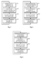
- fig. 4 illustrates schematically a method for compensating for cyclic variations in nip pressure.
- One possible source of cyclic variations is an eccentricity of the backing roll, which may occur in the backing roll as a whole or only at some part of it.
- Other possible sources of cyclic variations include, but are not limited to, resonant vibrations in the structures of the coating head, as well as machine direction oscillations in the thickness of the fibrous web that exist already when the fibrous web comes to the coating head.
- a coating machine may comprise a number (say, four) of coating heads, in which case any machine direction interference that occurred in one of the previous coating heads may be observed in the later coating heads as a machine direction oscillation in web thickness.
- the structures of the different coating heads may have essentially similar features, which means that machine direction interference may occur at essentially the same frequency in all of them, and even accumulate towards the end of the coating machine in a particularly awkward way. It should be noted that a scanning measurement of web thickness at a measurement frame has a certain sampling frequency, which in the worst case may fold together with a fast machine direction oscillation to produce measurement results in the form of an envelope curve that has little relevance to the actual thickness variations or coat weight variations of the web.
- Step 401 in fig. 4 represents detecting cyclic variations in nip pressure. This step requires that output signals from the sensor in the backing roll have been repeatedly read and converted into a form in which they can be processed with a signal processing algorithm (or, as an alternative, driven through a filter bank). Methods and signal processing arrangements for detecting cyclic variations in a signal are well known as such, and the selection of method and arrangement has no significance to the present invention.
- Step 402 represents calculating control values for the actuators that would implement a cyclic correction, i.e. a cyclic change in the created nip pressure that has the same frequency and amplitude as the detected cyclic variation but with a phase shift of pi radians. In fig.
- step 403 represents summing the control values obtained at step 402 with other contributions to obtain the control values.
- step 402 and step 403 belong to the wider concept of deriving a number of actuator control values.
- Step 404 represents delivering the calculated actuator control values as commands to the respective actuators that contribute to creating the nip pressure.
- Fig. 5 illustrates schematically a method for compensating for slower machine direction variations in the amount of coating.
- Step 501 represents measuring an amount of coating on the fibrous web downstream from the coating head in a direction of movement of the fibrous web. Such a measurement typically involves a certain degree of averaging, because e.g. in a scanning measurement the scanning time across the whole width of the web may be 20-30 seconds in a wide machine. It should be noted that a traditional scanning measurement at a measurement frame is not capable of properly differentiating between fast machine direction and cross direction phenomena. Therefore it is particularly advantageous in the present invention to additionally use a method according to the principle illustrated in fig. 4 to reduce the effect of fast machine direction variations, which could otherwise be confused with assumed cross direction phenomena at the scanning measurement.
- Step 502 in fig. 5 represents calculating what could be called the basic level of control values.
- the designation "basic level” means here that a basic distribution of nip pressure, which corresponds to an even coating of the desired optimal thickness and which changes at most slowly, should be created. In the ideal situation the basic level of control values calculated at step 502 would remain the same, and the measurement of step 501 would constantly show the amount of coating to be at the optimal value.
- step 503 represents summing the control values obtained at step 502 with other contributions to obtain the control values.
- Steps 502 and 503 thus belong to the wider concept of deriving a number of actuator control values, wherein a contribution indicative of the measured amount of coating is used in said deriving of the actuator control values.
- Step 504 represents delivering the calculated actuator control values as commands to the respective actuators that contribute to creating the nip pressure.
- Fig. 6 illustrates schematically a method for compensating for other phenomena, which originally may be not directly associated with coating layer thickness, coat weight or nip pressure at a coating head at all.
- barring which is a general definition of phenomena such as self excited vibration of the calender stack and regenerative wear of the calender rolls. Since barring is an oscillatory phenomenon by nature, it may be possible to balance and partially prevent it by deliberately introducing oscillatory excitation signals at a correct frequency and phase that counteract the original mechanisms that create barring.
- step 601 represents obtaining information indicative of barring oscillations in a calender that is located downstream from the coating head in a direction of movement of the fibrous web.
- step 602 represents calculating compensatory values that, when put into effect, will cause deliberate variations in nip pressure at the coating head. These in turn will cause deliberate variations in coating layer thickness or coat weight. As the fibrous web proceeds to the calender, said variations in coating layer thickness or coat weight will cause roll bearings in the calender to experience cyclically changing variations in the tension forces that are created in supporting the rolls.
- the deliberately created variations in coating layer thickness or coat weight must have a spatial frequency and phase that correspond to a frequency of said barring oscillations, the distance between the coating head and said calender in the direction of movement of the fibrous web, and a propagation rate of the fibrous web. If and when all these phenomena can be properly taken into account, the contributions to the actuator control values that are calculated at step 602 will effect compensating for the barring oscillations.
- the method of fig. 6 comprises the summing step 603 and the step of delivering the derived actuator control values as commands to the respective actuators that contribute to creating the nip pressure 604.
- actuators that contribute to creating the nip pressure at the coating head, apart from the natural assumption that they are available and capable of performing the required task.
- selection of actuators for the purposes of the present invention is not trivial.
- Traditionally used actuators comprise for example a linear screw and an electric motor that drives a nut around the linear screw.
- Such an actuator is accurate and powerful, but not particularly fast, at least not without sacrificing one or the other of the first-mentioned characteristics.
- hydraulic actuators have been used, where a proportional- or servo valve regulates the flow of hydraulic fluid to and from a working cylinder.
- it is difficult to build a hydraulic actuator so that it would simultaneously fulfil all three requirements of accuracy, power, and fast response, preferably combined with a reasonable price and robustness of operation in demanding industrial conditions.
- a digital hydraulic actuator is one which comprises a number of on/off type (i.e. digitally operated) hydraulic valves, and the displacement and/or output force of which depends on how many of said valves are open at one time.
- Fig. 7 illustrates the principle of a so-called hydraulic digital to analog converter, which has four on/off valves 701, 702, 703, and 704 coupled in parallel between an input 705 and an output 706.
- the flow rates in open state of the valves are Q, 2Q, 4Q, and 8Q from left to right, where Q is the flow rate of valve 701 in open state.
- the combined flow rate through a hydraulic digital to analog converter with n component valves with exponentially increasing flow rates has 2 n possible values, and it can be controlled with a digital word n bits long.
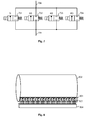
- Fig. 8 illustrates schematically a coating head, not covered by the claims, in which a number of actuators are configured to press a coating blade 801 is towards a backing roll 802.
- Actuator 803 is shown as an example.
- the actuators are located at regular intervals along the length of the coating blade 801.
- the fact that the actuators are digital hydraulic actuators is emphasized schematically in fig. 8 by showing four control lines from an actuator controller 804 to each actuator, as if each actuator comprised four hydraulic on/off valves in parallel like in fig. 7 , and as if each actuator was controlled with a four-bit word delivered along a parallel bus from the actuator controller.
- the number of distinct valves in each digital hydraulic actuator is not significant to the purposes of the present invention, so it may differ even very much from four. As with all applications of digital hydraulics, the number of valves is a compromise between cost and desired size of the quantization step in the phenomenon to be controlled.
- the combination of measuring the nip pressure with a sensor integrated in the backing roll and using digital hydraulic actuators is so advantageous and complete in implementing all desired fuctions of controlling the nip that it may allow deriving the actuator control values completely without any feedback from LVDT (Linear Variable Differential Transformer) sensors or any other detection of current position of individual actuators.
- Significant savings in both manufacturing cost and complicatedness of implementation may be achieved by leaving out the position sensors, which have been considered essential in prior art nip control arrangements. If position sensors are to be left out, it is preferable to manufacture the profiler bar of a material that has a high enough yield point, so that it is unlikely that a yield point of the material could be reached during normal operation of the actuators.
- the invention is applicable to both stiff blade and bent blade mode driving of the coating head. It is even possible to operate on the so-called grey zone between stiff and bent blade mode driving, because it is possible to deduce the direction of the response locally from the changes in the nip pressure, even if the response behaved differently at different locations in the cross direction of the machine.
- the invention is also applicable to controlling a nip pressure between rolls in a film transfer coating head, utilising sensors integrated in the rolls. If the actuators (typically: actuator cylinders, electromechanical actuators or digital hydraulic actuators) of such a film transfer coating head are fast enough, it is possible to utilise the principle explained above to compensate for vibrations that occur in such a film transfer coating head.
- a particular advantage of the invention is the possibility to base the fast and active control of nip pressure in a coating head on nip pressure measured from a rotating roll, which means that run-time control of the nip pressure profile is force based (as opposed to the location based control of most prior art systems).
- run-time control of the nip pressure profile is force based (as opposed to the location based control of most prior art systems).
- the force-based measurement gives superior results in obtained coating smoothness and dynamic controllability of the whole coating process.
Landscapes
- Engineering & Computer Science (AREA)
- Textile Engineering (AREA)
- Chemical & Material Sciences (AREA)
- Analytical Chemistry (AREA)
- Physics & Mathematics (AREA)
- General Physics & Mathematics (AREA)
- Mechanical Engineering (AREA)
- Application Of Or Painting With Fluid Materials (AREA)
- Coating Apparatus (AREA)
- Paper (AREA)
Claims (12)
- Procédé de commande d'une tête de couchage configurée pour exercer une pression de ligne de contact sur une bande fibreuse (102) à enduire tandis que la bande fibreuse est soutenue par un contre-rouleau (101), dans lequel le procédé comprend :- la lecture d'un signal émetteur d'un capteur (105) intégré dans le contre-rouleau, produisant (401) ainsi une indication mesurée de la pression de ligne de contact,- la dérivation (402) d'un nombre de valeurs de commande d'actionneur au moins partiellement de ladite indication mesurée de la pression de ligne de contact, et- la livraison (404) desdites valeurs de commande d'actionneur comme commandes à un nombre d'actionneurs respectifs (202) qui contribuent à créer la pression de ligne de contact, pour commander une quantité d'une substance de couchage sur la bande fibreuse dans la tête de couchage ;dans lequel la pression de ligne de contact est exercée en utilisant ledit nombre d'actionneurs (202) pour presser une lame de couchage (201) vers la bande fibreuse, caractérisé en ce que ledit nombre d'actionneurs (202) pressent ladite lame de couchage (201) indirectement en agissant sur une barre de profilage (203) qui presse ladite lame de couchage (201) vers la bande fibreuse (102).
- Procédé selon la revendication 1, dans lequel ledit nombre d'actionneurs (202) sont opérés de façon cyclique en phase avec une rotation du contre-rouleau (101) autour d'un axe de rotation longitudinal, afin de compenser une excentricité du contre-rouleau (101) par rapport au dit axe de rotation.
- Procédé selon l'une quelconque des revendications précédentes, dans lequel lesdites valeurs de commande d'actionneur sont des valeurs numériques, et lesdits actionneurs (202) sont des actionneurs hydrauliques numériques.
- Procédé selon l'une quelconque des revendications précédentes, dans lequel le procédé comprend :- en aval de la tête de couchage dans un sens de mouvement de la bande fibreuse (102), la mesure (501) d'une quantité de couchage sur la bande fibreuse (102), et- l'utilisation (502, 503) d'une contribution indicative de la quantité mesurée de couchage pour dériver ledit nombre de valeurs de commande d'actionneur.
- Procédé selon la revendication 4, dans lequel la quantité de couchage sur la bande fibreuse (102) est mesurée par une des mesures suivantes : une mesure de balayage de la masse sèche sur la bande fibreuse, une mesure de tension sur une surface d'un rouleau dans une bobine.
- Procédé selon l'une quelconque des revendications précédentes, dans lequel le procédé comprend :- l'obtention (601) d'informations indiquant des oscillations de rotation dans une calandre située en aval de la tête de couchage dans un sens de mouvement de la bande fibreuse (102), et- l'utilisation (602, 603) desdites informations pour dériver ledit nombre de valeurs de commande d'actionneur, compensant ainsi lesdites oscillations de rotation en créant de façon délibéré des variations dans l'épaisseur de la couche de couchage ou la masse du couchage à une fréquence spatiale et une phase qui correspondent à une fréquence desdites oscillations de rotation, la distance entre la tête de couchage et ladite calandre dans le sens de mouvement de la bande fibreuse (102), et une vitesse de propagation de la bande fibreuse (102).
- Procédé selon l'une quelconque des revendications précédentes, dans lequel l'étape de dérivation (402) dudit nombre de valeurs de commande d'actionneur est exécutée sans rétroaction d'une position courante détectée quelconque d'actionneurs individuels (202).
- Agencement pour la commande d'une tête de couchage configurée pour exercer une pression de ligne de contact sur une bande fibreuse (102) à enduire tandis que la bande fibreuse est soutenue par un contre-rouleau (101), dans lequel l'agencement comprend :- un capteur (105) intégré dans le contre-rouleau (101),- un nombre d'actionneurs (202) configurés pour contribuer à la création de la pression de ligne de contact en pressant une lame de couchage (201) vers la bande fibreuse (102),- un système de lecture (107) configuré pour lire un signal émetteur dudit capteur (105) et pour produire une indication mesurée de la pression de ligne de contact, et- une unité de commande (108) configurée pour dériver un nombre de valeurs de commande d'actionneur au moins partiellement de ladite indication mesurée de la pression de ligne de contact, et pour livrer lesdites valeurs de commande d'actionneur comme commandes au dit nombre d'actionneurs (202) pour commander une quantité d'une substance de couchage sur la bande fibreuse dans la tête de couchage ; caractérisé par- une barre de profilage (203) située entre lesdits actionneurs (202) et ladite lame de couchage (201).
- Agencement selon la revendication 8, dans lequel lesdits actionneurs (202) sont des actionneurs hydrauliques numériques.
- Agencement selon l'une quelconque des revendications 8 ou 9, dans lequel :- ladite unité de commande (108) est configurée pour recevoir d'un dispositif de mesure (109) une indication d'une quantité de couchage sur la bande fibreuse (102) en aval de la tête de couchage dans un sens de mouvement de la bande fibreuse (102), et- ladite unité de commande (108) est configurée pour utiliser une contribution indiquant la quantité mesurée de couchage pour dériver ledit nombre de valeurs de commande d'actionneur.
- Appareil selon l'une quelconque des revendications 8 à 10, dans lequel :- ladite unité de commande (108) est configurée pour obtenir des informations indiquant des oscillations de rotation dans une calandre située en aval de la tête de couchage dans un sens de mouvement de la bande fibreuse (102), et- ladite unité de commande (108) est configurée pour utiliser lesdites informations pour dériver ledit nombre de valeurs de commande d'actionneur, afin de compenser lesdites oscillations de rotation en créant de façon délibérée des variations dans l'épaisseur de la couche de couchage ou la masse du couchage à une fréquence spatiale et une phase qui correspondent à une fréquence desdites oscillations de rotation, la distance entre la tête de couchage et ladite calandre dans le sens de mouvement de la bande fibreuse (102), et une vitesse de propagation de la bande fibreuse (102).
- Tête de couchage pour enduire une bande fibreuse, caractérisée en ce que la tête de couchage comprend un agencement selon la revendication 8.
Applications Claiming Priority (1)
| Application Number | Priority Date | Filing Date | Title |
|---|---|---|---|
| PCT/FI2010/050422 WO2011148031A1 (fr) | 2010-05-25 | 2010-05-25 | Procédé et appareil pour la commande d'une tête de couchage, et tête de couchage |
Publications (2)
| Publication Number | Publication Date |
|---|---|
| EP2576082A1 EP2576082A1 (fr) | 2013-04-10 |
| EP2576082B1 true EP2576082B1 (fr) | 2014-07-16 |
Family
ID=43617031
Family Applications (1)
| Application Number | Title | Priority Date | Filing Date |
|---|---|---|---|
| EP10725224.9A Not-in-force EP2576082B1 (fr) | 2010-05-25 | 2010-05-25 | Procédé et appareil pour la commande d'une tête de couchage, et tête de couchage |
Country Status (4)
| Country | Link |
|---|---|
| US (1) | US9393593B2 (fr) |
| EP (1) | EP2576082B1 (fr) |
| CN (1) | CN102905798B (fr) |
| WO (1) | WO2011148031A1 (fr) |
Families Citing this family (13)
| Publication number | Priority date | Publication date | Assignee | Title |
|---|---|---|---|---|
| US9540769B2 (en) | 2013-03-11 | 2017-01-10 | International Paper Company | Method and apparatus for measuring and removing rotational variability from a nip pressure profile of a covered roll of a nip press |
| SE538854C2 (sv) | 2014-01-09 | 2017-01-03 | Valmet Oy | Rullstol för mottagande och upprullning av en pappersbana, som kommer från en torkcylinder i en pappersmaskin, till en rulle, samt en pappersmaskin som använder en rullstol |
| EP3379222B1 (fr) | 2017-03-22 | 2020-12-30 | Methode Electronics Malta Ltd. | Ensemble de capteur à base magnétoélastique |
| US11491832B2 (en) | 2018-02-27 | 2022-11-08 | Methode Electronics, Inc. | Towing systems and methods using magnetic field sensing |
| US11014417B2 (en) | 2018-02-27 | 2021-05-25 | Methode Electronics, Inc. | Towing systems and methods using magnetic field sensing |
| US11084342B2 (en) | 2018-02-27 | 2021-08-10 | Methode Electronics, Inc. | Towing systems and methods using magnetic field sensing |
| US11135882B2 (en) | 2018-02-27 | 2021-10-05 | Methode Electronics, Inc. | Towing systems and methods using magnetic field sensing |
| US11221262B2 (en) | 2018-02-27 | 2022-01-11 | Methode Electronics, Inc. | Towing systems and methods using magnetic field sensing |
| US10670479B2 (en) | 2018-02-27 | 2020-06-02 | Methode Electronics, Inc. | Towing systems and methods using magnetic field sensing |
| DE102019117901A1 (de) * | 2019-07-03 | 2021-01-07 | Voith Patent Gmbh | Schabvorrichtung und Verfahren zur Ermittlung des Anpressdrucks eines Schabers |
| TWI695917B (zh) * | 2020-01-15 | 2020-06-11 | 正承精密工業股份有限公司 | 用於含浸機的膠料刮除裝置 |
| CN114720324B (zh) * | 2022-06-01 | 2022-09-06 | 浙江双元科技股份有限公司 | 一种锂电池极片净涂层量检测方法、装置及系统 |
| CN116289316A (zh) * | 2023-03-31 | 2023-06-23 | 河南逸祥卫生科技有限公司 | 一种可精准控制乳霜涂布量乳霜纸制造工艺 |
Family Cites Families (13)
| Publication number | Priority date | Publication date | Assignee | Title |
|---|---|---|---|---|
| JPH0515833A (ja) | 1991-07-15 | 1993-01-26 | Mitsubishi Paper Mills Ltd | ブレード型塗工装置及びその塗工量制御方法 |
| US5597415A (en) * | 1995-02-09 | 1997-01-28 | Voith Sulzer Paper Technology North America, Inc. | Profiling bar for a web coating device |
| DE19627456A1 (de) | 1996-07-08 | 1998-01-15 | Voith Sulzer Papiermasch Gmbh | Auftragwerk zum direkten Auftragen eines flüssigen oder pastösen Mediums auf eine laufende Materialbahn, insbesondere aus Papier oder Karton |
| JP4416213B2 (ja) * | 1998-08-06 | 2010-02-17 | フォイト ズルツァー パピーアテヒニク パテント ゲゼルシャフト ミット ベシュレンクテル ハフツング | 回転中のロールの不都合な振動を能動的に弱めるための装置及び方法 |
| US7185537B2 (en) | 2003-06-04 | 2007-03-06 | Metso Paper, Inc. | Nip and loading analysis system |
| DE102004040622A1 (de) * | 2004-08-21 | 2006-02-23 | Voith Paper Patent Gmbh | Rakelvorrichtung |
| FI20055020L (fi) | 2005-01-17 | 2006-07-18 | Metso Paper Inc | Paineprofiilin ON-linemittaus |
| FI20055019L (fi) | 2005-01-17 | 2006-07-18 | Metso Paper Inc | Rainan kireysprofiilin mittausmenetelmä ja sitä soveltava tela |
| JP4215739B2 (ja) | 2005-04-11 | 2009-01-28 | 三菱製紙株式会社 | 塗布量プロファイル制御方法 |
| FI20065189L (fi) | 2006-03-23 | 2007-09-24 | Metso Paper Inc | Voimien mittaus pyörivästä telasta |
| JP4879070B2 (ja) * | 2007-03-30 | 2012-02-15 | 富士フイルム株式会社 | 塗布装置、及び塗布方法 |
| WO2009092761A2 (fr) | 2008-01-24 | 2009-07-30 | Metso Paper, Inc. | Poste de revêtement de fabrication de papier avec rouleau de film sensible à la pression |
| EP2250111A2 (fr) | 2008-02-12 | 2010-11-17 | UPM-Kymmene Oyj | Procédé et dispositif pour mesurer la pression dans la pince et/ou le profil de pression dans la pince d'une unité d'impression d'une presse à imprimer |
-
2010
- 2010-05-25 CN CN201080066929.4A patent/CN102905798B/zh not_active Expired - Fee Related
- 2010-05-25 US US13/699,703 patent/US9393593B2/en not_active Expired - Fee Related
- 2010-05-25 WO PCT/FI2010/050422 patent/WO2011148031A1/fr not_active Ceased
- 2010-05-25 EP EP10725224.9A patent/EP2576082B1/fr not_active Not-in-force
Also Published As
| Publication number | Publication date |
|---|---|
| CN102905798B (zh) | 2015-05-27 |
| US9393593B2 (en) | 2016-07-19 |
| WO2011148031A1 (fr) | 2011-12-01 |
| EP2576082A1 (fr) | 2013-04-10 |
| CN102905798A (zh) | 2013-01-30 |
| US20130064968A1 (en) | 2013-03-14 |
Similar Documents
| Publication | Publication Date | Title |
|---|---|---|
| EP2576082B1 (fr) | Procédé et appareil pour la commande d'une tête de couchage, et tête de couchage | |
| CN101542042B (zh) | 用于控制纤维幅材的制造或整饰工艺的方法及系统 | |
| US8613972B2 (en) | Papermaking coating station with pressure-sensitive film roll | |
| WO2001030533A1 (fr) | Systeme servant a controler une surface dynamique | |
| US9079739B2 (en) | Apparatus for controlling the nip force/pressure between two rotating cylinders | |
| US7255000B2 (en) | Method and an arrangement for controlling position and/or force of an elongated rolling device | |
| ES2533432T3 (es) | Unidad de gofrado y procedimiento de gofrado | |
| US5409732A (en) | Roll gap controller for regulating coating thickness | |
| US20010000065A1 (en) | Method and apparatus for damping contact oscillations of rotating rolls | |
| JPS63295788A (ja) | 材料ウエブへの圧力負荷の分布の制御方法、材料ウエブの処理装置および圧力処理ニップの調整方法 | |
| US9073282B2 (en) | Process for controlling the nip force/pressure between two rotating cylinders | |
| JPS5822599B2 (ja) | 可動シ−ト材料の処理方法及びそのための処理機 | |
| US8790495B2 (en) | Web production with increased process efficiency | |
| US6299571B1 (en) | System and method for controlling deflection of a dynamic surface | |
| EP2576202B1 (fr) | Procédé de réglage automatique de l'intervalle rouleau presseur/rouleau applicateur de colle sur une encolleuse | |
| US7235157B2 (en) | Method for controlling one or more surface quality variables of a fiber web in a shoe calender | |
| CN101688366A (zh) | 用于补偿周期性力矩波动的装置和方法 | |
| JP6751447B2 (ja) | 真空内のフレキシブル基板の連続処理のための装置、及びそのための方法 | |
| US20060100823A1 (en) | System and method for estimating production and feed consistency disturbances | |
| WO2007107625A1 (fr) | Mesure de force sur un rouleau tournant | |
| CA2260508A1 (fr) | Methode pour utiliser un systeme de cylindre de calandre, et systeme de cylindre de calandre | |
| JP4852424B2 (ja) | マルチニップカレンダ又はカレンダ・アレイにおける振動を防止する方法及び配置 | |
| JP2026020052A (ja) | カレンダーを運転する方法 | |
| JP2000248487A (ja) | 誘導加熱方式によるカレンダーロール加熱装置 | |
| CN117940270A (zh) | 具有支承元件的超声加工装置 |
Legal Events
| Date | Code | Title | Description |
|---|---|---|---|
| PUAI | Public reference made under article 153(3) epc to a published international application that has entered the european phase |
Free format text: ORIGINAL CODE: 0009012 |
|
| 17P | Request for examination filed |
Effective date: 20121011 |
|
| AK | Designated contracting states |
Kind code of ref document: A1 Designated state(s): AL AT BE BG CH CY CZ DE DK EE ES FI FR GB GR HR HU IE IS IT LI LT LU LV MC MK MT NL NO PL PT RO SE SI SK SM TR |
|
| DAX | Request for extension of the european patent (deleted) | ||
| GRAP | Despatch of communication of intention to grant a patent |
Free format text: ORIGINAL CODE: EPIDOSNIGR1 |
|
| INTG | Intention to grant announced |
Effective date: 20131014 |
|
| GRAS | Grant fee paid |
Free format text: ORIGINAL CODE: EPIDOSNIGR3 |
|
| GRAP | Despatch of communication of intention to grant a patent |
Free format text: ORIGINAL CODE: EPIDOSNIGR1 |
|
| RAP1 | Party data changed (applicant data changed or rights of an application transferred) |
Owner name: VALMET TECHNOLOGIES, INC. |
|
| INTG | Intention to grant announced |
Effective date: 20140320 |
|
| GRAA | (expected) grant |
Free format text: ORIGINAL CODE: 0009210 |
|
| AK | Designated contracting states |
Kind code of ref document: B1 Designated state(s): AL AT BE BG CH CY CZ DE DK EE ES FI FR GB GR HR HU IE IS IT LI LT LU LV MC MK MT NL NO PL PT RO SE SI SK SM TR |
|
| REG | Reference to a national code |
Ref country code: GB Ref legal event code: FG4D |
|
| REG | Reference to a national code |
Ref country code: CH Ref legal event code: EP |
|
| REG | Reference to a national code |
Ref country code: IE Ref legal event code: FG4D |
|
| REG | Reference to a national code |
Ref country code: AT Ref legal event code: REF Ref document number: 677255 Country of ref document: AT Kind code of ref document: T Effective date: 20140815 |
|
| REG | Reference to a national code |
Ref country code: DE Ref legal event code: R096 Ref document number: 602010017508 Country of ref document: DE Effective date: 20140828 |
|
| REG | Reference to a national code |
Ref country code: NL Ref legal event code: VDEP Effective date: 20140716 |
|
| REG | Reference to a national code |
Ref country code: LT Ref legal event code: MG4D |
|
| PG25 | Lapsed in a contracting state [announced via postgrant information from national office to epo] |
Ref country code: NO Free format text: LAPSE BECAUSE OF FAILURE TO SUBMIT A TRANSLATION OF THE DESCRIPTION OR TO PAY THE FEE WITHIN THE PRESCRIBED TIME-LIMIT Effective date: 20141016 Ref country code: GR Free format text: LAPSE BECAUSE OF FAILURE TO SUBMIT A TRANSLATION OF THE DESCRIPTION OR TO PAY THE FEE WITHIN THE PRESCRIBED TIME-LIMIT Effective date: 20141017 Ref country code: LT Free format text: LAPSE BECAUSE OF FAILURE TO SUBMIT A TRANSLATION OF THE DESCRIPTION OR TO PAY THE FEE WITHIN THE PRESCRIBED TIME-LIMIT Effective date: 20140716 Ref country code: PT Free format text: LAPSE BECAUSE OF FAILURE TO SUBMIT A TRANSLATION OF THE DESCRIPTION OR TO PAY THE FEE WITHIN THE PRESCRIBED TIME-LIMIT Effective date: 20141117 Ref country code: ES Free format text: LAPSE BECAUSE OF FAILURE TO SUBMIT A TRANSLATION OF THE DESCRIPTION OR TO PAY THE FEE WITHIN THE PRESCRIBED TIME-LIMIT Effective date: 20140716 Ref country code: SE Free format text: LAPSE BECAUSE OF FAILURE TO SUBMIT A TRANSLATION OF THE DESCRIPTION OR TO PAY THE FEE WITHIN THE PRESCRIBED TIME-LIMIT Effective date: 20140716 Ref country code: BG Free format text: LAPSE BECAUSE OF FAILURE TO SUBMIT A TRANSLATION OF THE DESCRIPTION OR TO PAY THE FEE WITHIN THE PRESCRIBED TIME-LIMIT Effective date: 20141016 |
|
| PG25 | Lapsed in a contracting state [announced via postgrant information from national office to epo] |
Ref country code: LV Free format text: LAPSE BECAUSE OF FAILURE TO SUBMIT A TRANSLATION OF THE DESCRIPTION OR TO PAY THE FEE WITHIN THE PRESCRIBED TIME-LIMIT Effective date: 20140716 Ref country code: PL Free format text: LAPSE BECAUSE OF FAILURE TO SUBMIT A TRANSLATION OF THE DESCRIPTION OR TO PAY THE FEE WITHIN THE PRESCRIBED TIME-LIMIT Effective date: 20140716 Ref country code: CY Free format text: LAPSE BECAUSE OF FAILURE TO SUBMIT A TRANSLATION OF THE DESCRIPTION OR TO PAY THE FEE WITHIN THE PRESCRIBED TIME-LIMIT Effective date: 20140716 Ref country code: IS Free format text: LAPSE BECAUSE OF FAILURE TO SUBMIT A TRANSLATION OF THE DESCRIPTION OR TO PAY THE FEE WITHIN THE PRESCRIBED TIME-LIMIT Effective date: 20141116 Ref country code: NL Free format text: LAPSE BECAUSE OF FAILURE TO SUBMIT A TRANSLATION OF THE DESCRIPTION OR TO PAY THE FEE WITHIN THE PRESCRIBED TIME-LIMIT Effective date: 20140716 |
|
| REG | Reference to a national code |
Ref country code: DE Ref legal event code: R097 Ref document number: 602010017508 Country of ref document: DE |
|
| PG25 | Lapsed in a contracting state [announced via postgrant information from national office to epo] |
Ref country code: DK Free format text: LAPSE BECAUSE OF FAILURE TO SUBMIT A TRANSLATION OF THE DESCRIPTION OR TO PAY THE FEE WITHIN THE PRESCRIBED TIME-LIMIT Effective date: 20140716 Ref country code: EE Free format text: LAPSE BECAUSE OF FAILURE TO SUBMIT A TRANSLATION OF THE DESCRIPTION OR TO PAY THE FEE WITHIN THE PRESCRIBED TIME-LIMIT Effective date: 20140716 Ref country code: CZ Free format text: LAPSE BECAUSE OF FAILURE TO SUBMIT A TRANSLATION OF THE DESCRIPTION OR TO PAY THE FEE WITHIN THE PRESCRIBED TIME-LIMIT Effective date: 20140716 Ref country code: RO Free format text: LAPSE BECAUSE OF FAILURE TO SUBMIT A TRANSLATION OF THE DESCRIPTION OR TO PAY THE FEE WITHIN THE PRESCRIBED TIME-LIMIT Effective date: 20140716 Ref country code: IT Free format text: LAPSE BECAUSE OF FAILURE TO SUBMIT A TRANSLATION OF THE DESCRIPTION OR TO PAY THE FEE WITHIN THE PRESCRIBED TIME-LIMIT Effective date: 20140716 Ref country code: SK Free format text: LAPSE BECAUSE OF FAILURE TO SUBMIT A TRANSLATION OF THE DESCRIPTION OR TO PAY THE FEE WITHIN THE PRESCRIBED TIME-LIMIT Effective date: 20140716 |
|
| PLBE | No opposition filed within time limit |
Free format text: ORIGINAL CODE: 0009261 |
|
| STAA | Information on the status of an ep patent application or granted ep patent |
Free format text: STATUS: NO OPPOSITION FILED WITHIN TIME LIMIT |
|
| 26N | No opposition filed |
Effective date: 20150417 |
|
| PG25 | Lapsed in a contracting state [announced via postgrant information from national office to epo] |
Ref country code: SI Free format text: LAPSE BECAUSE OF FAILURE TO SUBMIT A TRANSLATION OF THE DESCRIPTION OR TO PAY THE FEE WITHIN THE PRESCRIBED TIME-LIMIT Effective date: 20140716 |
|
| REG | Reference to a national code |
Ref country code: CH Ref legal event code: PL |
|
| GBPC | Gb: european patent ceased through non-payment of renewal fee |
Effective date: 20150525 |
|
| PG25 | Lapsed in a contracting state [announced via postgrant information from national office to epo] |
Ref country code: CH Free format text: LAPSE BECAUSE OF NON-PAYMENT OF DUE FEES Effective date: 20150531 Ref country code: LU Free format text: LAPSE BECAUSE OF FAILURE TO SUBMIT A TRANSLATION OF THE DESCRIPTION OR TO PAY THE FEE WITHIN THE PRESCRIBED TIME-LIMIT Effective date: 20150525 Ref country code: LI Free format text: LAPSE BECAUSE OF NON-PAYMENT OF DUE FEES Effective date: 20150531 Ref country code: MC Free format text: LAPSE BECAUSE OF FAILURE TO SUBMIT A TRANSLATION OF THE DESCRIPTION OR TO PAY THE FEE WITHIN THE PRESCRIBED TIME-LIMIT Effective date: 20140716 |
|
| REG | Reference to a national code |
Ref country code: IE Ref legal event code: MM4A |
|
| REG | Reference to a national code |
Ref country code: FR Ref legal event code: ST Effective date: 20160129 |
|
| PG25 | Lapsed in a contracting state [announced via postgrant information from national office to epo] |
Ref country code: GB Free format text: LAPSE BECAUSE OF NON-PAYMENT OF DUE FEES Effective date: 20150525 Ref country code: IE Free format text: LAPSE BECAUSE OF NON-PAYMENT OF DUE FEES Effective date: 20150525 |
|
| PG25 | Lapsed in a contracting state [announced via postgrant information from national office to epo] |
Ref country code: FR Free format text: LAPSE BECAUSE OF NON-PAYMENT OF DUE FEES Effective date: 20150601 |
|
| PG25 | Lapsed in a contracting state [announced via postgrant information from national office to epo] |
Ref country code: BE Free format text: LAPSE BECAUSE OF FAILURE TO SUBMIT A TRANSLATION OF THE DESCRIPTION OR TO PAY THE FEE WITHIN THE PRESCRIBED TIME-LIMIT Effective date: 20140716 |
|
| PG25 | Lapsed in a contracting state [announced via postgrant information from national office to epo] |
Ref country code: MT Free format text: LAPSE BECAUSE OF FAILURE TO SUBMIT A TRANSLATION OF THE DESCRIPTION OR TO PAY THE FEE WITHIN THE PRESCRIBED TIME-LIMIT Effective date: 20140716 |
|
| PG25 | Lapsed in a contracting state [announced via postgrant information from national office to epo] |
Ref country code: HU Free format text: LAPSE BECAUSE OF FAILURE TO SUBMIT A TRANSLATION OF THE DESCRIPTION OR TO PAY THE FEE WITHIN THE PRESCRIBED TIME-LIMIT; INVALID AB INITIO Effective date: 20100525 Ref country code: SM Free format text: LAPSE BECAUSE OF FAILURE TO SUBMIT A TRANSLATION OF THE DESCRIPTION OR TO PAY THE FEE WITHIN THE PRESCRIBED TIME-LIMIT Effective date: 20140716 |
|
| PG25 | Lapsed in a contracting state [announced via postgrant information from national office to epo] |
Ref country code: HR Free format text: LAPSE BECAUSE OF FAILURE TO SUBMIT A TRANSLATION OF THE DESCRIPTION OR TO PAY THE FEE WITHIN THE PRESCRIBED TIME-LIMIT Effective date: 20140716 |
|
| PG25 | Lapsed in a contracting state [announced via postgrant information from national office to epo] |
Ref country code: TR Free format text: LAPSE BECAUSE OF FAILURE TO SUBMIT A TRANSLATION OF THE DESCRIPTION OR TO PAY THE FEE WITHIN THE PRESCRIBED TIME-LIMIT Effective date: 20140716 |
|
| PGFP | Annual fee paid to national office [announced via postgrant information from national office to epo] |
Ref country code: AT Payment date: 20170522 Year of fee payment: 8 Ref country code: FI Payment date: 20170511 Year of fee payment: 8 |
|
| PG25 | Lapsed in a contracting state [announced via postgrant information from national office to epo] |
Ref country code: MK Free format text: LAPSE BECAUSE OF FAILURE TO SUBMIT A TRANSLATION OF THE DESCRIPTION OR TO PAY THE FEE WITHIN THE PRESCRIBED TIME-LIMIT Effective date: 20140716 |
|
| PG25 | Lapsed in a contracting state [announced via postgrant information from national office to epo] |
Ref country code: AL Free format text: LAPSE BECAUSE OF FAILURE TO SUBMIT A TRANSLATION OF THE DESCRIPTION OR TO PAY THE FEE WITHIN THE PRESCRIBED TIME-LIMIT Effective date: 20140716 |
|
| REG | Reference to a national code |
Ref country code: AT Ref legal event code: MM01 Ref document number: 677255 Country of ref document: AT Kind code of ref document: T Effective date: 20180525 |
|
| PG25 | Lapsed in a contracting state [announced via postgrant information from national office to epo] |
Ref country code: AT Free format text: LAPSE BECAUSE OF NON-PAYMENT OF DUE FEES Effective date: 20180525 Ref country code: FI Free format text: LAPSE BECAUSE OF NON-PAYMENT OF DUE FEES Effective date: 20180525 |
|
| PGFP | Annual fee paid to national office [announced via postgrant information from national office to epo] |
Ref country code: DE Payment date: 20230519 Year of fee payment: 14 |
|
| REG | Reference to a national code |
Ref country code: DE Ref legal event code: R119 Ref document number: 602010017508 Country of ref document: DE |
|
| PG25 | Lapsed in a contracting state [announced via postgrant information from national office to epo] |
Ref country code: DE Free format text: LAPSE BECAUSE OF NON-PAYMENT OF DUE FEES Effective date: 20241203 |